EP1614948B1 - Soupape - Google Patents
Soupape Download PDFInfo
- Publication number
- EP1614948B1 EP1614948B1 EP05014519A EP05014519A EP1614948B1 EP 1614948 B1 EP1614948 B1 EP 1614948B1 EP 05014519 A EP05014519 A EP 05014519A EP 05014519 A EP05014519 A EP 05014519A EP 1614948 B1 EP1614948 B1 EP 1614948B1
- Authority
- EP
- European Patent Office
- Prior art keywords
- valve
- valve according
- arch
- valve body
- section
- Prior art date
- Legal status (The legal status is an assumption and is not a legal conclusion. Google has not performed a legal analysis and makes no representation as to the accuracy of the status listed.)
- Expired - Lifetime
Links
Images



Classifications
-
- F—MECHANICAL ENGINEERING; LIGHTING; HEATING; WEAPONS; BLASTING
- F16—ENGINEERING ELEMENTS AND UNITS; GENERAL MEASURES FOR PRODUCING AND MAINTAINING EFFECTIVE FUNCTIONING OF MACHINES OR INSTALLATIONS; THERMAL INSULATION IN GENERAL
- F16K—VALVES; TAPS; COCKS; ACTUATING-FLOATS; DEVICES FOR VENTING OR AERATING
- F16K1/00—Lift valves or globe valves, i.e. cut-off apparatus with closure members having at least a component of their opening and closing motion perpendicular to the closing faces
- F16K1/32—Details
- F16K1/34—Cutting-off parts, e.g. valve members, seats
- F16K1/36—Valve members
- F16K1/40—Valve members of helical shape
-
- F—MECHANICAL ENGINEERING; LIGHTING; HEATING; WEAPONS; BLASTING
- F16—ENGINEERING ELEMENTS AND UNITS; GENERAL MEASURES FOR PRODUCING AND MAINTAINING EFFECTIVE FUNCTIONING OF MACHINES OR INSTALLATIONS; THERMAL INSULATION IN GENERAL
- F16K—VALVES; TAPS; COCKS; ACTUATING-FLOATS; DEVICES FOR VENTING OR AERATING
- F16K47/00—Means in valves for absorbing fluid energy
- F16K47/08—Means in valves for absorbing fluid energy for decreasing pressure or noise level and having a throttling member separate from the closure member, e.g. screens, slots, labyrinths
- F16K47/12—Means in valves for absorbing fluid energy for decreasing pressure or noise level and having a throttling member separate from the closure member, e.g. screens, slots, labyrinths the throttling channel being of helical form
Definitions
- the invention relates to a valve which is movable from an open position to a closed position and back, with a valve body whose base is adapted to the inner contour of a conduit and having a spirally formed vault.
- a valve of the type mentioned is, for example, from GB 15 970 A AO 1914 known.
- the conical vault can be brought from an open to a closed position by means of a release rod, which can be actuated from the outside.
- a similar valve is in the DE 500 753 C shown here, inter alia, with a spherical segment-like vault of the base body.
- a rod-like triggering element is provided, which, similar to the GB 15 970 A , AO 1914, is operable from the outside.
- the cross section of the spiral strand of the valve body is selected so that superimposed passages of the spiral strand engage in the closed position.
- the valve according to the invention operates effectively in that its cross-section is opened or closed uniformly. Due to the spiral-like cut the passage opening is maximum, so that there is a low flow resistance. Due to the supporting effect of the spiral superimposed segments, large diameters of lines can be bridged. This working principle is comparable to a vaulted cellar.
- the starting behavior of the valve can be adjusted via the cone angle or the pitch of the spiral.
- the design of the profile of the spiral strand of the valve body, the flow resistance and thus the performance of the valve can be adjusted. By selecting the profile, the supporting effect of the superimposed passages of the spiral strand can be improved.
- cross section of the spiral strand means the cutting plane perpendicular to the axis of the rolled spiral strand, as illustrated in connection with FIG.
- the vault may be a conical vault, but it is also advantageous if the vault is a spherical segment-like vault.
- a trigger element is provided, which is preferably attached to the zenith of the vault. This trigger element is intended to bring the valve in the open position.
- the trigger element can be actuated by a spring attached to it. With a separate spring on the trigger element, the valve can be used as a gas flow monitor.
- the spring is arranged in the axis of symmetry of the concavity of the arch.
- valve body itself serves as a spring which controls the triggering directly.
- valve according to the invention In order to use the valve according to the invention as a guard, in particular gas monitor, it must be the appropriate operating conditions, such as pressure, flow rate, etc., adapted.
- the spirally formed vault is made of metal or plastic, for example polypropylene, polyethylene, polyamide or the like. It is possible to add to the plastic fillers, such as glass fiber, carbon black or the like, so that the desired spring properties of the valve body are obtained.
- the cross section of the spiral strand is constant over at least part of its length. But it may also be required that the valve over its axial length has an approximately uniform bending stiffness. In this case it can be provided that the cross section of the spiral strand decreases from the base to the zenith of the arch. The thickness of the spiral strand therefore becomes smaller as the circumference of the valve body decreases.
- the flow-through opening formed in the spiral-shaped vault in the open position remains partially closed in the open position or can be closed. This can be achieved, for example, by already cutting only a portion of the valve body during manufacture in a spiral manner. But it can also be provided to subsequently apply a cover.
- Such a cover may rest more or less closely on the valve body and thus provide an increase in the back pressure.
- the flow resistance can be adjusted, which has an effect on the closing properties of the valve.
- a manufacturing simplification results when the cover is formed asymmetrically with respect to the longitudinal axis of the valve body.
- the cover element possible manufacturing tolerances can be compensated or operating ranges are fine-tuned.
- the asymmetric cover is welded to the valve body.
- the cover can also be used as a closure body.
- FIG. 1 shows an embodiment of a valve according to the present invention, in the open state, in which a valve body 10, which consists of a spirally cut vault 12 with integrally mounted base 14 in the open state.
- the vault 12 is conical in the embodiment shown here, but it is also a hemispherical configuration or a spherical portion-like configuration, a pyramid-like design and the like conceivable.
- the light-off behavior of the valve is adjustable.
- the inventive Valve even if it is used as a gas flow monitor, can be optimized for special applications. Other settings are explained below.
- Figure 2 shows the valve of Figure 1 in a perspective view, it being understood that the cross section of the arch 12 can be uniformly opened or closed. This minimizes the actuation force for the valve.
- FIG. 3 shows the valve in the closed state.
- the superimposed passages of the spiral strand 24 of the arch 12 in the form of a cone cause them to be supported against each other, similar to a type of vaulted cellar.
- FIG. 4 shows how in the closed state of the valve, the spiral of the vault 12 is closed in itself and provides the base 14 for the blocking of the pipe diameter.
- FIG 5 the valve according to the invention in its conical configuration in the installed state in a tube 20 is shown.
- a trigger element 18 on which, for example, an actuator engages.
- the valve can be used as a gas flow monitor. It must be ensured that, as shown in Figure 6, the trigger element 18 engages a force F in the direction indicated by the arrow. It is irrelevant whether this force F is caused by a mounted above the trigger element 18 spring or by a disposed within the cone or vault spring. It is only important that the spirally cut vault 12 is pulled apart so that the spiral passage opening 22 is expanded as evenly as possible.
- the valve body itself can be manufactured in fengnagna and acts depending on the material and design as a spring. An additional spring is thus superfluous in such an embodiment.
- FIG. 7 shows, in the partial image (a), schematically three superimposed passages of the spiral strand 24 of a valve, wherein in this embodiment the cross-sectional area 26 of the spiral strand 24 is rectangular and constant over the axial length of the valve body.
- the cross-sectional area 26 of the spiral strand 24 is rectangular and constant over the axial length of the valve body.
- a further embodiment shows the partial image (c) with a spiral strand 24, a cross section 26 "which is designed in the form of an inverted" V ".
- FIG. 8 shows in the partial image (a) an embodiment of the valve in which, starting at the base 14, the spiral strand 24 has a constant cross section up to the zenith 28, which is illustrated in this illustration by an equally constant thickness d of the spiral strand 24.
- the valve or, more precisely, the valve body 10 should have an approximately constant flexural rigidity over its axial length, this can be achieved by having the spiral strand 24 on the base 14 having a greater thickness d1 than shown in part (b) in the vicinity of the zenith 28, wherein the thickness d1 in the embodiment shown here decreases continuously to the thickness d2.
- the small thickness thus compensates for the smaller circumference of the valve body 10 and thus the lower effective area.
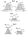
- Figure 9 shows an embodiment of a valve in which the valve body 10 is only partially, namely in the vicinity of the base 14, formed spirally. Manufacturing this can be done by, for example, from the vault 12 only a few courses of the spiral strand 24 are cut out. The upper portion of the arch 12 remains closed. The spiral strand 24 may be formed in other portions of the arch 12, so that it for example It would also be conceivable to keep the vault 12 closed in the vicinity of the base 4, while the spiral strand 24 is cut below the zenith 28.
- FIG. 10 shows an embodiment of a valve in which the cover element 30 is placed on the upper area of the valve body 10. It remains, as can be seen better in the partial image (b), a flow gap 32 between cover 30 and valve body 10th
- the cover element 34 shown in Figure 11 is asymmetrical, here in that the pointing to the base 14 edge 36 of the cover member is not parallel to the base 14, but at a preselectable angle. This also corresponds to an asymmetry with respect to the longitudinal axis of the valve body which is perpendicular to the base 14.
- the spiral flow opening 22, which defines a pitch angle can be achieved here by a different angular position of the cover 34, so that the flow-through 22 is more or less closed in partial areas.
- manufacturing tolerances can be compensated. After the optimal position of the cover 34 is found, this is firmly connected to the valve body, for example by gluing or welding with mechanical locking.
- FIG. 12 shows a valve with a cover element 38, into which a seal is introduced, here in the form of a sealing ring 40, which faces the base 14 of the valve.
- the detail view “X” shows how the sealing ring 40 is attached to the cover 38.
Landscapes
- Engineering & Computer Science (AREA)
- General Engineering & Computer Science (AREA)
- Mechanical Engineering (AREA)
- Check Valves (AREA)
- Magnetically Actuated Valves (AREA)
- Electrically Driven Valve-Operating Means (AREA)
- Temperature-Responsive Valves (AREA)
- Valve Housings (AREA)
- Lift Valve (AREA)
Claims (15)
- Soupape pouvant être amenée depuis une position ouverte vers une position fermée et inversement, comprenant un corps de soupape (10) dont la base (14) est adaptée au contour intérieur d'une conduite et qui présente une voûte réalisée en forme de spirale, caractérisée en ce que la section (26', 26") du brin spiralé (24) du corps de la soupape (10) est choisie de telle sorte que les passages superposés du brin spiralé (24) s'engagent les uns dans les autres dans la position fermée de la soupape.
- Soupape selon la revendication 1, caractérisée en ce que la voûte (12) est une voûte de type conique.
- Soupape selon la revendication 1, caractérisée en ce que la voûte (12) est une voûte en forme de segment sphérique.
- Soupape selon l'une des revendications 1 à 3, caractérisée en ce qu'un élément de déclenchement (18) qui amène la soupape dans la position ouverte ou la position fermée est fixé sur le sommet de la voûte (12)
- Soupape selon la revendication 4, caractérisée en ce que l'élément de déclenchement (18) peut être actionné au moyen d'un ressort installé sur lui.
- Soupape selon la revendication 4, caractérisée en ce que le corps de la soupape constitue le ressort.
- Soupape selon la revendication 5, caractérisée en ce que le ressort est agencé dans l'axe de symétrie de la concavité de la voûte (12).
- Soupape selon l'une des revendications 1 à 7, caractérisée en ce que la voûte réalisée en forme de spirale (12) est fabriquée en métal ou en matériau plastique, par exemple un polypropylène, un polyéthylène, un polyamide ou un matériau similaire.
- Soupape selon la revendication 8, caractérisée en ce que le matériau plastique contient une charge telle que des fibres de verre, de la suie ou des matières similaires.
- Soupape selon la revendication 1, caractérisée en ce que la section (26, 26', 26") du brin spiralé (24) est constante sur au moins une partie de sa longueur.
- Soupape selon la revendication 1, caractérisée en ce que la section du brin spiralé (24) diminue depuis la base (14) vers le sommet (28) de la voûte (12).
- Soupape selon la revendication 1, caractérisée en ce que l'ouverture de circulation (22) présente dans la position ouverte dans la voûte réalisée en forme de spirale (1) reste partiellement fermée ou peut être fermée dans la position ouverte de la soupape.
- Soupape selon l'une des revendications précédentes, caractérisée en ce qu'au moins une partie de la voûte réalisée en forme de spirale (12) est munie d'un élément de couverture (30, 34, 38).
- Soupape selon la revendication 13, caractérisée en ce que l'élément de couverture (34) est réalisé de façon asymétrique par rapport à l'axe longitudinal du corps de la soupape (10).
- Soupape selon la revendication 13, caractérisée en ce qu'un joint d'étanchéité (40) est installé dans l'élément de couverture (38).
Applications Claiming Priority (1)
| Application Number | Priority Date | Filing Date | Title |
|---|---|---|---|
| DE102004032584 | 2004-07-05 |
Publications (3)
| Publication Number | Publication Date |
|---|---|
| EP1614948A2 EP1614948A2 (fr) | 2006-01-11 |
| EP1614948A3 EP1614948A3 (fr) | 2006-02-01 |
| EP1614948B1 true EP1614948B1 (fr) | 2007-08-29 |
Family
ID=35045212
Family Applications (1)
| Application Number | Title | Priority Date | Filing Date |
|---|---|---|---|
| EP05014519A Expired - Lifetime EP1614948B1 (fr) | 2004-07-05 | 2005-07-05 | Soupape |
Country Status (4)
| Country | Link |
|---|---|
| EP (1) | EP1614948B1 (fr) |
| AT (1) | ATE371830T1 (fr) |
| DE (1) | DE502005001355D1 (fr) |
| ES (1) | ES2293433T3 (fr) |
Cited By (1)
| Publication number | Priority date | Publication date | Assignee | Title |
|---|---|---|---|---|
| WO2025029211A1 (fr) * | 2023-07-31 | 2025-02-06 | Noztech Petrol Eki̇pmanlari Teknoloji̇ Sanayi̇ Ti̇caret Anoni̇m Şi̇rketi̇ | Buse de remplissage de fluide dotée d'un élément d'arrêt d'égouttement |
Family Cites Families (4)
| Publication number | Priority date | Publication date | Assignee | Title |
|---|---|---|---|---|
| GB191415970A (en) * | 1913-07-08 | 1900-01-01 | L Oxylithe | An Improved Distributing Member for Liquids, Gases or Vapours applicable to Distributing Apparatus of every description. |
| DE500753C (de) * | 1927-04-02 | 1930-06-28 | Adolf Watzinger Dr Ing | Ventil aus schraubenfoermig gewickeltem, elastischem Rundmaterial |
| US4114816A (en) * | 1976-03-29 | 1978-09-19 | Schold George R | Apparatus for dispersing finely divided solid particles in a liquid vehicle |
| FR2715208B1 (fr) * | 1994-01-18 | 1996-05-24 | Eric Vincent | Clapet ressort pour fluide. |
-
2005
- 2005-07-05 DE DE502005001355T patent/DE502005001355D1/de not_active Expired - Lifetime
- 2005-07-05 ES ES05014519T patent/ES2293433T3/es not_active Expired - Lifetime
- 2005-07-05 AT AT05014519T patent/ATE371830T1/de not_active IP Right Cessation
- 2005-07-05 EP EP05014519A patent/EP1614948B1/fr not_active Expired - Lifetime
Non-Patent Citations (1)
| Title |
|---|
| None * |
Cited By (1)
| Publication number | Priority date | Publication date | Assignee | Title |
|---|---|---|---|---|
| WO2025029211A1 (fr) * | 2023-07-31 | 2025-02-06 | Noztech Petrol Eki̇pmanlari Teknoloji̇ Sanayi̇ Ti̇caret Anoni̇m Şi̇rketi̇ | Buse de remplissage de fluide dotée d'un élément d'arrêt d'égouttement |
Also Published As
| Publication number | Publication date |
|---|---|
| EP1614948A2 (fr) | 2006-01-11 |
| DE502005001355D1 (de) | 2007-10-11 |
| ATE371830T1 (de) | 2007-09-15 |
| ES2293433T3 (es) | 2008-03-16 |
| EP1614948A3 (fr) | 2006-02-01 |
Similar Documents
| Publication | Publication Date | Title |
|---|---|---|
| EP2873894B1 (fr) | Bouchon de fermeture | |
| DE60310346T2 (de) | Verschlussstopfen für eine Öffnung in einem Bauteil | |
| DE2241273C2 (de) | Biegsame Dichtung aus Metall | |
| EP2477717B1 (fr) | Filtre pour substances liquides ou gazeuses | |
| DE20310390U1 (de) | Anschlussdichtung mit Ratschenzähnen | |
| EP1516237B1 (fr) | Regulateur de debit | |
| DE102016116550B4 (de) | Drehschieberventil mit kompaktem Dichtelement | |
| EP1593898A1 (fr) | Elément d'étanchéité | |
| EP1564473B1 (fr) | Raccord à bague de serrage | |
| EP1893903A1 (fr) | Emmanchement de compression conçu pour un tuyau | |
| AT505646B1 (de) | Rohrverbindung mit einem gehäuse einer armatur | |
| DE10207104A1 (de) | Kegelstumpfförmiges Dichtungsanschlussstück | |
| DE3042818A1 (de) | Kugelventil | |
| EP3204561B1 (fr) | Vanne de remplissage | |
| WO2004083698A1 (fr) | Piece rapportee a inserer dans une conduite de gaz ou de liquide | |
| EP1614948B1 (fr) | Soupape | |
| EP4025812B1 (fr) | Joint métallique pour une soupape à clapet | |
| EP1058033B1 (fr) | Came pour arbre à cames composé | |
| DE3505196A1 (de) | Waermetauscher, insbesondere fuer kraftfahrzeuge | |
| DE20103010U1 (de) | Dichtungsvorrichtung, insbesondere zum innenseitigen Abdichten von Rohrleitungen und/oder Gebäudeöffnungen | |
| WO2009071501A1 (fr) | Tuyau pourvu d'une surface latérale extérieure modifiée par un profil de surface | |
| DE19647257C2 (de) | Manschette zum Abdichten einer Wanddurchbrechung | |
| EP0694143A1 (fr) | Raccordement de tuyauterie, element de raccordement de tuyauterie et dispositif hydraulique permettant de realiser des raccordements de tuyauterie | |
| DE9408546U1 (de) | Stützdom für einen Fluidfilter | |
| DE10134831C1 (de) | Verschlusseinrichtung für eine rohrförmige Leitung zur Förderung eines gasförmigen oder flüssigen Mediums |
Legal Events
| Date | Code | Title | Description |
|---|---|---|---|
| PUAI | Public reference made under article 153(3) epc to a published international application that has entered the european phase |
Free format text: ORIGINAL CODE: 0009012 |
|
| PUAL | Search report despatched |
Free format text: ORIGINAL CODE: 0009013 |
|
| AK | Designated contracting states |
Kind code of ref document: A2 Designated state(s): AT BE BG CH CY CZ DE DK EE ES FI FR GB GR HU IE IS IT LI LT LU LV MC NL PL PT RO SE SI SK TR |
|
| AX | Request for extension of the european patent |
Extension state: AL BA HR MK YU |
|
| AK | Designated contracting states |
Kind code of ref document: A3 Designated state(s): AT BE BG CH CY CZ DE DK EE ES FI FR GB GR HU IE IS IT LI LT LU LV MC NL PL PT RO SE SI SK TR |
|
| AX | Request for extension of the european patent |
Extension state: AL BA HR MK YU |
|
| 17P | Request for examination filed |
Effective date: 20060731 |
|
| AKX | Designation fees paid |
Designated state(s): AT BE BG CH CY CZ DE DK EE ES FI FR GB GR HU IE IS IT LI LT LU LV MC NL PL PT RO SE SI SK TR |
|
| 17Q | First examination report despatched |
Effective date: 20060913 |
|
| GRAP | Despatch of communication of intention to grant a patent |
Free format text: ORIGINAL CODE: EPIDOSNIGR1 |
|
| GRAS | Grant fee paid |
Free format text: ORIGINAL CODE: EPIDOSNIGR3 |
|
| GRAA | (expected) grant |
Free format text: ORIGINAL CODE: 0009210 |
|
| AK | Designated contracting states |
Kind code of ref document: B1 Designated state(s): AT BE BG CH CY CZ DE DK EE ES FI FR GB GR HU IE IS IT LI LT LU LV MC NL PL PT RO SE SI SK TR |
|
| REG | Reference to a national code |
Ref country code: GB Ref legal event code: FG4D Free format text: NOT ENGLISH |
|
| REG | Reference to a national code |
Ref country code: CH Ref legal event code: EP |
|
| REG | Reference to a national code |
Ref country code: IE Ref legal event code: FG4D Free format text: LANGUAGE OF EP DOCUMENT: GERMAN |
|
| REF | Corresponds to: |
Ref document number: 502005001355 Country of ref document: DE Date of ref document: 20071011 Kind code of ref document: P |
|
| REG | Reference to a national code |
Ref country code: CH Ref legal event code: NV Representative=s name: BUECHEL, KAMINSKI & PARTNER PATENTANWAELTE ESTABLI |
|
| GBT | Gb: translation of ep patent filed (gb section 77(6)(a)/1977) |
Effective date: 20071205 |
|
| PG25 | Lapsed in a contracting state [announced via postgrant information from national office to epo] |
Ref country code: IS Free format text: LAPSE BECAUSE OF FAILURE TO SUBMIT A TRANSLATION OF THE DESCRIPTION OR TO PAY THE FEE WITHIN THE PRESCRIBED TIME-LIMIT Effective date: 20071229 Ref country code: FI Free format text: LAPSE BECAUSE OF FAILURE TO SUBMIT A TRANSLATION OF THE DESCRIPTION OR TO PAY THE FEE WITHIN THE PRESCRIBED TIME-LIMIT Effective date: 20070829 Ref country code: LT Free format text: LAPSE BECAUSE OF FAILURE TO SUBMIT A TRANSLATION OF THE DESCRIPTION OR TO PAY THE FEE WITHIN THE PRESCRIBED TIME-LIMIT Effective date: 20070829 |
|
| PG25 | Lapsed in a contracting state [announced via postgrant information from national office to epo] |
Ref country code: PL Free format text: LAPSE BECAUSE OF FAILURE TO SUBMIT A TRANSLATION OF THE DESCRIPTION OR TO PAY THE FEE WITHIN THE PRESCRIBED TIME-LIMIT Effective date: 20070829 |
|
| REG | Reference to a national code |
Ref country code: ES Ref legal event code: FG2A Ref document number: 2293433 Country of ref document: ES Kind code of ref document: T3 |
|
| PG25 | Lapsed in a contracting state [announced via postgrant information from national office to epo] |
Ref country code: LV Free format text: LAPSE BECAUSE OF FAILURE TO SUBMIT A TRANSLATION OF THE DESCRIPTION OR TO PAY THE FEE WITHIN THE PRESCRIBED TIME-LIMIT Effective date: 20070829 |
|
| REG | Reference to a national code |
Ref country code: IE Ref legal event code: FD4D |
|
| ET | Fr: translation filed | ||
| PG25 | Lapsed in a contracting state [announced via postgrant information from national office to epo] |
Ref country code: GR Free format text: LAPSE BECAUSE OF FAILURE TO SUBMIT A TRANSLATION OF THE DESCRIPTION OR TO PAY THE FEE WITHIN THE PRESCRIBED TIME-LIMIT Effective date: 20071130 Ref country code: DK Free format text: LAPSE BECAUSE OF FAILURE TO SUBMIT A TRANSLATION OF THE DESCRIPTION OR TO PAY THE FEE WITHIN THE PRESCRIBED TIME-LIMIT Effective date: 20070829 |
|
| PG25 | Lapsed in a contracting state [announced via postgrant information from national office to epo] |
Ref country code: PT Free format text: LAPSE BECAUSE OF FAILURE TO SUBMIT A TRANSLATION OF THE DESCRIPTION OR TO PAY THE FEE WITHIN THE PRESCRIBED TIME-LIMIT Effective date: 20080129 Ref country code: SK Free format text: LAPSE BECAUSE OF FAILURE TO SUBMIT A TRANSLATION OF THE DESCRIPTION OR TO PAY THE FEE WITHIN THE PRESCRIBED TIME-LIMIT Effective date: 20070829 Ref country code: CZ Free format text: LAPSE BECAUSE OF FAILURE TO SUBMIT A TRANSLATION OF THE DESCRIPTION OR TO PAY THE FEE WITHIN THE PRESCRIBED TIME-LIMIT Effective date: 20070829 Ref country code: IE Free format text: LAPSE BECAUSE OF FAILURE TO SUBMIT A TRANSLATION OF THE DESCRIPTION OR TO PAY THE FEE WITHIN THE PRESCRIBED TIME-LIMIT Effective date: 20070829 |
|
| PG25 | Lapsed in a contracting state [announced via postgrant information from national office to epo] |
Ref country code: RO Free format text: LAPSE BECAUSE OF FAILURE TO SUBMIT A TRANSLATION OF THE DESCRIPTION OR TO PAY THE FEE WITHIN THE PRESCRIBED TIME-LIMIT Effective date: 20070829 Ref country code: SE Free format text: LAPSE BECAUSE OF FAILURE TO SUBMIT A TRANSLATION OF THE DESCRIPTION OR TO PAY THE FEE WITHIN THE PRESCRIBED TIME-LIMIT Effective date: 20071129 |
|
| PLBE | No opposition filed within time limit |
Free format text: ORIGINAL CODE: 0009261 |
|
| STAA | Information on the status of an ep patent application or granted ep patent |
Free format text: STATUS: NO OPPOSITION FILED WITHIN TIME LIMIT |
|
| 26N | No opposition filed |
Effective date: 20080530 |
|
| PGFP | Annual fee paid to national office [announced via postgrant information from national office to epo] |
Ref country code: TR Payment date: 20080611 Year of fee payment: 4 |
|
| PGFP | Annual fee paid to national office [announced via postgrant information from national office to epo] |
Ref country code: ES Payment date: 20080821 Year of fee payment: 4 |
|
| PGFP | Annual fee paid to national office [announced via postgrant information from national office to epo] |
Ref country code: AT Payment date: 20080711 Year of fee payment: 4 Ref country code: FR Payment date: 20080718 Year of fee payment: 4 Ref country code: NL Payment date: 20080703 Year of fee payment: 4 |
|
| PG25 | Lapsed in a contracting state [announced via postgrant information from national office to epo] |
Ref country code: MC Free format text: LAPSE BECAUSE OF NON-PAYMENT OF DUE FEES Effective date: 20080731 |
|
| PG25 | Lapsed in a contracting state [announced via postgrant information from national office to epo] |
Ref country code: EE Free format text: LAPSE BECAUSE OF FAILURE TO SUBMIT A TRANSLATION OF THE DESCRIPTION OR TO PAY THE FEE WITHIN THE PRESCRIBED TIME-LIMIT Effective date: 20070829 |
|
| PG25 | Lapsed in a contracting state [announced via postgrant information from national office to epo] |
Ref country code: SI Free format text: LAPSE BECAUSE OF FAILURE TO SUBMIT A TRANSLATION OF THE DESCRIPTION OR TO PAY THE FEE WITHIN THE PRESCRIBED TIME-LIMIT Effective date: 20070829 |
|
| PG25 | Lapsed in a contracting state [announced via postgrant information from national office to epo] |
Ref country code: CY Free format text: LAPSE BECAUSE OF FAILURE TO SUBMIT A TRANSLATION OF THE DESCRIPTION OR TO PAY THE FEE WITHIN THE PRESCRIBED TIME-LIMIT Effective date: 20070829 |
|
| PGFP | Annual fee paid to national office [announced via postgrant information from national office to epo] |
Ref country code: BE Payment date: 20090126 Year of fee payment: 4 |
|
| PG25 | Lapsed in a contracting state [announced via postgrant information from national office to epo] |
Ref country code: BG Free format text: LAPSE BECAUSE OF FAILURE TO SUBMIT A TRANSLATION OF THE DESCRIPTION OR TO PAY THE FEE WITHIN THE PRESCRIBED TIME-LIMIT Effective date: 20071129 |
|
| REG | Reference to a national code |
Ref country code: CH Ref legal event code: PFA Owner name: FRIATEC AKTIENGESELLSCHAFT Free format text: FRIATEC AKTIENGESELLSCHAFT#STEINZEUGSTRASSE 50#68229 MANNHEIM (DE) -TRANSFER TO- FRIATEC AKTIENGESELLSCHAFT#STEINZEUGSTRASSE 50#68229 MANNHEIM (DE) |
|
| BERE | Be: lapsed |
Owner name: FRIATEC A.G. Effective date: 20090731 |
|
| REG | Reference to a national code |
Ref country code: CH Ref legal event code: PL |
|
| GBPC | Gb: european patent ceased through non-payment of renewal fee |
Effective date: 20090705 |
|
| NLV4 | Nl: lapsed or anulled due to non-payment of the annual fee |
Effective date: 20100201 |
|
| REG | Reference to a national code |
Ref country code: FR Ref legal event code: ST Effective date: 20100331 |
|
| PG25 | Lapsed in a contracting state [announced via postgrant information from national office to epo] |
Ref country code: CH Free format text: LAPSE BECAUSE OF NON-PAYMENT OF DUE FEES Effective date: 20090731 Ref country code: FR Free format text: LAPSE BECAUSE OF NON-PAYMENT OF DUE FEES Effective date: 20090731 Ref country code: LI Free format text: LAPSE BECAUSE OF NON-PAYMENT OF DUE FEES Effective date: 20090731 |
|
| PG25 | Lapsed in a contracting state [announced via postgrant information from national office to epo] |
Ref country code: GB Free format text: LAPSE BECAUSE OF NON-PAYMENT OF DUE FEES Effective date: 20090705 |
|
| PG25 | Lapsed in a contracting state [announced via postgrant information from national office to epo] |
Ref country code: BE Free format text: LAPSE BECAUSE OF NON-PAYMENT OF DUE FEES Effective date: 20090731 Ref country code: AT Free format text: LAPSE BECAUSE OF NON-PAYMENT OF DUE FEES Effective date: 20090705 |
|
| PG25 | Lapsed in a contracting state [announced via postgrant information from national office to epo] |
Ref country code: LU Free format text: LAPSE BECAUSE OF NON-PAYMENT OF DUE FEES Effective date: 20080705 Ref country code: HU Free format text: LAPSE BECAUSE OF FAILURE TO SUBMIT A TRANSLATION OF THE DESCRIPTION OR TO PAY THE FEE WITHIN THE PRESCRIBED TIME-LIMIT Effective date: 20080301 |
|
| REG | Reference to a national code |
Ref country code: ES Ref legal event code: FD2A Effective date: 20090706 |
|
| PG25 | Lapsed in a contracting state [announced via postgrant information from national office to epo] |
Ref country code: ES Free format text: LAPSE BECAUSE OF NON-PAYMENT OF DUE FEES Effective date: 20090706 |
|
| PGFP | Annual fee paid to national office [announced via postgrant information from national office to epo] |
Ref country code: IT Payment date: 20080731 Year of fee payment: 4 |
|
| PG25 | Lapsed in a contracting state [announced via postgrant information from national office to epo] |
Ref country code: NL Free format text: LAPSE BECAUSE OF NON-PAYMENT OF DUE FEES Effective date: 20100201 |
|
| PG25 | Lapsed in a contracting state [announced via postgrant information from national office to epo] |
Ref country code: TR Free format text: LAPSE BECAUSE OF NON-PAYMENT OF DUE FEES Effective date: 20090705 |
|
| PGFP | Annual fee paid to national office [announced via postgrant information from national office to epo] |
Ref country code: DE Payment date: 20130729 Year of fee payment: 9 |
|
| REG | Reference to a national code |
Ref country code: DE Ref legal event code: R119 Ref document number: 502005001355 Country of ref document: DE |
|
| PG25 | Lapsed in a contracting state [announced via postgrant information from national office to epo] |
Ref country code: DE Free format text: LAPSE BECAUSE OF NON-PAYMENT OF DUE FEES Effective date: 20150203 |
|
| REG | Reference to a national code |
Ref country code: DE Ref legal event code: R119 Ref document number: 502005001355 Country of ref document: DE Effective date: 20150203 |