EP1614964A2 - Brûleur - Google Patents
Brûleur Download PDFInfo
- Publication number
- EP1614964A2 EP1614964A2 EP05105235A EP05105235A EP1614964A2 EP 1614964 A2 EP1614964 A2 EP 1614964A2 EP 05105235 A EP05105235 A EP 05105235A EP 05105235 A EP05105235 A EP 05105235A EP 1614964 A2 EP1614964 A2 EP 1614964A2
- Authority
- EP
- European Patent Office
- Prior art keywords
- burner
- fuel
- base plate
- combustion chamber
- cover plate
- Prior art date
- Legal status (The legal status is an assumption and is not a legal conclusion. Google has not performed a legal analysis and makes no representation as to the accuracy of the status listed.)
- Granted
Links
- 239000000446 fuel Substances 0.000 claims abstract description 110
- 239000007800 oxidant agent Substances 0.000 claims abstract description 63
- 238000002485 combustion reaction Methods 0.000 claims abstract description 59
- 239000001257 hydrogen Substances 0.000 claims abstract description 14
- 229910052739 hydrogen Inorganic materials 0.000 claims abstract description 14
- UFHFLCQGNIYNRP-UHFFFAOYSA-N Hydrogen Chemical compound [H][H] UFHFLCQGNIYNRP-UHFFFAOYSA-N 0.000 claims abstract description 13
- 238000010438 heat treatment Methods 0.000 claims abstract description 12
- QVGXLLKOCUKJST-UHFFFAOYSA-N atomic oxygen Chemical compound [O] QVGXLLKOCUKJST-UHFFFAOYSA-N 0.000 claims abstract description 9
- 239000001301 oxygen Substances 0.000 claims abstract description 9
- 229910052760 oxygen Inorganic materials 0.000 claims abstract description 9
- 239000007789 gas Substances 0.000 claims description 27
- 239000000203 mixture Substances 0.000 claims description 15
- 238000001816 cooling Methods 0.000 claims description 9
- 238000000034 method Methods 0.000 claims description 6
- 239000003792 electrolyte Substances 0.000 claims description 5
- 239000000376 reactant Substances 0.000 claims description 2
- 238000006243 chemical reaction Methods 0.000 abstract description 3
- 239000000567 combustion gas Substances 0.000 abstract description 2
- 239000002737 fuel gas Substances 0.000 description 8
- 230000001590 oxidative effect Effects 0.000 description 8
- 239000000047 product Substances 0.000 description 8
- 239000003570 air Substances 0.000 description 3
- 238000010276 construction Methods 0.000 description 3
- 239000000112 cooling gas Substances 0.000 description 3
- 239000003344 environmental pollutant Substances 0.000 description 3
- 239000003502 gasoline Substances 0.000 description 3
- 231100000719 pollutant Toxicity 0.000 description 3
- 239000007795 chemical reaction product Substances 0.000 description 2
- 230000001419 dependent effect Effects 0.000 description 2
- 230000005611 electricity Effects 0.000 description 2
- VNWKTOKETHGBQD-UHFFFAOYSA-N methane Chemical compound C VNWKTOKETHGBQD-UHFFFAOYSA-N 0.000 description 2
- 238000002156 mixing Methods 0.000 description 2
- 241001156002 Anthonomus pomorum Species 0.000 description 1
- 239000012080 ambient air Substances 0.000 description 1
- 230000015572 biosynthetic process Effects 0.000 description 1
- 239000011248 coating agent Substances 0.000 description 1
- 238000000576 coating method Methods 0.000 description 1
- -1 e.g. Diesel Substances 0.000 description 1
- 150000002431 hydrogen Chemical class 0.000 description 1
- 238000002955 isolation Methods 0.000 description 1
- 239000003345 natural gas Substances 0.000 description 1
- 230000009257 reactivity Effects 0.000 description 1
- 239000007858 starting material Substances 0.000 description 1
- 239000002918 waste heat Substances 0.000 description 1
Images


Classifications
-
- H—ELECTRICITY
- H01—ELECTRIC ELEMENTS
- H01M—PROCESSES OR MEANS, e.g. BATTERIES, FOR THE DIRECT CONVERSION OF CHEMICAL ENERGY INTO ELECTRICAL ENERGY
- H01M8/00—Fuel cells; Manufacture thereof
- H01M8/04—Auxiliary arrangements, e.g. for control of pressure or for circulation of fluids
-
- F—MECHANICAL ENGINEERING; LIGHTING; HEATING; WEAPONS; BLASTING
- F23—COMBUSTION APPARATUS; COMBUSTION PROCESSES
- F23D—BURNERS
- F23D14/00—Burners for combustion of a gas, e.g. of a gas stored under pressure as a liquid
- F23D14/20—Non-premix gas burners, i.e. in which gaseous fuel is mixed with combustion air on arrival at the combustion zone
- F23D14/22—Non-premix gas burners, i.e. in which gaseous fuel is mixed with combustion air on arrival at the combustion zone with separate air and gas feed ducts, e.g. with ducts running parallel or crossing each other
-
- H—ELECTRICITY
- H01—ELECTRIC ELEMENTS
- H01M—PROCESSES OR MEANS, e.g. BATTERIES, FOR THE DIRECT CONVERSION OF CHEMICAL ENERGY INTO ELECTRICAL ENERGY
- H01M8/00—Fuel cells; Manufacture thereof
- H01M8/04—Auxiliary arrangements, e.g. for control of pressure or for circulation of fluids
- H01M8/04007—Auxiliary arrangements, e.g. for control of pressure or for circulation of fluids related to heat exchange
- H01M8/04014—Heat exchange using gaseous fluids; Heat exchange by combustion of reactants
- H01M8/04022—Heating by combustion
-
- F—MECHANICAL ENGINEERING; LIGHTING; HEATING; WEAPONS; BLASTING
- F23—COMBUSTION APPARATUS; COMBUSTION PROCESSES
- F23C—METHODS OR APPARATUS FOR COMBUSTION USING FLUID FUEL OR SOLID FUEL SUSPENDED IN A CARRIER GAS OR AIR
- F23C2900/00—Special features of, or arrangements for combustion apparatus using fluid fuels or solid fuels suspended in air; Combustion processes therefor
- F23C2900/9901—Combustion process using hydrogen, hydrogen peroxide water or brown gas as fuel
-
- H—ELECTRICITY
- H01—ELECTRIC ELEMENTS
- H01M—PROCESSES OR MEANS, e.g. BATTERIES, FOR THE DIRECT CONVERSION OF CHEMICAL ENERGY INTO ELECTRICAL ENERGY
- H01M2250/00—Fuel cells for particular applications; Specific features of fuel cell system
- H01M2250/20—Fuel cells in motive systems, e.g. vehicle, ship, plane
-
- H—ELECTRICITY
- H01—ELECTRIC ELEMENTS
- H01M—PROCESSES OR MEANS, e.g. BATTERIES, FOR THE DIRECT CONVERSION OF CHEMICAL ENERGY INTO ELECTRICAL ENERGY
- H01M8/00—Fuel cells; Manufacture thereof
- H01M8/06—Combination of fuel cells with means for production of reactants or for treatment of residues
- H01M8/0606—Combination of fuel cells with means for production of reactants or for treatment of residues with means for production of gaseous reactants
- H01M8/0612—Combination of fuel cells with means for production of reactants or for treatment of residues with means for production of gaseous reactants from carbon-containing material
-
- Y—GENERAL TAGGING OF NEW TECHNOLOGICAL DEVELOPMENTS; GENERAL TAGGING OF CROSS-SECTIONAL TECHNOLOGIES SPANNING OVER SEVERAL SECTIONS OF THE IPC; TECHNICAL SUBJECTS COVERED BY FORMER USPC CROSS-REFERENCE ART COLLECTIONS [XRACs] AND DIGESTS
- Y02—TECHNOLOGIES OR APPLICATIONS FOR MITIGATION OR ADAPTATION AGAINST CLIMATE CHANGE
- Y02E—REDUCTION OF GREENHOUSE GAS [GHG] EMISSIONS, RELATED TO ENERGY GENERATION, TRANSMISSION OR DISTRIBUTION
- Y02E60/00—Enabling technologies; Technologies with a potential or indirect contribution to GHG emissions mitigation
- Y02E60/30—Hydrogen technology
- Y02E60/50—Fuel cells
-
- Y—GENERAL TAGGING OF NEW TECHNOLOGICAL DEVELOPMENTS; GENERAL TAGGING OF CROSS-SECTIONAL TECHNOLOGIES SPANNING OVER SEVERAL SECTIONS OF THE IPC; TECHNICAL SUBJECTS COVERED BY FORMER USPC CROSS-REFERENCE ART COLLECTIONS [XRACs] AND DIGESTS
- Y02—TECHNOLOGIES OR APPLICATIONS FOR MITIGATION OR ADAPTATION AGAINST CLIMATE CHANGE
- Y02T—CLIMATE CHANGE MITIGATION TECHNOLOGIES RELATED TO TRANSPORTATION
- Y02T90/00—Enabling technologies or technologies with a potential or indirect contribution to GHG emissions mitigation
- Y02T90/40—Application of hydrogen technology to transportation, e.g. using fuel cells
Definitions
- the present invention relates to a burner for burning a gaseous hydrogen-containing fuel with a gaseous oxygen-containing oxidizer.
- Modern motor vehicles can be equipped to cover their power consumption with an engine-independent power generating device, which is operated with a fuel cell.
- a fuel cell For this purpose, using a reformer from each available fuel, such as gasoline or diesel, a hydrogen-containing fuel gas is prepared as a reformate.
- This reformate or fuel gas can then be used in a fuel cell together with a gaseous oxygen-containing oxidant, usually air, to generate electricity.
- the fuel cell contains at least one electrolyte plate, on whose anode side the fuel gas and on the cathode side of the oxidizer gas flow past. In this case, there are chemical reactions in both the fuel gas and in the oxidizing gas, which produce corresponding reaction products.
- the present invention is concerned with the problem of finding a way for a fuel cell to reduce emissions.
- the invention is based on the general idea of supplying the oxidizer and the fuel to a combustion chamber of the burner through separate fuel openings or oxidizer openings which are formed in a wall structure delimiting the combustion chamber. Due to the separate supply of oxidizer and fuel it comes only in the combustion chamber or at the entrance to the combustion chamber for mixing of oxidizer and fuel. This has the consequence that only in the combustion chamber or at its entry, the highly reactive fuel-oxidizer mixture is formed. In this way, the combustion reaction can run safely in the combustion chamber.
- the burner according to the invention can be used in a particularly simple manner to supply the anode-side hydrogen-product gas mixture as fuel and the cathode-side oxygen-product gas mixture as oxidizer to the combustion chamber in order to burn the remaining hydrogen therein. An emission of hydrogen into the environment can thus be effectively prevented.
- At least one heat exchanger is provided, which is heated by combustion heat during operation of the burner and which is integrated into a heating circuit for heating an internal combustion engine and / or a passenger compartment of a vehicle and / or a cargo hold of a Vehicle and / or at least one reactant of a reformer and fuel cell process is used.
- a motor-independent auxiliary heating can be cleverly realized, while at the same time the pollutant emission of the fuel cell can be reduced.
- a particularly compact design for such a fuel cell burner combination or for such a fuel cell heater combination can be achieved in that the wall structure of the burner forms one of two end plates of a fuel cell, which has a plurality of electrolyte plates between their end plates, in or between which a fuel path and an oxidizer path are formed.
- the wall structure thus forms a common Component of the fuel cell and the burner, which allows a space-saving, compact design.
- Figs. 1 to 5 show a possible embodiment of a fuel cell heater combination 1 according to the invention, which is equipped with a burner 2 according to the invention.
- This burner 2 contains a combustion chamber 3, in which a combustion reaction can take place during operation of the burner 2.
- the burner 2 is here on the input side of a wall structure 4, on the output side limited by a heat exchanger 5 and laterally by an outer wall 6.
- the combustion chamber 3 is supplied with a gaseous hydrogen-containing fuel and with a gaseous oxygen-containing oxidizer.
- the hot combustion gases can leave the combustion chamber 3.
- the heat exchanger 5 is heated.
- the combination of the burner 2 with the heat exchanger 5 forms a heater 7, which can be used for example for preheating an internal combustion engine, in particular a motor vehicle, and / or for heating a passenger compartment of a motor vehicle and / or for heating a useful space of a motor vehicle.
- a use of the heater 7 for preheating educts of a reformer and fuel cell process are typically air and fuel, such as e.g. Diesel, Gasoline, Synfuel, Sunfuel, Hydrogen, Natural Gas.
- the heat exchanger 5 is then integrated in a suitable manner in a corresponding heating circuit (or cooling circuit) of the internal combustion engine or a passenger compartment and / or utility space heating.
- these can also be coupled with heat transfer in a suitable manner with a corresponding heating circuit, in which the heat exchanger 5 is integrated, or passed through the heat exchanger 5.
- the combination 1 also comprises a fuel cell 8, which may be designed, for example, as a high-temperature fuel cell (SOFC).
- the fuel cell includes two end plates 9 and 10 and a plurality of electrolyte plates 11 stacked on each other between the end plates 9, 10.
- the electrolyte plates 11 are configured and stacked on each other so as to be inside the fuel cell 8 form an anode-side fuel path 12 and a cathode-side oxidizer path 13.
- Fuel path 12 and Oxidatorpfad 13 are indicated here by oriented in the respective flow direction arrows.
- the fuel of the fuel cell 8 is a reformate produced by a reformer, not shown here. When using the combination 1 in a motor vehicle, the reformer works with the fuel available there, ie with diesel or gasoline.
- the reformate consists at least to a large extent of hydrogen.
- the oxidizer of the fuel cell 8 is usually ambient air and thus contains a large part of oxygen. As it flows through the fuel path 12 and the Oxidatorpfads 13 a large part of the hydrogen and the oxygen are "converted", that is, there are chemical reactions, in which reaction products are generated with the release of electricity. The power thus generated can be tapped, so that the fuel cell 8 can be used as a power generator device.
- a hydrogen-product gas mixture containing unburned hydrogen and the burner 2 is supplied as fuel.
- an oxidizer-product gas mixture which contains unburned oxygen and is supplied to the burner 2 as an oxidizer is formed in the oxidizer path 13 during the fuel cell process.
- the burner 2 can then burn this fuel with the oxidizer.
- an emission of hydrogen into the environment can be avoided become.
- the resulting waste heat can be used with the aid of the heat exchanger 5 for heating various units and in particular the educts of the reformer and fuel cell process.
- the burner 2 facing end plate 10 of the fuel cell 8 is formed by the wall structure 4 of the burner 2. That is, in the wall structure 4, the functionality of this end plate 10 is integrated. In this way, the inventive fuel cell heater combination 1 can build very compact.
- the burner 2 is not part of a heater 7, it is in the combination 1 accordingly only a fuel cell burner combination.
- the burner 2 can be realized without fuel cell 8, z. B. in an engine-independent heating in a hydrogen-powered vehicle.
- the wall structure 4 can then be provided, for example, on a side facing away from the combustion chamber 3 side with a suitable closure plate, not shown here, and otherwise unchanged.
- the burner 2 can be designed so that it can be used optionally as a separate burner 2 or combined with the fuel cell 8.
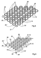
- the wall structure 4 includes a plurality of fuel ports 14 through which in the operation of the burner 2 fuel in the combustion chamber 3 can be initiated. Furthermore, the wall structure 4 contains a plurality of oxidant openings 15, which are separate relative to the fuel openings 14, through which the oxidizer can be introduced into the combustion chamber 3 during operation of the burner 2.
- the fuel openings 14 and the oxidizer openings 15 lie in one plane in the preferred embodiment shown here.
- this plane extends perpendicular to the direction of flow of fuel and oxidizer into the combustion chamber 3.
- FIG. 1 to 3 also show a particularly advantageous variant of the burner 2, since here the combustion chamber 3 is also enclosed laterally in addition to the outer wall 6 located outside with an inner inner wall 16.
- the inner wall 16 extends substantially parallel to the outer wall 6 and is arranged at a distance from the outer wall 6, so that between inner wall 16 and outer wall 6 a cooling space 17 is formed.
- This cooling space 17 surrounds the combustion chamber 3 in the circumferential direction, in particular completely.
- This cooling space 17 is charged during operation of the burner 2 with a cooling gas, whereby the inner wall 16 and in particular the outer wall 6 can be effectively cooled.
- the oxidizer is preferably used, which is introduced for this purpose via a plurality of oxidant openings 15 on the input side into the cooling space 17.
- the cooling space 17 is connected on the input side to a plurality of oxidizer openings 15.
- the inner wall 16 is not fully brought up to the heat exchanger 5, so that at the free end of the inner wall 16 of the used for cooling oxidizer can flow from the refrigerator 17 into the combustion chamber 3 ,
- this cooling gas can be used for afterburning.
- an additional line 27 is also connected to the cavity 22, through which, if necessary, additional oxidizer, e.g. cold air, the cavity 22 and thus the combustion chamber 3 can be supplied.
- additional oxidizer e.g. cold air
- the wall structure 4 is preferably provided with a base plate 19 and a cover plate 20.
- the cover plate 20 is on a side facing the combustion chamber 3 of the base plate 19 arranged.
- the cover plate 20 includes at least a plurality of first passage openings 21, which coincide in the embodiments of FIGS. 1 to 5 with the oxidizer 15 or form these.
- a cavity 22 is formed between the cover plate 20 and the base plate 19.
- this cavity 22 is connected to the Oxidatorpfad 13, whereby the oxidizer-product gas mixture, leaving the fuel cell 8 cathode side, in the cavity 22 passes and passes from this through the first passage openings 21, so through the oxidizer 15 into the combustion chamber 3.
- the base plate 19 is also equipped with a plurality of passage openings 23.
- the base plate 19 separates the cavity 22 from a feed space 24, with which the passage openings 23 of the base plate 19 communicate.
- These passage openings 23 are also connected to the fuel ports 14, which, however, explained in more detail below.
- the feed space 24 is connected to the fuel path 12 of the fuel cell 8. Accordingly, the hydrogen-product gas mixture emerging from the fuel cell 8 on the anode side enters the supply chamber 24 and out of the through-openings 23 of the base plate 19 and through the fuel openings 14 in the combustion chamber 3 a.
- the oxidizer supplied via the cavity 22 can be reliably separated from the fuel supplied via the feed space 24 until it enters the combustion chamber 3.
- FIGS. 1 to 5 is a particular embodiment in which the passage openings 23 of the base plate 19 are arranged coaxially with the first passage openings 21 of the cover plate 20.
- the coaxial alignment during operation of the burner 2 causes the fuel gas supplied via the supply chamber 24, as well as the oxidant gas supplied via the cavity 22, to enter the combustion chamber 3 directly or indirectly through the first passage opening 21 of the cover plate 20 in such a way that it is thereby enveloped by the over the cavity 22 supplied oxidizer gas.
- the introduction of the gases thus takes place coaxially with each other at each first passage opening 21 of the cover plate 20. In this way, a particularly intensive mixing of oxidizer and fuel can be achieved.
- the first passage openings 21 of the cover plate 20 are expediently equipped with a larger cross-section than the respective associated passage openings 23 of the base plate 19th
- the coating of the fuel gas with the oxidizer gas can already take place in the cavity 22 when the fuel gas first has to flow through the passage openings of the base plate 19 to pass through to the respectively assigned first passage opening 21 of the cover plate 20.
- the embodiment shown here is preferred, in which several or all passage openings 23 of the base plate 19 are each surrounded by a sleeve 25. These sleeves 25 are from the base plate 19, protrude into the cavity 22 in. Furthermore, the sleeves 25 provided for supplying the fuel are open at their end remote from the base plate 19, this open end forming the respective fuel opening 14.
- the sleeves 25 are also dimensioned such that they extend through the respectively associated first passage opening 21 of the cover plate 20 or extend so far therethrough until they are flush with the cover plate 20.
- longer sleeves 25 or shorter sleeves 25 are conceivable.
- This construction ensures that an annular gap 26 is formed in the respective sleeves 25 radially between the sleeve 25 and an opening edge of the respectively associated first nozzle opening 21 of the cover plate 20.
- the gas supplied via the cavity 22 can therefore enter the combustion chamber 3 through this annular gap 26, in this case the oxidizer.
- the sleeves 25 are integrally formed on the base plate 19, z. B. by deep drawing of the base plate 19, wherein at the same time the openings 23 and 14 can be formed.
- separate sleeves 25 are conceivable, which are then connected to the base plate 19 in a suitable manner.
- the oxidizer is supplied to the cavity 22 and the fuel to the feed space 24, in principle, a reverse flow guide is possible, so that then the oxidizer is supplied to the feed space 24, while the fuel is supplied to the cavity 22.
- FIG. 5 again shows a perspective view of a detail of the wall structure, on the side facing the combustion chamber 3.
- the sleeves 25, which protrude into the first passage openings 21 of the cover plate 20 and thereby form the annular gaps 26 are also visible.
- the externally arranged closed sleeves 25 'are provided for positioning in the cooling space 17, for example.
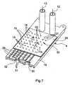
- FIG. 6 now shows another embodiment in which the cover plate 20 additionally contains a plurality of second passage openings 28.
- These second passage openings 28 of the cover plate 20 are aligned coaxially with the passage openings 23 of the base plate 19.
- the fuel initially passes through the passage openings 23 of the base plate 19 and then through the second passage openings 28 of the cover plate 20 in order to reach the combustion chamber 3.
- the oxidizer enters through the first passage openings 21 of the cover plate 20 directly into the combustion chamber 3.
- the sleeves 25 extend from the cover plate 20 and extend into a correspondingly dimensioned passage opening 23 of the base plate 19 tightly.
- the sleeves 25 may be plugged into both the base plate 19 and in the cover plate 20 or be radially overlapped both from the cover plate 20 and from the base plate 19 frontally.
- FIG. 6 also shows exemplary closed sleeves 25 ", which are pressed together with the second passage openings 28 'in order to fix the cover plate 20 to the base plate 19.
- an oxidant channel system 29 may be incorporated in the baseplate 19 which is suitably connected to an oxidizer feeder 30.
- a fuel channel system 31, which is connected to a fuel feed 32, is also incorporated into the base plate 19 in this embodiment. While the oxidant channel system 29 communicates with the oxidizer ports 15, the fuel channel system 31 is connected to the fuel ports 14.
- the individual channels of the channel systems 29 and 31 are incorporated at the combustion chamber 3 side facing in the base plate 19, for example milled or embossed. The channels are thus open to the combustion chamber 3. Through the cover plate 20, however, they are hidden, wherein the cover plate 20 is again provided with the first passage opening 21, which form a hole pattern 33 here.
- This hole pattern 33 is matched to the channel systems 29, 31 so that the first passage openings 21 of the cover 20 come to rest on the individual channels of the channel systems 29, 31 and thereby form the fuel openings 14 and the oxidizer 15.
- the fuel supply 32 is connected in the installed state to the fuel path 12 of the fuel cell 8, while the Oxidatorzu arrangement 30 is connected to the Oxidatorpfad 13 of the fuel cell 8.
- the burner 2 expediently comprises an ignition device, not shown, as well as a sensor, not shown, in particular for measuring temperatures, pressures and / or emissions.
Landscapes
- Engineering & Computer Science (AREA)
- Chemical & Material Sciences (AREA)
- Combustion & Propulsion (AREA)
- Sustainable Development (AREA)
- Sustainable Energy (AREA)
- Life Sciences & Earth Sciences (AREA)
- Chemical Kinetics & Catalysis (AREA)
- Electrochemistry (AREA)
- General Chemical & Material Sciences (AREA)
- Manufacturing & Machinery (AREA)
- Mechanical Engineering (AREA)
- General Engineering & Computer Science (AREA)
- Fuel Cell (AREA)
- Gas Burners (AREA)
- Pre-Mixing And Non-Premixing Gas Burner (AREA)
Applications Claiming Priority (1)
| Application Number | Priority Date | Filing Date | Title |
|---|---|---|---|
| DE102004033545A DE102004033545B4 (de) | 2004-07-09 | 2004-07-09 | Brenner |
Publications (4)
| Publication Number | Publication Date |
|---|---|
| EP1614964A2 true EP1614964A2 (fr) | 2006-01-11 |
| EP1614964A8 EP1614964A8 (fr) | 2006-03-29 |
| EP1614964A3 EP1614964A3 (fr) | 2006-10-11 |
| EP1614964B1 EP1614964B1 (fr) | 2013-09-11 |
Family
ID=34993313
Family Applications (1)
| Application Number | Title | Priority Date | Filing Date |
|---|---|---|---|
| EP05105235.5A Expired - Lifetime EP1614964B1 (fr) | 2004-07-09 | 2005-06-15 | Brûleur |
Country Status (6)
| Country | Link |
|---|---|
| US (1) | US7677884B2 (fr) |
| EP (1) | EP1614964B1 (fr) |
| JP (1) | JP4732816B2 (fr) |
| KR (1) | KR101125877B1 (fr) |
| CN (1) | CN100567817C (fr) |
| DE (1) | DE102004033545B4 (fr) |
Cited By (1)
| Publication number | Priority date | Publication date | Assignee | Title |
|---|---|---|---|---|
| WO2007128963A1 (fr) * | 2006-05-05 | 2007-11-15 | Rolls-Royce Fuel Cell Systems Limited | Brûleur a combustible et procédé de fabrication de celui-ci |
Families Citing this family (22)
| Publication number | Priority date | Publication date | Assignee | Title |
|---|---|---|---|---|
| DE102006010375B4 (de) * | 2006-03-03 | 2008-01-17 | J. Eberspächer GmbH & Co. KG | Wandstruktur für einen Brenner |
| DE102006024574A1 (de) | 2006-05-23 | 2007-11-29 | J. Eberspächer GmbH & Co. KG | Brenner und damit ausgestattetes Brennstoffzellensystem |
| DE102006046256A1 (de) * | 2006-09-28 | 2008-04-03 | J. Eberspächer GmbH & Co. KG | Wasserstoffheizung |
| DE102006046257A1 (de) * | 2006-09-28 | 2008-04-10 | J. Eberspächer GmbH & Co. KG | Brennstoffzellensystem |
| DE102006046255A1 (de) | 2006-09-28 | 2008-04-03 | J. Eberspächer GmbH & Co. KG | Brenneranordnung |
| DE102006046258A1 (de) * | 2006-09-28 | 2008-04-10 | J. Eberspächer GmbH & Co. KG | Brennstoffzellensystem |
| FR2919348A1 (fr) * | 2007-07-23 | 2009-01-30 | Centre Nat Rech Scient | Dispositif d'injection d'un combustible ou d'un pre-melange combustible/comburant comprenant des moyens permettant un controle passif des instabilites de combustion |
| DE102008009063A1 (de) | 2008-02-13 | 2009-08-20 | J. Eberspächer GmbH & Co. KG | Brennstoffzellensystem |
| DE102008019854A1 (de) | 2008-04-23 | 2009-10-29 | J. Eberspächer GmbH & Co. KG | Wandstruktur und Brenner sowie System |
| DE102008063540B4 (de) * | 2008-12-10 | 2024-02-22 | Eberspächer Climate Control Systems GmbH & Co. KG | Modulares Brennstoffzellensystem |
| DE102008063101A1 (de) * | 2008-12-24 | 2010-07-01 | Messer Austria Gmbh | Flachflammenbrenner und Verfahren zum Betreiben eines Flachflammenbrenners |
| JP5812379B2 (ja) | 2010-07-02 | 2015-11-11 | スズキ株式会社 | 燃料電池車両の暖房装置 |
| DE102010039022B4 (de) | 2010-08-06 | 2022-08-11 | Eberspächer Climate Control Systems GmbH & Co. KG | Brenner und Brennstoffzellensystem |
| DE102011087971B4 (de) | 2011-12-08 | 2021-03-04 | Eberspächer Climate Control Systems GmbH | Verfahren zum Betreiben eines mit Kohlenwasserstoff-Brennstoff betreibbaren Heizgeräts |
| CA2862808A1 (fr) * | 2012-02-22 | 2013-08-29 | Clearsign Combustion Corporation | Electrode refroidie et systeme de bruleur comprenant une electrode refroidie |
| DE102013203316A1 (de) * | 2013-02-27 | 2014-08-28 | Bayerische Motoren Werke Aktiengesellschaft | Brennstoffzellensystem |
| JPWO2014199658A1 (ja) * | 2013-06-13 | 2017-02-23 | 株式会社村田製作所 | 燃料電池モジュール |
| DE102013216127B4 (de) * | 2013-08-14 | 2015-03-19 | Eberspächer Climate Control Systems GmbH & Co. KG | Strömungsverdämmungselement, insbesondere zur Luftströmungsverdämmung in einem Luftkanalsystem eines Fahrzeugs |
| JP6684022B2 (ja) * | 2016-03-31 | 2020-04-22 | 本田技研工業株式会社 | 燃料電池モジュール |
| EP4158247B1 (fr) | 2020-06-29 | 2023-11-01 | AMF Den Boer B.V. | Brûleur à gaz hydrogène |
| DE102020212393B3 (de) | 2020-09-30 | 2021-12-30 | Siemens Mobility GmbH | Fahrzeug mit katalytischem Brenner zur Klimatisierung eines Fahrgastraums |
| CN116857644B (zh) * | 2023-07-07 | 2024-02-09 | 中国矿业大学 | 一种低浓度瓦斯掺杂氢气燃烧装置及方法 |
Citations (4)
| Publication number | Priority date | Publication date | Assignee | Title |
|---|---|---|---|---|
| DE4217892A1 (de) | 1991-05-30 | 1992-12-03 | Fuji Electric Co Ltd | Energieerzeugungssystem mit einer festkoerperelektrolyt-brennstoffzellenanordnung sowie energieerzeugungsmodul und dichtvorrichtung fuer ein solches system |
| US5292246A (en) | 1988-05-02 | 1994-03-08 | Institut Francais Du Petrole | Burner for the manufacture of synthetic gas comprising a solid element with holes |
| US6033793A (en) | 1996-11-01 | 2000-03-07 | Hydrogen Burner Technology, Inc. | Integrated power module |
| DE10149329A1 (de) | 2001-10-06 | 2003-04-24 | Bosch Gmbh Robert | Integrierter rekuperativer Brenner |
Family Cites Families (17)
| Publication number | Priority date | Publication date | Assignee | Title |
|---|---|---|---|---|
| US3909299A (en) * | 1973-10-01 | 1975-09-30 | United Technologies Corp | Fuel cell system including reform reactor |
| CS551787A1 (en) * | 1986-11-18 | 1989-05-12 | Schingnitz Manfred | Gas burner |
| JPH01249601A (ja) * | 1988-03-29 | 1989-10-04 | Mitsubishi Electric Corp | 燃料電池発電装置の改質器用燃焼装置 |
| JPH07109773B2 (ja) * | 1989-02-28 | 1995-11-22 | 石川島播磨重工業株式会社 | 燃料電池を用いた発電装置 |
| JPH09249402A (ja) * | 1996-03-15 | 1997-09-22 | Mitsubishi Electric Corp | 改質装置 |
| DE19618220A1 (de) * | 1996-05-07 | 1997-11-13 | Bosch Gmbh Robert | Vorrichtung zur Erzeugung von Wärme und zur elektrochemischen Stromerzeugung |
| JPH10177864A (ja) * | 1996-10-18 | 1998-06-30 | Toshiba Corp | 燃料電池 |
| US5803725A (en) * | 1997-06-13 | 1998-09-08 | Horn; Wallace E. | Triple-mix surface-mix burner |
| US6296814B1 (en) * | 1998-11-10 | 2001-10-02 | International Fuel Cells, L.L.C. | Hydrocarbon fuel gas reformer assembly for a fuel cell power plant |
| US20020064487A1 (en) * | 2000-11-30 | 2002-05-30 | Richard Sederquist | Compact Multiple tube steam reformer |
| JP3913996B2 (ja) * | 2001-02-26 | 2007-05-09 | 三洋電機株式会社 | 改質器用バーナ装置 |
| US6596424B2 (en) * | 2001-03-30 | 2003-07-22 | General Motors Corporation | Apparatus for mixing fuel and an oxidant |
| JP2003238132A (ja) * | 2002-02-12 | 2003-08-27 | Mitsubishi Chemicals Corp | フラーレン類の製造用バーナー及びこれを用いたフラーレン類の製造方法 |
| JP3854170B2 (ja) | 2002-02-21 | 2006-12-06 | 京セラ株式会社 | 燃料電池 |
| US20030223926A1 (en) * | 2002-04-14 | 2003-12-04 | Edlund David J. | Steam reforming fuel processor, burner assembly, and methods of operating the same |
| JP2004093118A (ja) * | 2002-08-09 | 2004-03-25 | Jfe Steel Kk | 管状火炎バ−ナ |
| DE10244883B4 (de) * | 2002-09-26 | 2005-02-17 | J. Eberspächer GmbH & Co. KG | Heizsystem für ein Fahrzeug |
-
2004
- 2004-07-09 DE DE102004033545A patent/DE102004033545B4/de not_active Expired - Fee Related
-
2005
- 2005-06-15 EP EP05105235.5A patent/EP1614964B1/fr not_active Expired - Lifetime
- 2005-06-29 KR KR1020050056639A patent/KR101125877B1/ko not_active Expired - Fee Related
- 2005-07-08 US US11/178,221 patent/US7677884B2/en active Active - Reinstated
- 2005-07-11 JP JP2005201345A patent/JP4732816B2/ja not_active Expired - Lifetime
- 2005-07-11 CN CNB2005100844487A patent/CN100567817C/zh not_active Expired - Fee Related
Patent Citations (4)
| Publication number | Priority date | Publication date | Assignee | Title |
|---|---|---|---|---|
| US5292246A (en) | 1988-05-02 | 1994-03-08 | Institut Francais Du Petrole | Burner for the manufacture of synthetic gas comprising a solid element with holes |
| DE4217892A1 (de) | 1991-05-30 | 1992-12-03 | Fuji Electric Co Ltd | Energieerzeugungssystem mit einer festkoerperelektrolyt-brennstoffzellenanordnung sowie energieerzeugungsmodul und dichtvorrichtung fuer ein solches system |
| US6033793A (en) | 1996-11-01 | 2000-03-07 | Hydrogen Burner Technology, Inc. | Integrated power module |
| DE10149329A1 (de) | 2001-10-06 | 2003-04-24 | Bosch Gmbh Robert | Integrierter rekuperativer Brenner |
Cited By (1)
| Publication number | Priority date | Publication date | Assignee | Title |
|---|---|---|---|---|
| WO2007128963A1 (fr) * | 2006-05-05 | 2007-11-15 | Rolls-Royce Fuel Cell Systems Limited | Brûleur a combustible et procédé de fabrication de celui-ci |
Also Published As
| Publication number | Publication date |
|---|---|
| DE102004033545B4 (de) | 2006-06-14 |
| CN100567817C (zh) | 2009-12-09 |
| CN1737426A (zh) | 2006-02-22 |
| US7677884B2 (en) | 2010-03-16 |
| EP1614964A3 (fr) | 2006-10-11 |
| EP1614964B1 (fr) | 2013-09-11 |
| JP2006023077A (ja) | 2006-01-26 |
| KR101125877B1 (ko) | 2012-03-21 |
| KR20060048649A (ko) | 2006-05-18 |
| US20060008756A1 (en) | 2006-01-12 |
| JP4732816B2 (ja) | 2011-07-27 |
| EP1614964A8 (fr) | 2006-03-29 |
| DE102004033545A1 (de) | 2006-02-02 |
Similar Documents
| Publication | Publication Date | Title |
|---|---|---|
| EP1614964B1 (fr) | Brûleur | |
| DE102007039594B4 (de) | Energieerzeugungseinheit mit zumindest einer Hochtemperaturbrennstoffzelle | |
| EP1616361B1 (fr) | Dispositif de conversion de l'energie avec installation de reformage et installation de pile a combustible associees | |
| WO2004020905A1 (fr) | Procede et dispositif pour faire bruler un melange combustible-oxydant | |
| DE102008018152B4 (de) | Brennstoffzellensystem und zugehöriges Betriebsverfahren | |
| DE102008063540A1 (de) | Modulares Brennstoffzellensystem | |
| EP1679757B1 (fr) | Système de pile à combustible | |
| EP1830128B1 (fr) | Paroi de brûleur | |
| EP1845576B1 (fr) | Système de cellules combustibles | |
| DE10393240T5 (de) | Autothermer Reformer mit mehreren Durchlässen | |
| EP1619737B1 (fr) | Système de pile à combustible, postbrûleur et échangeur de chaleur | |
| EP1919018B1 (fr) | Système de pile à combustible | |
| EP1860378B1 (fr) | Brûleur et système de pile à combustible associé | |
| DE102021126708B3 (de) | Verfahren zum Starten einer Festoxidbrennstoffzellenvorrichtung sowie Brennstoffzellenfahrzeug | |
| DE102008009063A1 (de) | Brennstoffzellensystem | |
| EP2028709A1 (fr) | Système de pile à combustible | |
| DE102010039022B4 (de) | Brenner und Brennstoffzellensystem | |
| DE102008017237B4 (de) | Reformer und Brennstoffzellensystem | |
| EP1739777B1 (fr) | Système de pile à combustible pour véhicules | |
| EP1845577A2 (fr) | Système de pile à combustible | |
| EP1968150B1 (fr) | Système de piles à combustibles | |
| EP2075225B1 (fr) | Dispositif de reformage, système de piles à combustibles et procédé d'opération du système | |
| AT523317B1 (de) | Aufheizvorrichtung für ein Aufheizen eines Brennstoffzellenstapels | |
| DE10247521A1 (de) | Brennstoffzellensystem | |
| WO2003072234A1 (fr) | Systeme pour transformer un combustible et de l'air en un reformat |
Legal Events
| Date | Code | Title | Description |
|---|---|---|---|
| PUAI | Public reference made under article 153(3) epc to a published international application that has entered the european phase |
Free format text: ORIGINAL CODE: 0009012 |
|
| AK | Designated contracting states |
Kind code of ref document: A2 Designated state(s): AT BE BG CH CY CZ DE DK EE ES FI FR GB GR HU IE IS IT LI LT LU MC NL PL PT RO SE SI SK TR |
|
| AX | Request for extension of the european patent |
Extension state: AL BA HR LV MK YU |
|
| RAP1 | Party data changed (applicant data changed or rights of an application transferred) |
Owner name: J. EBERSPAECHER GMBH & CO. KG |
|
| PUAL | Search report despatched |
Free format text: ORIGINAL CODE: 0009013 |
|
| AK | Designated contracting states |
Kind code of ref document: A3 Designated state(s): AT BE BG CH CY CZ DE DK EE ES FI FR GB GR HU IE IS IT LI LT LU MC NL PL PT RO SE SI SK TR |
|
| AX | Request for extension of the european patent |
Extension state: AL BA HR LV MK YU |
|
| RIC1 | Information provided on ipc code assigned before grant |
Ipc: H01M 8/06 20060101AFI20060901BHEP Ipc: F23D 14/22 20060101ALI20060901BHEP |
|
| 17P | Request for examination filed |
Effective date: 20070411 |
|
| AKX | Designation fees paid |
Designated state(s): AT BE BG CH CY CZ DE DK EE ES FI FR GB GR HU IE IS IT LI LT LU MC NL PL PT RO SE SI SK TR |
|
| 17Q | First examination report despatched |
Effective date: 20090619 |
|
| GRAP | Despatch of communication of intention to grant a patent |
Free format text: ORIGINAL CODE: EPIDOSNIGR1 |
|
| GRAS | Grant fee paid |
Free format text: ORIGINAL CODE: EPIDOSNIGR3 |
|
| GRAA | (expected) grant |
Free format text: ORIGINAL CODE: 0009210 |
|
| AK | Designated contracting states |
Kind code of ref document: B1 Designated state(s): AT BE BG CH CY CZ DE DK EE ES FI FR GB GR HU IE IS IT LI LT LU MC NL PL PT RO SE SI SK TR |
|
| REG | Reference to a national code |
Ref country code: GB Ref legal event code: FG4D Free format text: NOT ENGLISH |
|
| REG | Reference to a national code |
Ref country code: CH Ref legal event code: EP |
|
| REG | Reference to a national code |
Ref country code: AT Ref legal event code: REF Ref document number: 632069 Country of ref document: AT Kind code of ref document: T Effective date: 20130915 |
|
| REG | Reference to a national code |
Ref country code: IE Ref legal event code: FG4D Free format text: LANGUAGE OF EP DOCUMENT: GERMAN |
|
| RAP2 | Party data changed (patent owner data changed or rights of a patent transferred) |
Owner name: EBERSPAECHER CLIMATE CONTROL SYSTEMS GMBH & CO. KG |
|
| REG | Reference to a national code |
Ref country code: DE Ref legal event code: R096 Ref document number: 502005013966 Country of ref document: DE Effective date: 20131107 |
|
| REG | Reference to a national code |
Ref country code: NL Ref legal event code: T3 |
|
| REG | Reference to a national code |
Ref country code: SE Ref legal event code: TRGR |
|
| PG25 | Lapsed in a contracting state [announced via postgrant information from national office to epo] |
Ref country code: LT Free format text: LAPSE BECAUSE OF FAILURE TO SUBMIT A TRANSLATION OF THE DESCRIPTION OR TO PAY THE FEE WITHIN THE PRESCRIBED TIME-LIMIT Effective date: 20130911 Ref country code: CY Free format text: LAPSE BECAUSE OF FAILURE TO SUBMIT A TRANSLATION OF THE DESCRIPTION OR TO PAY THE FEE WITHIN THE PRESCRIBED TIME-LIMIT Effective date: 20130703 |
|
| REG | Reference to a national code |
Ref country code: LT Ref legal event code: MG4D |
|
| PG25 | Lapsed in a contracting state [announced via postgrant information from national office to epo] |
Ref country code: GR Free format text: LAPSE BECAUSE OF FAILURE TO SUBMIT A TRANSLATION OF THE DESCRIPTION OR TO PAY THE FEE WITHIN THE PRESCRIBED TIME-LIMIT Effective date: 20131212 Ref country code: FI Free format text: LAPSE BECAUSE OF FAILURE TO SUBMIT A TRANSLATION OF THE DESCRIPTION OR TO PAY THE FEE WITHIN THE PRESCRIBED TIME-LIMIT Effective date: 20130911 Ref country code: ES Free format text: LAPSE BECAUSE OF FAILURE TO SUBMIT A TRANSLATION OF THE DESCRIPTION OR TO PAY THE FEE WITHIN THE PRESCRIBED TIME-LIMIT Effective date: 20130911 Ref country code: SI Free format text: LAPSE BECAUSE OF FAILURE TO SUBMIT A TRANSLATION OF THE DESCRIPTION OR TO PAY THE FEE WITHIN THE PRESCRIBED TIME-LIMIT Effective date: 20130911 |
|
| PG25 | Lapsed in a contracting state [announced via postgrant information from national office to epo] |
Ref country code: CY Free format text: LAPSE BECAUSE OF FAILURE TO SUBMIT A TRANSLATION OF THE DESCRIPTION OR TO PAY THE FEE WITHIN THE PRESCRIBED TIME-LIMIT Effective date: 20130911 |
|
| PG25 | Lapsed in a contracting state [announced via postgrant information from national office to epo] |
Ref country code: SK Free format text: LAPSE BECAUSE OF FAILURE TO SUBMIT A TRANSLATION OF THE DESCRIPTION OR TO PAY THE FEE WITHIN THE PRESCRIBED TIME-LIMIT Effective date: 20130911 Ref country code: CZ Free format text: LAPSE BECAUSE OF FAILURE TO SUBMIT A TRANSLATION OF THE DESCRIPTION OR TO PAY THE FEE WITHIN THE PRESCRIBED TIME-LIMIT Effective date: 20130911 Ref country code: EE Free format text: LAPSE BECAUSE OF FAILURE TO SUBMIT A TRANSLATION OF THE DESCRIPTION OR TO PAY THE FEE WITHIN THE PRESCRIBED TIME-LIMIT Effective date: 20130911 Ref country code: RO Free format text: LAPSE BECAUSE OF FAILURE TO SUBMIT A TRANSLATION OF THE DESCRIPTION OR TO PAY THE FEE WITHIN THE PRESCRIBED TIME-LIMIT Effective date: 20130911 Ref country code: IS Free format text: LAPSE BECAUSE OF FAILURE TO SUBMIT A TRANSLATION OF THE DESCRIPTION OR TO PAY THE FEE WITHIN THE PRESCRIBED TIME-LIMIT Effective date: 20140111 |
|
| PG25 | Lapsed in a contracting state [announced via postgrant information from national office to epo] |
Ref country code: PL Free format text: LAPSE BECAUSE OF FAILURE TO SUBMIT A TRANSLATION OF THE DESCRIPTION OR TO PAY THE FEE WITHIN THE PRESCRIBED TIME-LIMIT Effective date: 20130911 |
|
| REG | Reference to a national code |
Ref country code: DE Ref legal event code: R097 Ref document number: 502005013966 Country of ref document: DE |
|
| PG25 | Lapsed in a contracting state [announced via postgrant information from national office to epo] |
Ref country code: PT Free format text: LAPSE BECAUSE OF FAILURE TO SUBMIT A TRANSLATION OF THE DESCRIPTION OR TO PAY THE FEE WITHIN THE PRESCRIBED TIME-LIMIT Effective date: 20140113 |
|
| PLBE | No opposition filed within time limit |
Free format text: ORIGINAL CODE: 0009261 |
|
| STAA | Information on the status of an ep patent application or granted ep patent |
Free format text: STATUS: NO OPPOSITION FILED WITHIN TIME LIMIT |
|
| 26N | No opposition filed |
Effective date: 20140612 |
|
| REG | Reference to a national code |
Ref country code: DE Ref legal event code: R097 Ref document number: 502005013966 Country of ref document: DE Effective date: 20140612 |
|
| PG25 | Lapsed in a contracting state [announced via postgrant information from national office to epo] |
Ref country code: DK Free format text: LAPSE BECAUSE OF FAILURE TO SUBMIT A TRANSLATION OF THE DESCRIPTION OR TO PAY THE FEE WITHIN THE PRESCRIBED TIME-LIMIT Effective date: 20130911 |
|
| PG25 | Lapsed in a contracting state [announced via postgrant information from national office to epo] |
Ref country code: MC Free format text: LAPSE BECAUSE OF FAILURE TO SUBMIT A TRANSLATION OF THE DESCRIPTION OR TO PAY THE FEE WITHIN THE PRESCRIBED TIME-LIMIT Effective date: 20130911 Ref country code: SE Free format text: LAPSE BECAUSE OF NON-PAYMENT OF DUE FEES Effective date: 20140616 Ref country code: LU Free format text: LAPSE BECAUSE OF FAILURE TO SUBMIT A TRANSLATION OF THE DESCRIPTION OR TO PAY THE FEE WITHIN THE PRESCRIBED TIME-LIMIT Effective date: 20140615 |
|
| REG | Reference to a national code |
Ref country code: CH Ref legal event code: PL |
|
| REG | Reference to a national code |
Ref country code: SE Ref legal event code: EUG |
|
| REG | Reference to a national code |
Ref country code: IE Ref legal event code: MM4A |
|
| REG | Reference to a national code |
Ref country code: FR Ref legal event code: ST Effective date: 20150227 |
|
| PG25 | Lapsed in a contracting state [announced via postgrant information from national office to epo] |
Ref country code: NL Free format text: LAPSE BECAUSE OF NON-PAYMENT OF DUE FEES Effective date: 20150101 |
|
| PG25 | Lapsed in a contracting state [announced via postgrant information from national office to epo] |
Ref country code: IT Free format text: LAPSE BECAUSE OF NON-PAYMENT OF DUE FEES Effective date: 20140615 Ref country code: LI Free format text: LAPSE BECAUSE OF NON-PAYMENT OF DUE FEES Effective date: 20140630 Ref country code: IE Free format text: LAPSE BECAUSE OF NON-PAYMENT OF DUE FEES Effective date: 20140615 Ref country code: CH Free format text: LAPSE BECAUSE OF NON-PAYMENT OF DUE FEES Effective date: 20140630 |
|
| PG25 | Lapsed in a contracting state [announced via postgrant information from national office to epo] |
Ref country code: FR Free format text: LAPSE BECAUSE OF NON-PAYMENT OF DUE FEES Effective date: 20140630 |
|
| REG | Reference to a national code |
Ref country code: AT Ref legal event code: MM01 Ref document number: 632069 Country of ref document: AT Kind code of ref document: T Effective date: 20140615 |
|
| PG25 | Lapsed in a contracting state [announced via postgrant information from national office to epo] |
Ref country code: AT Free format text: LAPSE BECAUSE OF NON-PAYMENT OF DUE FEES Effective date: 20140615 |
|
| PG25 | Lapsed in a contracting state [announced via postgrant information from national office to epo] |
Ref country code: BG Free format text: LAPSE BECAUSE OF FAILURE TO SUBMIT A TRANSLATION OF THE DESCRIPTION OR TO PAY THE FEE WITHIN THE PRESCRIBED TIME-LIMIT Effective date: 20130911 |
|
| PG25 | Lapsed in a contracting state [announced via postgrant information from national office to epo] |
Ref country code: HU Free format text: LAPSE BECAUSE OF FAILURE TO SUBMIT A TRANSLATION OF THE DESCRIPTION OR TO PAY THE FEE WITHIN THE PRESCRIBED TIME-LIMIT; INVALID AB INITIO Effective date: 20050615 Ref country code: BE Free format text: LAPSE BECAUSE OF FAILURE TO SUBMIT A TRANSLATION OF THE DESCRIPTION OR TO PAY THE FEE WITHIN THE PRESCRIBED TIME-LIMIT Effective date: 20140630 Ref country code: TR Free format text: LAPSE BECAUSE OF FAILURE TO SUBMIT A TRANSLATION OF THE DESCRIPTION OR TO PAY THE FEE WITHIN THE PRESCRIBED TIME-LIMIT Effective date: 20130911 |
|
| PGFP | Annual fee paid to national office [announced via postgrant information from national office to epo] |
Ref country code: GB Payment date: 20220623 Year of fee payment: 18 Ref country code: DE Payment date: 20220630 Year of fee payment: 18 |
|
| REG | Reference to a national code |
Ref country code: DE Ref legal event code: R119 Ref document number: 502005013966 Country of ref document: DE |
|
| GBPC | Gb: european patent ceased through non-payment of renewal fee |
Effective date: 20230615 |
|
| PG25 | Lapsed in a contracting state [announced via postgrant information from national office to epo] |
Ref country code: DE Free format text: LAPSE BECAUSE OF NON-PAYMENT OF DUE FEES Effective date: 20240103 Ref country code: GB Free format text: LAPSE BECAUSE OF NON-PAYMENT OF DUE FEES Effective date: 20230615 |