EP1615199A2 - Plasmaanzeigegerät und Bildverarbeitungsverfahren dafür - Google Patents
Plasmaanzeigegerät und Bildverarbeitungsverfahren dafür Download PDFInfo
- Publication number
- EP1615199A2 EP1615199A2 EP05014651A EP05014651A EP1615199A2 EP 1615199 A2 EP1615199 A2 EP 1615199A2 EP 05014651 A EP05014651 A EP 05014651A EP 05014651 A EP05014651 A EP 05014651A EP 1615199 A2 EP1615199 A2 EP 1615199A2
- Authority
- EP
- European Patent Office
- Prior art keywords
- plasma display
- display apparatus
- error diffusion
- bit
- image
- Prior art date
- Legal status (The legal status is an assumption and is not a legal conclusion. Google has not performed a legal analysis and makes no representation as to the accuracy of the status listed.)
- Withdrawn
Links
- 238000003672 processing method Methods 0.000 title abstract description 8
- 238000009792 diffusion process Methods 0.000 claims abstract description 150
- 238000013507 mapping Methods 0.000 claims abstract description 16
- 238000012937 correction Methods 0.000 claims abstract description 14
- 238000000034 method Methods 0.000 claims description 42
- 238000012545 processing Methods 0.000 claims description 13
- 238000007796 conventional method Methods 0.000 description 6
- 230000015572 biosynthetic process Effects 0.000 description 3
- 239000007789 gas Substances 0.000 description 3
- 239000004973 liquid crystal related substance Substances 0.000 description 3
- 238000010586 diagram Methods 0.000 description 2
- 239000011261 inert gas Substances 0.000 description 2
- 239000000758 substrate Substances 0.000 description 2
- 230000002708 enhancing effect Effects 0.000 description 1
- 229910052734 helium Inorganic materials 0.000 description 1
- 239000001307 helium Substances 0.000 description 1
- SWQJXJOGLNCZEY-UHFFFAOYSA-N helium atom Chemical compound [He] SWQJXJOGLNCZEY-UHFFFAOYSA-N 0.000 description 1
- 239000011159 matrix material Substances 0.000 description 1
- 239000000203 mixture Substances 0.000 description 1
- 238000012986 modification Methods 0.000 description 1
- 230000004048 modification Effects 0.000 description 1
- 229910052754 neon Inorganic materials 0.000 description 1
- GKAOGPIIYCISHV-UHFFFAOYSA-N neon atom Chemical compound [Ne] GKAOGPIIYCISHV-UHFFFAOYSA-N 0.000 description 1
- 239000000126 substance Substances 0.000 description 1
- 229910052724 xenon Inorganic materials 0.000 description 1
- FHNFHKCVQCLJFQ-UHFFFAOYSA-N xenon atom Chemical compound [Xe] FHNFHKCVQCLJFQ-UHFFFAOYSA-N 0.000 description 1
Images



Classifications
-
- G—PHYSICS
- G09—EDUCATION; CRYPTOGRAPHY; DISPLAY; ADVERTISING; SEALS
- G09G—ARRANGEMENTS OR CIRCUITS FOR CONTROL OF INDICATING DEVICES USING STATIC MEANS TO PRESENT VARIABLE INFORMATION
- G09G3/00—Control arrangements or circuits, of interest only in connection with visual indicators other than cathode-ray tubes
- G09G3/20—Control arrangements or circuits, of interest only in connection with visual indicators other than cathode-ray tubes for presentation of an assembly of a number of characters, e.g. a page, by composing the assembly by combination of individual elements arranged in a matrix no fixed position being assigned to or needed to be assigned to the individual characters or partial characters
- G09G3/22—Control arrangements or circuits, of interest only in connection with visual indicators other than cathode-ray tubes for presentation of an assembly of a number of characters, e.g. a page, by composing the assembly by combination of individual elements arranged in a matrix no fixed position being assigned to or needed to be assigned to the individual characters or partial characters using controlled light sources
- G09G3/28—Control arrangements or circuits, of interest only in connection with visual indicators other than cathode-ray tubes for presentation of an assembly of a number of characters, e.g. a page, by composing the assembly by combination of individual elements arranged in a matrix no fixed position being assigned to or needed to be assigned to the individual characters or partial characters using controlled light sources using luminous gas-discharge panels, e.g. plasma panels
- G09G3/288—Control arrangements or circuits, of interest only in connection with visual indicators other than cathode-ray tubes for presentation of an assembly of a number of characters, e.g. a page, by composing the assembly by combination of individual elements arranged in a matrix no fixed position being assigned to or needed to be assigned to the individual characters or partial characters using controlled light sources using luminous gas-discharge panels, e.g. plasma panels using AC panels
- G09G3/296—Driving circuits for producing the waveforms applied to the driving electrodes
-
- G—PHYSICS
- G09—EDUCATION; CRYPTOGRAPHY; DISPLAY; ADVERTISING; SEALS
- G09G—ARRANGEMENTS OR CIRCUITS FOR CONTROL OF INDICATING DEVICES USING STATIC MEANS TO PRESENT VARIABLE INFORMATION
- G09G3/00—Control arrangements or circuits, of interest only in connection with visual indicators other than cathode-ray tubes
- G09G3/20—Control arrangements or circuits, of interest only in connection with visual indicators other than cathode-ray tubes for presentation of an assembly of a number of characters, e.g. a page, by composing the assembly by combination of individual elements arranged in a matrix no fixed position being assigned to or needed to be assigned to the individual characters or partial characters
- G09G3/2007—Display of intermediate tones
- G09G3/2059—Display of intermediate tones using error diffusion
-
- G—PHYSICS
- G09—EDUCATION; CRYPTOGRAPHY; DISPLAY; ADVERTISING; SEALS
- G09G—ARRANGEMENTS OR CIRCUITS FOR CONTROL OF INDICATING DEVICES USING STATIC MEANS TO PRESENT VARIABLE INFORMATION
- G09G3/00—Control arrangements or circuits, of interest only in connection with visual indicators other than cathode-ray tubes
- G09G3/20—Control arrangements or circuits, of interest only in connection with visual indicators other than cathode-ray tubes for presentation of an assembly of a number of characters, e.g. a page, by composing the assembly by combination of individual elements arranged in a matrix no fixed position being assigned to or needed to be assigned to the individual characters or partial characters
- G09G3/2007—Display of intermediate tones
- G09G3/2018—Display of intermediate tones by time modulation using two or more time intervals
- G09G3/2022—Display of intermediate tones by time modulation using two or more time intervals using sub-frames
-
- G—PHYSICS
- G09—EDUCATION; CRYPTOGRAPHY; DISPLAY; ADVERTISING; SEALS
- G09G—ARRANGEMENTS OR CIRCUITS FOR CONTROL OF INDICATING DEVICES USING STATIC MEANS TO PRESENT VARIABLE INFORMATION
- G09G3/00—Control arrangements or circuits, of interest only in connection with visual indicators other than cathode-ray tubes
- G09G3/20—Control arrangements or circuits, of interest only in connection with visual indicators other than cathode-ray tubes for presentation of an assembly of a number of characters, e.g. a page, by composing the assembly by combination of individual elements arranged in a matrix no fixed position being assigned to or needed to be assigned to the individual characters or partial characters
- G09G3/2007—Display of intermediate tones
- G09G3/2044—Display of intermediate tones using dithering
- G09G3/2048—Display of intermediate tones using dithering with addition of random noise to an image signal or to a gradation threshold
-
- G—PHYSICS
- G09—EDUCATION; CRYPTOGRAPHY; DISPLAY; ADVERTISING; SEALS
- G09G—ARRANGEMENTS OR CIRCUITS FOR CONTROL OF INDICATING DEVICES USING STATIC MEANS TO PRESENT VARIABLE INFORMATION
- G09G3/00—Control arrangements or circuits, of interest only in connection with visual indicators other than cathode-ray tubes
- G09G3/20—Control arrangements or circuits, of interest only in connection with visual indicators other than cathode-ray tubes for presentation of an assembly of a number of characters, e.g. a page, by composing the assembly by combination of individual elements arranged in a matrix no fixed position being assigned to or needed to be assigned to the individual characters or partial characters
- G09G3/2007—Display of intermediate tones
- G09G3/2044—Display of intermediate tones using dithering
- G09G3/2051—Display of intermediate tones using dithering with use of a spatial dither pattern
-
- G—PHYSICS
- G09—EDUCATION; CRYPTOGRAPHY; DISPLAY; ADVERTISING; SEALS
- G09G—ARRANGEMENTS OR CIRCUITS FOR CONTROL OF INDICATING DEVICES USING STATIC MEANS TO PRESENT VARIABLE INFORMATION
- G09G3/00—Control arrangements or circuits, of interest only in connection with visual indicators other than cathode-ray tubes
- G09G3/20—Control arrangements or circuits, of interest only in connection with visual indicators other than cathode-ray tubes for presentation of an assembly of a number of characters, e.g. a page, by composing the assembly by combination of individual elements arranged in a matrix no fixed position being assigned to or needed to be assigned to the individual characters or partial characters
- G09G3/22—Control arrangements or circuits, of interest only in connection with visual indicators other than cathode-ray tubes for presentation of an assembly of a number of characters, e.g. a page, by composing the assembly by combination of individual elements arranged in a matrix no fixed position being assigned to or needed to be assigned to the individual characters or partial characters using controlled light sources
- G09G3/28—Control arrangements or circuits, of interest only in connection with visual indicators other than cathode-ray tubes for presentation of an assembly of a number of characters, e.g. a page, by composing the assembly by combination of individual elements arranged in a matrix no fixed position being assigned to or needed to be assigned to the individual characters or partial characters using controlled light sources using luminous gas-discharge panels, e.g. plasma panels
- G09G3/2803—Display of gradations
-
- G—PHYSICS
- G09—EDUCATION; CRYPTOGRAPHY; DISPLAY; ADVERTISING; SEALS
- G09G—ARRANGEMENTS OR CIRCUITS FOR CONTROL OF INDICATING DEVICES USING STATIC MEANS TO PRESENT VARIABLE INFORMATION
- G09G2320/00—Control of display operating conditions
- G09G2320/02—Improving the quality of display appearance
- G09G2320/0233—Improving the luminance or brightness uniformity across the screen
-
- G—PHYSICS
- G09—EDUCATION; CRYPTOGRAPHY; DISPLAY; ADVERTISING; SEALS
- G09G—ARRANGEMENTS OR CIRCUITS FOR CONTROL OF INDICATING DEVICES USING STATIC MEANS TO PRESENT VARIABLE INFORMATION
- G09G2320/00—Control of display operating conditions
- G09G2320/02—Improving the quality of display appearance
- G09G2320/0247—Flicker reduction other than flicker reduction circuits used for single beam cathode-ray tubes
-
- G—PHYSICS
- G09—EDUCATION; CRYPTOGRAPHY; DISPLAY; ADVERTISING; SEALS
- G09G—ARRANGEMENTS OR CIRCUITS FOR CONTROL OF INDICATING DEVICES USING STATIC MEANS TO PRESENT VARIABLE INFORMATION
- G09G2320/00—Control of display operating conditions
- G09G2320/02—Improving the quality of display appearance
- G09G2320/0266—Reduction of sub-frame artefacts
-
- G—PHYSICS
- G09—EDUCATION; CRYPTOGRAPHY; DISPLAY; ADVERTISING; SEALS
- G09G—ARRANGEMENTS OR CIRCUITS FOR CONTROL OF INDICATING DEVICES USING STATIC MEANS TO PRESENT VARIABLE INFORMATION
- G09G2320/00—Control of display operating conditions
- G09G2320/06—Adjustment of display parameters
- G09G2320/0606—Manual adjustment
-
- G—PHYSICS
- G09—EDUCATION; CRYPTOGRAPHY; DISPLAY; ADVERTISING; SEALS
- G09G—ARRANGEMENTS OR CIRCUITS FOR CONTROL OF INDICATING DEVICES USING STATIC MEANS TO PRESENT VARIABLE INFORMATION
- G09G2320/00—Control of display operating conditions
- G09G2320/06—Adjustment of display parameters
- G09G2320/0666—Adjustment of display parameters for control of colour parameters, e.g. colour temperature
Definitions
- the present invention relates to a plasma display apparatus and an image processing method thereof, and more particularly, the present invention relates to an improved plasma display apparatus and an image processing method thereof which can enhance a gray level representation capability.
- a wall formed between a front substrate and a rear substrate constitutes one unit cell, each cell is filled with a main discharge gas such as neon (Ne) or helium (He) and a mixture gas (Ne + He) and an inert gas containing a small quantity of xenon.
- a main discharge gas such as neon (Ne) or helium (He) and a mixture gas (Ne + He) and an inert gas containing a small quantity of xenon.
- the discharge gas is discharged by the high-frequency voltage, the inert gas generates vacuum ultraviolet ray and the fluorescent substance existed between the walls emits light, and so the image is embodied.
- the plasma display apparatus as described above has been in the limelight as the next generation display apparatus since it is possible to make the plasma display apparatus having a thin and light structure.
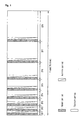
- Fig. 1 is a view illustrating a method for embodying the image in the conventional plasma display apparatus.
- one frame period is divided into a plurality of subfields (the frequency of discharge in each subfield differs from those in the others), the plasma display panel emits the light in the subfield period corresponding to a gray level value of an image signal to be input, and so the image is embodied.
- Each subfield is divided into a reset period for exciting uniformly the discharge, an address period for selecting the discharge cell and a sustain period for embodying the gray level according to the frequency of discharge. For example, in the case that the image with 256 gray levels is displayed, the frame period (16.67 ms) corresponding to 1/60 second is divided into eight subfields.
- each of eight subfields is divided into the reset period, the address period and the sustain period again.
- Fig. 2 is a graph for comparing the luminance characteristic of the plasma display apparatus with the luminance characteristic of the cathode ray tube.
- the light to be displayed according to the input video signal is controlled in an the analog manner to represent the desired gray level, and so the cathode ray tube and the liquid crystal display device generally indicate a non-linear luminance characteristic.
- the number of the light pulse is modulated by using a matrix array of the discharge cells which can be turned on/off to represent the gray level, and so and the plasma display indicates a linear luminance characteristic.
- Such method for representing the gray level of the plasma display apparatus is called as the PWM (pulse width modulation) method.
- the display apparatus such as the cathode ray tube sends the signal corresponding to a reciprocal of 2.2 multiplier of an external input image signal such as the broadcasting signal. Accordingly, there is a need to inverse gamma correct the external input image signal in the plasma display apparatus indicating a linear brightness characteristic.
- Fig. 3 is a graph showing an inverse gamma correction in the conventional plasma display apparatus.
- the target luminance indicates the ideal result to be obtained by the inverse gamma correction
- the real luminance indicates a measured luminance value represented as a result of the inverse gamma correction
- the PDP luminance indicates the luminance value of 3 or less which is measured in the state that the inverse gamma correction is not performed.
- the target luminance is represented as one of the luminance values, each of which has the gray level of 61 steps (0 through 60).
- the real luminance is represented as eight luminance values, each of which has one of the gray levels of 61 steps (0 through 60). Accordingly, when the inverse gamma correction process is performed in the plasma display apparatus, a sufficient gray level representation can not be obtained in a dark area, and so there is a problem that the contour noise in which the images are lumped together is appeared.
- a half tone method such as a dithering method and an error diffusion method and the like has been used.
- the dithering method is the method for judging whether a carry is generated or not by comparing the gray level value of each pixel with a specific threshold of a dither mask. That is, the dithering method is the method for enhancing the insufficient gray level capability by turning on the pixel in which the carry is generated and turning off the pixel in which the carry is not generated.
- Such dithering mask uses a plurality of dither masks on which constant patterns are formed. Accordingly, there is a problem that the patterns of the dither mask are displayed on a screen due to repeated use of the dither mask.
- the error diffusion method is used together with the dithering method as shown in Fig. 4.
- Fig. 4 is a view for illustrating the conventional method for using the error diffusion technique together with the dithering technique.
- a gray level data of the image signal which is already inverse gamma corrected is divided into an integer bit and a fraction bit first and the fraction bit is divided again into a superior bit and a subordinate bit. Then, the error diffusion is performed to the subordinate bit, if the carry is generated, the carry is reflected in the superior bit. Also, the dithering is performed to the superior bit, if the carry is generated, the carry is reflected in the integer bit.
- the integer bit is called as the real gray level
- the image of the plasma display apparatus is embodied finally by using the real gray level value, and so it is possible to represent the various gray levels.
- Fig. 5 is a view illustrating the problem occurred when the conventional method in which the error diffusion and the dithering are used together is applied.
- pixels of the error diffusion pattern in which carry is generated are matched with pixels of the A typed dithering mask pattern in which carry is generated, and so desired image is embodied, while the pixels of the error diffusion pattern in which carry is generated are not matched with pixels of the B typed dithering mask pattern in which carry is generated, and so desired image is not embodied at all.
- luminance differences of the screen on which the image is displayed are generated up to 50%. Due to such luminance differences, the flicker phenomenon in which the screen is flickered is occurred.
- dark marks in the error diffusion pattern and dithering mask pattern indicate locations of the pixels in which carry is generated
- dark marks in the screen on which the image is displayed indicate locations of the pixels which are turned on/off depending on whether carry is generated or not.
- each gray level of R (red), G (green) and B (blue) of the origin image signal is distorted, and so the color of the image to be embodied is changed.
- an object of the present invention is to solve at least the problems and disadvantages of the background art.
- An object of the present invention is to provide the plasma display apparatus and the image processing method thereof which can enhance the gray lever representation capability by improving a halftone section and a method thereof.
- Another object of the present invention is to provide the plasma display apparatus and the image processing method thereof which can prevent a flicker phenomenon from occurring in the case that the error diffusion method is applied together with the dithering method.
- a further another object of the present invention is to provide the plasma display apparatus and the image processing method thereof which can prevent the image to be embodied from distorting.
- the plasma display apparatus comprises a plasma display panel including a plurality of address electrodes; an inverse gamma correction section for inverse gamma-correcting an image signal inputted from an exterior; a halftone section for dividing a plurality of pixels adjacent to each other which a subordinate bit of a fraction bit of the image signal is allocated to into at least two or more types, performing an error diffusion among the subordinate bit of the fraction bit of the pixels corresponding to the same type, and performing a dithering of a superior bit of the fraction bit using at least two or more dither mask patterns; and a subfield mapping section for mapping the image signal which is halftone processed on the corresponding subfield.
- the method for processing an image in a plasma display apparatus comprises the steps of (a) inverse gamma-correcting an image signal inputted from an exterior; (b) dividing a plurality of pixels adjacent to each other which a subordinate bit of a fraction bit of the image signal is allocated to into at least two or more types, performing an error diffusion among the subordinate bit of the fraction bit of the pixels corresponding to the same type, and performing a dithering of a superior bit of the fraction bit using at least two or more dither mask patterns; and (c) mapping the image signal which is halftone processed on the corresponding subfield.
- the plasma display apparatus of the present invention is advantageous in that the gray lever representation capability can be enhanced by improving the halftone section and the method thereof.
- the present invention is advantageous in that it is possible to prevent a flicker phenomenon from occurring in the case that the error diffusion method is applied together with the dithering method.
- the present invention can prevent the image to be embodied from distorting.
- Fig. 1 is a view illustrating a method for embodying the image in the conventional plasma display apparatus
- Fig. 2 is a graph for comparing the luminance characteristic of the plasma display apparatus with the luminance characteristic of the cathode ray tube;
- Fig. 3 is a graph showing an inverse gamma correction in the conventional plasma display apparatus
- Fig. 4 is a view for illustrating the conventional method for using the error diffusion technique together with the dithering technique.
- Fig. 5 is a view illustrating the problem occurred when the conventional method in which the error diffusion and the dithering are used together is applied.
- Fig. 6 is a block diagram for illustrating the plasma display apparatus according to one embodiment of the present invention.
- Fig. 7 is a view for illustrating the error diffusion method according to one embodiment of the present invention.
- Fig. 8 is a view showing schematically that the error diffusion is performed on the entire screen by the error diffusion method according to one embodiment of the present invention.
- Fig. 9 is a view showing schematically a lookup table in which the error diffusion coefficient according to one embodiment of the present is stored.
- Fig. 10 is a view for illustrating the method according to one embodiment of the present in which the error diffusion is used together with the dithering.
- the plasma display apparatus comprises a plasma display panel including a plurality of address electrodes; an inverse gamma correction section for inverse gamma-correcting an image signal inputted from an exterior; a halftone section for dividing a plurality of pixels adjacent to each other which a subordinate bit of a fraction bit of the image signal is allocated to into at least two or more types, performing an error diffusion among the subordinate bit of the fraction bit of the pixels corresponding to the same type, and performing a dithering of a superior bit of the fraction bit using at least two or more dither mask patterns; and a subfield mapping section for mapping the image signal which is halftone processed on the corresponding subfield.
- the present invention is characterized in that at least two or more types are used in each frame in the regular order.
- the present invention is characterized in that at least two or more types are used in each frame in the random order.
- the present invention is characterized in that the number of the types is same as the number of the dither mask patterns.
- the present invention is characterized in that the type is selected according to the dither mask patterns.
- the present invention is characterized in that the pixels have the error diffusion directions which differ from each other according to the type.
- the present invention is characterized in that the pixels have the error diffusion directions which differ from each other in the line unit.
- the present invention is characterized in that a lookup table storage section which the error diffusion coefficient is stored in advance is further provided.
- the present invention is characterized in that the error diffusion coefficients which differ from each other are assigned according to the type.
- the present invention is characterized in that the error diffusion coefficient is decided according to a location of the pixel adjacent to a certain central pixel in any one type.
- the present invention is characterized in that the error diffusion coefficient is decided according to a gray level value of the subordinate bit.
- a method for processing an image in a plasma display apparatus comprises the steps of (a) inverse gamma-correcting an image signal inputted from an exterior; (b) dividing a plurality of pixels adjacent to each other which a subordinate bit of a fraction bit of the image signal is allocated to into at least two or more types, performing an error diffusion among the subordinate bit of the fraction bit of the pixels corresponding to the same type, and performing a dithering of a superior bit of the fraction bit using at least two or more dither mask patterns; and (c) mapping the image signal which is halftone processed on the corresponding subfield.
- the present invention is characterized in that at least two or more types are used in each frame in the regular order.
- the present invention is characterized in that at least two or more types are used in each frame in the random order.
- the present invention is characterized in that the number of the types is same as the number of the dither mask patterns.
- the present invention is characterized in that the type is selected according to the dither mask patterns.
- the present invention is characterized in that the pixels have the error diffusion directions which differ from each other according to the type.
- the present invention is characterized in that the pixels have the error diffusion directions which differ from each other in the line unit.
- the present invention is characterized in that the step of storing the error diffusion coefficient in a lookup table in advance is further comprised.
- the present invention is characterized in that the error diffusion coefficients which differ from each other are assigned according to the type.
- the present invention is characterized in that the error diffusion coefficient is decided according to a location of the pixel adjacent to a certain central pixel in any one type.
- the present invention is characterized in that the error diffusion coefficient is decided according to a gray level value of the subordinate bit.
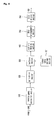
- Fig. 6 is a block diagram for illustrating the plasma display apparatus according to one embodiment of the present invention.
- the plasma display apparatus is provided with an inverse gamma correction section 610, a gain control section 620, a halftone section 630, a subfield mapping section 640, a data arrangement section 650 and a data driving section 660.
- the inverse gamma correction section 610 inverse gamma-corrects an image signal to be inputted to convert linearly a luminance value displayed according to the gray level value of the input image signal.
- the gain control section 620 multiplies the image signal of R (red), G (green) and B (blue) which is inverse gamma-corrected by the inverse gamma correction section 610 by a gain value which can be adjusted by an user or a set maker to adjust separately the gain of the image signals of R (red), G (green) and B (blue). At this time, the user or the set maker sets a color temperature to a desired value through the gain control section 620.
- the halftone section 630 halftone-processes the image signal inputted from the gain control section 620, and so the luminance value displayed according to the gray level value is finely adjusted to enhance the gray level representation capability.
- the subordinate bit of the fraction bit of the image signal which is inverse gamma-corrected divides a plurality of pixels into at least two or more types, the error diffusion is performed among the pixels corresponding to any one type, a carry generated through the error diffusion is reflected in the superior bit of the fraction bit.
- the superior bit reflecting the carry performs a dithering using at least two or more dither mask patterns, a carry generated through the dithering is reflected in an integer bit.
- the error diffusion coefficients which differ from each other according to the error diffusion type are assigned and, in any one type, the error diffusion coefficient is decided according to a location of pixel adjacent a specific pixel as a center pixel and the gray level value of the center pixel.
- the error diffusion is performed in real time when the plasma display apparatus is operated. That is, the halftone section 630 receives the error diffusion coefficient information from lookup table storage section 631 and performs the error diffusion.
- the error diffusion coefficient lookup table storage section 631 is provided inside or outside of the halftone section 630.
- the halftone section 630 uses at least two or more types in each frame in the regular order or uses at least two or more types in each frame in random order.
- the halftone section 630 selects and uses any one type according to the dither mask pattern.
- the number of the type is same as the number of the dither mask pattern.
- the halftone section 630 has different diffusion directions according to the error diffusion type or a pixel line of the plasma display panel. A detailed description on the operation characteristic of the halftone section 630 will be described below.
- the subfield mapping section 640 maps the image signal inputted from the halftone section 630 in a subfield mapping table which is set in advance.
- the data arrangement section 650 arranges the subfield mapping data which is inputted from the subfield mapping section 640 and arranged spatially into the data relating to the time.
- the data driving section 660 receives the data relating to the time arranged by the data arrangement section 650 and supplies an address electrode (not shown) of the plasma display panel with the address driving pulse, and so the image of the plasma display panel is embodied.
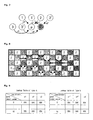
- Fig. 7 is a view for illustrating the error diffusion method according to one embodiment of the present invention.
- the pixels in which carry are generated are not matched with each other according to the pixels, as shown in Fig. 7, in the error diffusion method according to one embodiment of the present invention, a plurality of pixels adjacent to each other are divided into at least two or more types and the error diffusion is performed between the pixels corresponding to any one type in each frame.
- a pixel P and a pixel P' are set as a central pixel, respectively, and a plurality of pixels is divided into the A type pixels with the central pixel P as the center and the B type pixels with the central pixel P as the center.
- the central pixels are the pixel to which the error diffusion of the adjacent pixels is transmitted.
- the error diffusion is performed by means of the A type pixels.
- the subordinate bit of the fraction bit assigned to the pixel 1 is multiplied by the error diffusion coefficient c1
- the subordinate bit of the fraction bit assigned to the pixel 2 is multiplied by the error diffusion coefficient c2
- the subordinate bit of the fraction bit assigned to the pixel 3 is multiplied by the error diffusion coefficient c3.
- the error component diffused to the central pixel P is calculated by adding the values obtained by multiplying the subordinate bits of the pixels 1, 2 and 3 by the error diffusion coefficients c1, c2 and c3, respectively.
- the error component is the value obtained by multiplying the subordinate bit by the error diffusion coefficient and then diffused to the central pixel.
- the subordinate bit is reflected in the superior bit of the fraction bit depending on whether carry is generated or not.
- the error diffusion of the changed subordinate bit of the pixel P is performed again for to the A typed adjacent pixel.
- the error diffusion is performed by means of the A' type pixels.
- the subordinate bit of the fraction bit assigned to the pixel 1' is multiplied by the error diffusion coefficient c1'
- the subordinate bit of the fraction bit assigned to the pixel 2' is multiplied by the error diffusion coefficient c2'
- the subordinate bit of the fraction bit assigned to the pixel 3' is multiplied by the error diffusion coefficient c3'.
- the error component diffused to the central pixel P' is calculated by adding the values obtained by multiplying the subordinate bits of the pixels 1', 2' and 3' by the error diffusion coefficients c1', c2' and c3', respectively.
- the error component is the value obtained by multiplying the subordinate bit by the error diffusion coefficient and then diffused to the central pixel.
- the subordinate bit is reflected in the superior bit of the fraction bit depending on whether carry is generated or not.
- the error diffusion of the changed subordinate bit of the pixel P' is performed again for to the A' typed adjacent pixel.
- the A type pixel and the A' type pixel have not influence on each other.
- the each frame has the error diffusion pattern aspect which differs from those of the frames in the entire screen.
- the various type pixels according to one embodiment of the present invention are used in each frame in the regular order.
- the error diffusion is performed evenly for the entire pixels.
- the various type pixels according to another embodiment of the present invention are used in each frame in the random order.
- the plurality types of the pixels in each frame in the random order it is possible to prevent the error diffusion pattern from occurring regularly on the embodied image.
- Fig. 8 is a view showing schematically that the error diffusion is performed on the entire screen by the error diffusion method according to one embodiment of the present invention.
- the pixels on the entire screen are divided into the pixels indicated by 1 and the pixels indicated by 2 and the error diffusion is performed for the pixels. That is, the error diffusion is performed among the pixels indicated by 1 in the N th frame, and the error diffusion is performed among the pixels indicated by 2 in the N + 1 th frame.
- the entire pixels have same error diffusion directions, and the error diffusion patterns having the constant directivity are generated on the embodied image.
- Such error diffusion patterns having the constant directivity act as a factor by which the matching is impeded, taking the above fact into consideration, the error diffusions are not performed in the constant direction during one frame in one embodiment of the present invention.
- the unit lines have the error diffusion directions which differ from each other.
- the error diffusion is performed among the pixels selected during one frame, the error diffusion in one line is performed from the left pixel to the right pixel with respect to a horizontal direction of the screen, and the error diffusion in another line is performed from the right pixel to the left pixel.
- the frames have the error diffusion directions which differ from each other according to the selected type.
- the error diffusion has the first directivity by which the error diffusion is performed from left side to right side as well as from upper side to lower side of the screen according to the selected type.
- the error diffusion has the second directivity by which the error diffusion is performed from left side to right side as well as from lower side to upper side of the screen according to the selected type.
- the error diffusion has the third directivity by which the error diffusion is performed from right side to left side as well as from upper side to lower side of the screen according to the selected type.
- the error diffusion has the fourth directivity by which the error diffusion is performed from right side to left side as well as from lower side to upper side of the screen according to the selected type.
- Fig. 9 is a view showing schematically a lookup table in which the error diffusion coefficient according to one embodiment of the present is stored.
- a plurality of lookup tables are provided, the error diffusion coefficients which differ from each other according to the type are assigned to the lookup tables.
- the purpose of providing the lookup tables is to optimize a matching degree of the selected error diffusion pattern and any one dither mask pattern according to the error diffusion pattern.
- the error diffusion coefficient refers to the weights in which the error component which is decided according to a location of each pixel adjacent to the central pixel is reflected.
- the error diffusion coefficient is not only decided according to a location of the pixel adjacent to the specific pixel, but also the error diffusion coefficient is decided according to the gray level value of the subordinate bit assigned to the pixel located at that position. That is, a formation of the error diffusion patterns which are displayed regularly can be suppressed by deciding the error diffusion coefficient according to a location and the gray level value of the adjacent pixel in the selected type.
- the error diffusion coefficient is decided according to a location and the gray level value of the adjacent pixel so that the fine and reliable matching is achieved when the error diffusion method and the dithering method are used together.
- two lookup tables are provided according to the A type pixels and the B type pixels of Fig. 7 and Fig. 8.
- Fig. 10 is a view for illustrating the method according to one embodiment of the present in which the error diffusion is used together with the dithering.
- the error diffusion pattern and dithering patterns in Fig. 10 indicate locations of the pixels in which carry is generated, the patterns of the displayed screen indicate locations of pixels which are turned actually on/off depending on whether the carry is generated or not.
- Fig. 10 (a) shows that the number of the error diffusion types is same as the number of the dither mask pattern matched with the error diffusion type, and any one error diffusion type which is matched optimally with the dither mask pattern is selected and used. With this, the matching problem generated in the conventional art can be solved. In addition, since the luminance is not changed rapidly, it is possible to prevent the flicker phenomenon from being generated, and the above method is applied to each of R, G, and B image signals, and so a distortion of the image is suppressed.
- Fig. 10 (b) shows that any one error diffusion type is selected from a plurality of the error diffusion types according to at least two or more dither mask patterns and used. That is, due to the error diffusion type, the error diffusion directivity and a characteristic of the error diffusion coefficient according to one embodiment of the present invention, the error diffusion pattern which is uniformly appeared is reduced. Due to a reduction of the constant error diffusion pattern, the problem that the carry is not matched, which is extremely appeared in a conventional apparatus, is solved. In one embodiment of the present invention, accordingly, it is possible to use one error diffusion type together with at least two or more dither mask patterns. Two frames shown in Fig. 10 are displayed with the same luminance value. With this, the flicker phenomenon is prevented and a distortion of the image is suppressed, and so the gray level representation capability of the displayed image is enhance.
Landscapes
- Engineering & Computer Science (AREA)
- Physics & Mathematics (AREA)
- Computer Hardware Design (AREA)
- General Physics & Mathematics (AREA)
- Theoretical Computer Science (AREA)
- Plasma & Fusion (AREA)
- Power Engineering (AREA)
- Control Of Indicators Other Than Cathode Ray Tubes (AREA)
- Control Of Gas Discharge Display Tubes (AREA)
- Transforming Electric Information Into Light Information (AREA)
Applications Claiming Priority (1)
| Application Number | Priority Date | Filing Date | Title |
|---|---|---|---|
| KR1020040053488A KR100625464B1 (ko) | 2004-07-09 | 2004-07-09 | 플라즈마 디스플레이 패널의 화상처리 방법 |
Publications (2)
| Publication Number | Publication Date |
|---|---|
| EP1615199A2 true EP1615199A2 (de) | 2006-01-11 |
| EP1615199A3 EP1615199A3 (de) | 2007-08-01 |
Family
ID=35134636
Family Applications (1)
| Application Number | Title | Priority Date | Filing Date |
|---|---|---|---|
| EP05014651A Withdrawn EP1615199A3 (de) | 2004-07-09 | 2005-07-06 | Plasmaanzeigegerät und Bildverarbeitungsverfahren dafür |
Country Status (5)
| Country | Link |
|---|---|
| US (1) | US7649510B2 (de) |
| EP (1) | EP1615199A3 (de) |
| JP (1) | JP4192168B2 (de) |
| KR (1) | KR100625464B1 (de) |
| CN (1) | CN1719499A (de) |
Families Citing this family (11)
| Publication number | Priority date | Publication date | Assignee | Title |
|---|---|---|---|---|
| EP1821275A1 (de) * | 2006-02-20 | 2007-08-22 | Deutsche Thomson-Brandt Gmbh | Verfahren und Vorrichtung zur Ansteuerung einer Plasmaanzeigetafel mit Dämpfungsschätzung und Kompensierung. |
| US20100033509A1 (en) * | 2007-03-01 | 2010-02-11 | Panasonic Corporation | Image display device |
| KR100855988B1 (ko) * | 2007-03-13 | 2008-09-02 | 삼성전자주식회사 | 랜덤한 시/공간적 디더링 처리 방법 및 장치와 이를 이용한액정 표시 장치 |
| KR20090011071A (ko) * | 2007-07-25 | 2009-02-02 | 삼성전자주식회사 | 디스플레이장치 및 그 제어방법 |
| JP4549418B2 (ja) * | 2008-03-04 | 2010-09-22 | シャープ株式会社 | 画像処理装置、画像処理方法、画像形成装置、並びに、プログラム、記録媒体 |
| WO2010014359A2 (en) * | 2008-08-01 | 2010-02-04 | Sipix Imaging, Inc. | Gamma adjustment with error diffusion for electrophoretic displays |
| KR100970883B1 (ko) * | 2008-10-08 | 2010-07-20 | 한국과학기술원 | 영역 특성을 고려한 영상 보정 장치 및 그 방법 |
| JP5750969B2 (ja) * | 2011-03-24 | 2015-07-22 | セイコーエプソン株式会社 | 画像処理装置、印刷装置、画像処理方法および画像処理プログラム |
| JP6755773B2 (ja) * | 2016-10-28 | 2020-09-16 | 株式会社Joled | 表示装置、表示装置の補正方法、表示装置の製造方法、および表示装置の表示方法 |
| CN106878440B (zh) * | 2017-02-27 | 2019-08-06 | 多林科技(武汉)有限公司 | 正向编址和反向重编址互联通信方法、设备和系统 |
| CN110365865B (zh) * | 2018-03-26 | 2021-07-20 | 奇景光电股份有限公司 | 影像处理装置 |
Family Cites Families (22)
| Publication number | Priority date | Publication date | Assignee | Title |
|---|---|---|---|---|
| US5313287A (en) * | 1993-04-30 | 1994-05-17 | Hewlett-Packard Company | Imposed weight matrix error diffusion halftoning of image data |
| JP3354741B2 (ja) * | 1995-04-17 | 2002-12-09 | 富士通株式会社 | 中間調表示方法及び中間調表示装置 |
| JPH0962250A (ja) * | 1995-06-12 | 1997-03-07 | Ricoh Co Ltd | 画像加工装置および画像加工方法 |
| US6614413B2 (en) * | 1998-04-22 | 2003-09-02 | Pioneer Electronic Corporation | Method of driving plasma display panel |
| JP3789052B2 (ja) | 1998-12-03 | 2006-06-21 | パイオニア株式会社 | プラズマディスプレイパネルの駆動方法 |
| JP3540683B2 (ja) | 1998-09-22 | 2004-07-07 | 松下電器産業株式会社 | 多階調画像表示方法 |
| JP3460601B2 (ja) | 1998-11-26 | 2003-10-27 | 日本ビクター株式会社 | マトリクス型表示装置の映像信号処理回路及び映像信号処理方法 |
| JP3250995B2 (ja) | 1999-01-22 | 2002-01-28 | 松下電器産業株式会社 | 表示装置及び方法 |
| WO2000043979A1 (en) * | 1999-01-22 | 2000-07-27 | Matsushita Electric Industrial Co., Ltd. | Apparatus and method for making a gray scale display with subframes |
| US6606168B1 (en) * | 1999-03-31 | 2003-08-12 | 3M Innovative Properties Company | Narrow band, anisotropic stochastic halftone patterns and methods of creating and using the same |
| US6965389B1 (en) * | 1999-09-08 | 2005-11-15 | Victor Company Of Japan, Ltd. | Image displaying with multi-gradation processing |
| JP3961171B2 (ja) | 1999-11-24 | 2007-08-22 | パイオニア株式会社 | ディスプレイ装置の多階調処理回路 |
| JP3767791B2 (ja) * | 2000-04-18 | 2006-04-19 | パイオニア株式会社 | ディスプレイパネルの駆動方法 |
| JP2003533715A (ja) * | 2000-05-09 | 2003-11-11 | コーニンクレッカ フィリップス エレクトロニクス エヌ ヴィ | 画像をサブフィールドで表示する方法及びユニット |
| EP1316083A1 (de) * | 2000-08-30 | 2003-06-04 | Koninklijke Philips Electronics N.V. | Matrixanzeigegerät mit gleichzeitiger adressierung von mehreren linien |
| JP2002351389A (ja) * | 2001-05-24 | 2002-12-06 | Pioneer Electronic Corp | 表示装置及び方法 |
| JP2003015588A (ja) * | 2001-06-28 | 2003-01-17 | Pioneer Electronic Corp | ディスプレイ装置 |
| KR100420789B1 (ko) * | 2001-07-11 | 2004-03-02 | 학교법인 인하학원 | 플라즈마 디스플레이(pdp)에서의 계조 표현을 위한디더링 방법 및 그 시스템 |
| JP4034562B2 (ja) | 2001-12-20 | 2008-01-16 | エルジー エレクトロニクス インコーポレイティド | 表示装置及び階調表示方法 |
| JP4170713B2 (ja) * | 2002-09-13 | 2008-10-22 | パイオニア株式会社 | 表示パネルの駆動方法 |
| JP4410997B2 (ja) * | 2003-02-20 | 2010-02-10 | パナソニック株式会社 | 表示パネルの駆動装置 |
| KR20050077132A (ko) * | 2004-01-26 | 2005-08-01 | 엘지전자 주식회사 | 플라즈마 디스플레이 패널의 구동 방법 |
-
2004
- 2004-07-09 KR KR1020040053488A patent/KR100625464B1/ko not_active Expired - Fee Related
-
2005
- 2005-07-06 EP EP05014651A patent/EP1615199A3/de not_active Withdrawn
- 2005-07-08 JP JP2005200910A patent/JP4192168B2/ja not_active Expired - Fee Related
- 2005-07-08 US US11/176,236 patent/US7649510B2/en not_active Expired - Fee Related
- 2005-07-11 CN CNA2005100828889A patent/CN1719499A/zh active Pending
Also Published As
| Publication number | Publication date |
|---|---|
| KR20060004392A (ko) | 2006-01-12 |
| US20060007067A1 (en) | 2006-01-12 |
| EP1615199A3 (de) | 2007-08-01 |
| JP4192168B2 (ja) | 2008-12-03 |
| US7649510B2 (en) | 2010-01-19 |
| CN1719499A (zh) | 2006-01-11 |
| JP2006023754A (ja) | 2006-01-26 |
| KR100625464B1 (ko) | 2006-09-20 |
Similar Documents
| Publication | Publication Date | Title |
|---|---|---|
| US7649510B2 (en) | Plasma display apparatus and image processing method thereof | |
| US7414598B2 (en) | Apparatus and method for driving plasma display panel | |
| KR20030067930A (ko) | 플라즈마 디스플레이 패널의 화이트 밸런스 보상방법 및장치 | |
| US7515119B2 (en) | Method and apparatus for calculating an average picture level and plasma display using the same | |
| KR100646293B1 (ko) | 플라즈마 디스플레이 패널의 화상처리 방법 | |
| US7609283B2 (en) | Plasma display apparatus and image processing method thereof | |
| KR20050076442A (ko) | 플라즈마 디스플레이 패널의 화상처리 방법 | |
| KR100738816B1 (ko) | 플라즈마 디스플레이 패널의 화상처리 장치 및 화상처리방법 | |
| KR100705841B1 (ko) | 플라즈마 디스플레이 장치 및 그 화상처리 방법 | |
| KR101046972B1 (ko) | 플라즈마 디스플레이 패널의 화상처리 방법 | |
| KR20060104234A (ko) | 플라즈마 디스플레이 패널의 화상처리 장치 및 화상처리방법 | |
| KR100625476B1 (ko) | 플라즈마 디스플레이 장치 및 그 화상처리 방법 | |
| KR100658353B1 (ko) | 플라즈마 디스플레이 패널의 화상처리 장치 및 화상처리방법 | |
| KR100612516B1 (ko) | 플라즈마 디스플레이 패널의 화상처리 장치 및 화상처리방법 | |
| KR20050101442A (ko) | 플라즈마 디스플레이 패널의 화상 처리 장치 | |
| WO2005057540A1 (en) | Method and apparatus of processing video data for plasma display panel | |
| KR100625478B1 (ko) | 플라즈마 디스플레이 장치 및 그 화상처리 방법 | |
| KR100579933B1 (ko) | 플라즈마 디스플레이 패널의 화상처리 장치 및 화상처리방법 | |
| KR100612514B1 (ko) | 플라즈마 디스플레이 패널의 화상처리 장치 및 화상처리방법 | |
| KR100658359B1 (ko) | 플라즈마 디스플레이 패널의 화상처리 장치 및 화상처리 방법 | |
| KR100625549B1 (ko) | 플라즈마 디스플레이 패널의 화상처리 방법 | |
| KR100612517B1 (ko) | 플라즈마 디스플레이 패널의 화상처리 장치 및 화상처리방법 | |
| KR100757544B1 (ko) | 플라즈마 디스플레이 패널의 화상처리 장치 및 화상처리방법 | |
| KR100649532B1 (ko) | 플라즈마 표시 장치 및 그 구동 방법 | |
| KR20060083041A (ko) | 플라즈마 디스플레이 패널 구동 장치 및 방법 |
Legal Events
| Date | Code | Title | Description |
|---|---|---|---|
| PUAI | Public reference made under article 153(3) epc to a published international application that has entered the european phase |
Free format text: ORIGINAL CODE: 0009012 |
|
| 17P | Request for examination filed |
Effective date: 20050706 |
|
| AK | Designated contracting states |
Kind code of ref document: A2 Designated state(s): AT BE BG CH CY CZ DE DK EE ES FI FR GB GR HU IE IS IT LI LT LU LV MC NL PL PT RO SE SI SK TR |
|
| AX | Request for extension of the european patent |
Extension state: AL BA HR MK YU |
|
| PUAL | Search report despatched |
Free format text: ORIGINAL CODE: 0009013 |
|
| AK | Designated contracting states |
Kind code of ref document: A3 Designated state(s): AT BE BG CH CY CZ DE DK EE ES FI FR GB GR HU IE IS IT LI LT LU LV MC NL PL PT RO SE SI SK TR |
|
| AX | Request for extension of the european patent |
Extension state: AL BA HR MK YU |
|
| 17Q | First examination report despatched |
Effective date: 20080313 |
|
| AKX | Designation fees paid |
Designated state(s): DE FR GB NL |
|
| STAA | Information on the status of an ep patent application or granted ep patent |
Free format text: STATUS: THE APPLICATION IS DEEMED TO BE WITHDRAWN |
|
| 18D | Application deemed to be withdrawn |
Effective date: 20100202 |