EP1615528B2 - Element de liaison et systeme de bati - Google Patents
Element de liaison et systeme de bati Download PDFInfo
- Publication number
- EP1615528B2 EP1615528B2 EP04728311.4A EP04728311A EP1615528B2 EP 1615528 B2 EP1615528 B2 EP 1615528B2 EP 04728311 A EP04728311 A EP 04728311A EP 1615528 B2 EP1615528 B2 EP 1615528B2
- Authority
- EP
- European Patent Office
- Prior art keywords
- coupling
- struts
- connecting element
- strut
- elements
- Prior art date
- Legal status (The legal status is an assumption and is not a legal conclusion. Google has not performed a legal analysis and makes no representation as to the accuracy of the status listed.)
- Expired - Lifetime
Links
- 230000008878 coupling Effects 0.000 claims description 49
- 238000010168 coupling process Methods 0.000 claims description 49
- 238000005859 coupling reaction Methods 0.000 claims description 49
- 238000010276 construction Methods 0.000 claims description 2
- 230000002093 peripheral effect Effects 0.000 claims 1
- 238000003780 insertion Methods 0.000 description 3
- 230000037431 insertion Effects 0.000 description 3
- 238000005266 casting Methods 0.000 description 2
- 238000005192 partition Methods 0.000 description 2
- 125000006850 spacer group Chemical group 0.000 description 2
- 238000005452 bending Methods 0.000 description 1
- 230000015572 biosynthetic process Effects 0.000 description 1
- 230000007423 decrease Effects 0.000 description 1
- 230000003247 decreasing effect Effects 0.000 description 1
- 230000001419 dependent effect Effects 0.000 description 1
- 239000011521 glass Substances 0.000 description 1
- 238000004519 manufacturing process Methods 0.000 description 1
- 238000000465 moulding Methods 0.000 description 1
- 210000002105 tongue Anatomy 0.000 description 1
- 230000007704 transition Effects 0.000 description 1
Images


Classifications
-
- A—HUMAN NECESSITIES
- A47—FURNITURE; DOMESTIC ARTICLES OR APPLIANCES; COFFEE MILLS; SPICE MILLS; SUCTION CLEANERS IN GENERAL
- A47B—TABLES; DESKS; OFFICE FURNITURE; CABINETS; DRAWERS; GENERAL DETAILS OF FURNITURE
- A47B47/00—Cabinets, racks or shelf units, characterised by features related to dismountability or building-up from elements
- A47B47/0008—Three-dimensional corner connectors, the legs thereof being received within hollow, elongated frame members
-
- A—HUMAN NECESSITIES
- A47—FURNITURE; DOMESTIC ARTICLES OR APPLIANCES; COFFEE MILLS; SPICE MILLS; SUCTION CLEANERS IN GENERAL
- A47B—TABLES; DESKS; OFFICE FURNITURE; CABINETS; DRAWERS; GENERAL DETAILS OF FURNITURE
- A47B87/00—Sectional furniture, i.e. combinations of complete furniture units, e.g. assemblies of furniture units of the same kind such as linkable cabinets, tables, racks or shelf units
- A47B87/02—Sectional furniture, i.e. combinations of complete furniture units, e.g. assemblies of furniture units of the same kind such as linkable cabinets, tables, racks or shelf units stackable ; stackable and linkable
- A47B87/0207—Stackable racks, trays or shelf units
- A47B87/0223—Shelves stackable by means of poles or tubular members as distance-holders therebetween
-
- F—MECHANICAL ENGINEERING; LIGHTING; HEATING; WEAPONS; BLASTING
- F16—ENGINEERING ELEMENTS AND UNITS; GENERAL MEASURES FOR PRODUCING AND MAINTAINING EFFECTIVE FUNCTIONING OF MACHINES OR INSTALLATIONS; THERMAL INSULATION IN GENERAL
- F16B—DEVICES FOR FASTENING OR SECURING CONSTRUCTIONAL ELEMENTS OR MACHINE PARTS TOGETHER, e.g. NAILS, BOLTS, CIRCLIPS, CLAMPS, CLIPS OR WEDGES; JOINTS OR JOINTING
- F16B12/00—Jointing of furniture or the like, e.g. hidden from exterior
- F16B12/40—Joints for furniture tubing
Definitions
- the invention relates to the field of demountable frame structures for furniture construction, in particular to a connecting element and a rack system according to the preamble of claims 1 and 9.
- fasteners and frame systems based thereon are made EP 0 400 345 B1 and the writings cited therein.
- Wedges or wedge-shaped sleeves are used in rohrfömigen struts. These are pulled against each other by means of a clamping screw, wedged with the struts and thereby generate a positive connection with a corner joint.
- the fasteners are usually complicated to manufacture, have a lot of loose items and often require special assembly tools,
- GB 1,011,688 discloses a connecting element which has a plurality of outgoing from a central element coupling elements for connection to tubular struts.
- the Kupplungslemente have a rotationally cylindrical basic shape with at least one coupling recess, wherein a coupling recess is formed by two substantially perpendicular to an axis of the cylinder transverse grooves, and by a longitudinal groove which is parallel to the axis of the cylinder from an end side of the coupling element by a first transverse groove leads to a second transverse groove.
- the struts have inwardly projecting bulges, which engage in the insertion of the struts on the coupling elements in the longitudinal grooves. After complete insertion of the struts, the struts are rotated, the bulges engage in the transverse grooves, thus preventing stripping of the struts.
- US 6,260,488 B1 shows a shelving system
- the perpendicular columns can be connected in each case by a connecting element with another support and extended so.
- a connecting element When attaching a support to a connecting element engages here also a bulge in a longitudinal groove of the connecting element and can turn after the complete plugging into a transverse section of the groove.
- this transverse portion may have a cam (70), so that when turning the support engages the bulge on the cam.
- the transverse portion of the groove may have a decreasing depth, so that upon rotation of the support, the protrusions are pressed against the bottom of the groove and a clamping action occurs.
- US 3,765,541 shows a rack system in which vertical struts are interconnected by threaded rods, the threaded rods by spacers ("spacer members") and lead through connecting plates.
- the connecting plates are used to connect horizontal struts.
- a connecting element thus has Kupplungslemente, which have a rotationally cylindrical basic shape with at least one coupling recess.
- a coupling recess is formed by a transverse groove extending substantially perpendicular to an axis of the cylinder and by a longitudinal groove leading parallel to the axis of the cylinder from an end face of the coupling element to the transverse groove.
- the inventive connecting element allows to easily connect to a correspondingly formed strut of a frame, without any additional parts such as wedges, screws, etc. are required. Also, no threads need to be cut into the connector. Likewise, no tools are needed to make or break a connection.
- a strut is pushed over the Kupplungslement, wherein at least one inwardly facing locking element of the strut is guided in the groove of the Kupplungslements.
- the coupling element After the coupling element reaches the position of the transverse groove, it is screwed by turning the strut about its axis in the transverse groove.
- the transverse groove and / or the coupling element are shaped such that they jam together when turning.
- the locking element engages behind a formation of the transverse groove which forms a latching element, a.
- the jamming is done, for example, by the fact that when turning the strut, an end face of the strut is pressed against a first surface of the transverse groove and a contact surface of the locking element is pressed against a second surface of the transverse groove, wherein the first and second surfaces of the transverse groove facing each other.
- the longitudinal groove and the transverse groove in the circumferential direction, respectively seen in the axial direction of the coupling element, arranged symmetrically to each other, that is, the strut is hineininpitbar after sliding along the longitudinal groove in both directions of rotation in the transverse groove.
- a connecting element generally has two to four coupling elements whose respective longitudinal axes lie in a common plane or shelf plane. If the angles of the coupling elements to one another are multiples of a right angle, then, together with corresponding struts, a plane of a rectangular shelf can be composed of them.
- coupling elements are connected by a central element with each other.
- the central element has a tube whose inner diameter corresponds to an outer diameter of a vertical strut. Approximately in the middle of the tube, this has a perforated plate or partition plate, which is perpendicular to the tube axis and has a hole in the middle. Second struts or vertical struts are arranged to connect shelving planes perpendicular to the shelving planes. They have at one end a matching through the hole external thread, and at another end a corresponding internal thread. Alternatively, the vertical struts have internal threads on both ends into which a threaded piece can be screwed. For mounting a plurality of frame levels, a first vertical strut is inserted into the tube of the central element and with the external thread respectively a screwed threaded piece through the hole and bolted to the internal thread of a second vertical strut.
- the central element can also be designed differently than tubular, but also with rotationally cylindrical recesses for receiving vertical struts. These rotary cylindrical recesses are preferably arranged with the same inner diameter and aligned with each other, and interconnected by a hole.
- the invention has been explained with reference to a horizontal and vertical alignment of frame members. But it can also be connected to each other vertical frame levels by means of the coupling elements, and these frame levels are in turn connected by means of horizontally extending "vertical struts".
- a rack system has the described connecting elements and struts.
- the struts for connection to a coupling element are formed either continuously or at least at the ends of tubular.
- the inner diameter of these tubular sections corresponds to the outer diameter of the coupling elements.
- the struts have at least one end in each case at least one locking element, which protrudes from the tube wall in the radial direction in the lumen, that is, in the cavity of the tube. Locking elements at both ends of a struts are aligned with each other, that is, they are the same orientation in the circumferential direction. When connecting with symmetrical connecting elements at both ends of a strut and the connecting elements are the same orientation.
- a casting mold for producing a connecting element according to the invention has two substantially mirror-symmetrical mold halves.
- a parting plane between the mold halves corresponds to a plane which is defined by the axes of the at least two coupling elements. Due to the advantageous design of the connecting elements, in particular the arrangement of the grooves and the design of the central element, no further moldings for producing the undercuts by the grooves are necessary.
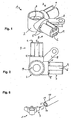
- Figures 1 and 2 show a connecting element 1 with two coupling elements 3 in a perspective view and a top view.
- the connecting element is a Eckitatis consortium 1 with a central element 2 and two coupling elements 3.
- a coupling element 3 has at least one coupling recess, which by a transverse groove 5 and one example rectangular longitudinal groove 6 is formed.
- a coupling element 3 preferably has a fully cylindrical part, ie a part without recesses. This has in cross section an outer boundary corresponding to a strut cross section.
- the fully cylindrical part is likewise rotationally cylindrical and has an outer diameter corresponding to that of a strut 10.
- the strut 10 side facing the fully cylindrical part forms a boundary of the transverse groove 5.
- the fully cylindrical part achieves a spacing of a first strut from the central element 2 and further optionally mounted on the central element 2 and at an angle to the first strut other struts , When turning the strut 10 during assembly, therefore, the central element 2 or other struts 10 are not scratched.
- the stability of the connecting element 1 is increased by the fully cylindrical parts.
- support arms 8 for attachment of, for example, plate-shaped monelbauianan, especially trays. These are provided for example for screw or for insertion of suction cups for holding glass plates.
- the support arms 8 are provided for placing the fused bit stream. They support the fused bit stream. They support the fused bit stream. They support the fused bit stream. They support the fused bit stream. They support the fused bit stream. They support the fused bit stream. It supports the a drill bit stream. They support the rod or for insertion of suction cups for holding glass plates.
- the support arms 8 are provided for placing the paperelbauemia. They support the fuse system so that the fiberelbaumaschinence without further fasteners in a mounted. Pipe system can be inserted.
- the support arms 8 are inserted into corners between the fully cylindrical parts, whereby a stable attachment of the support arms 8 can be achieved.
- FIGS. 3 and 4 show a connector 1 with three coupling elements 3 in a perspective view and a top view.
- the fully cylindrical part of a coupling element 3 extends from the transverse groove 5 to the central element 2.
- a diameter r1 of this fully cylindrical part is for example 19 mm, preferably at least approximately corresponding to an outer diameter of a strut 10.
- a length of the fully cylindrical part is for example one quarter of a strut diameter, or 2 mm to 10 mm.
- a diameter r2 of the coupling element 3 in the region between the transverse groove 5 and the end face of the coupling element 3 is for example 16.5 mm, corresponding to an inner diameter of a strut 10.
- the central element 2 is formed by a tube for receiving a vertical strut 14.
- the tube has in the axial direction approximately in the middle of a perpendicular to the tube axis arranged perforated plate or partition plate 9. This has a hole in the middle.
- a vertical strut 14 has either an outer diameter corresponding to the inner diameter of the central element 2 over the entire length, or an outer diameter equal to the outer diameter of the central element 2 and a pin fitting into the central element 2.
- FIG. 5 shows a perspective view of a corner connector 1 and a strut 10.
- a rectilinear movement for attaching the strut 10 to a coupling element 3 and a subsequent rotation is displayed for locking.
- Two locking elements 11 are arranged at the outermost end of the strut 10. A boundary surface of the locking elements 11 thus coincides at least approximately with an end boundary surface of the strut 10.
- the locking elements 11 extend from the tube circumference in the radial direction to the tube axis of the strut 10 back.
- a width of the transverse groove starting from a transition to the longitudinal groove in both directions perpendicular to the cylinder axis starting in the axial direction, that is parallel to the cylinder axis, is greater than at a from the longitudinal groove remote location.
- the transverse groove has a substantially planar surface, at least on the periphery, against which the strut 10 is pressed.
- the width of the transverse groove 5, starting from the longitudinal groove 6, first decreases, then closes, and then again. This creates a latching element 7, which causes a locking of the locking element 11 during rotation and prevents unintentional release of the strut 10.
- FIG. 6 shows a perspective view of a frame with detail views of connections of vertical struts.
- two-armed corner joints are used, at the locations marked B three-armed corner joints.
- Overlying horizontal planes of the frame are connected by vertical struts 14.
- the vertical struts 14 each have at both ends a concentric and projecting into the strut internal thread.
- a threaded piece 15 which fits into the internal thread can be guided through the opening of the perforated plate 9 of a central element and connects two vertical struts 14 arranged one above the other.
- covers 12, for example made of plastic are inserted into the central elements 2.
- feet 13 are screwed with the same threads as the vertical struts 14 in the respective central elements 2 and the overlying vertical struts 14.
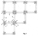
- FIG. 7 shows a plan view of a frame formed using fasteners with two, three and four coupling elements.
- the Ecktells publishede 1 can be produced in one piece by casting, with only two substantially identical mold halves are required due to the advantageous shape. All undercuts through the grooves can be easily created.
- the locking elements 11 are, for example, substantially rectangular or semicircular tongues, which are welded into the struts, or soldered. Alternatively, they can also be created by bending a protruding part of the strut.
Landscapes
- Engineering & Computer Science (AREA)
- General Engineering & Computer Science (AREA)
- Mechanical Engineering (AREA)
- Mutual Connection Of Rods And Tubes (AREA)
- Furniture Connections (AREA)
- Assembled Shelves (AREA)
Claims (10)
- Elément de liaison (1) destiné à relier des entretoises (10) d'un bâti de type meuble,
l'élément de liaison présentant deux à quatre éléments d'accouplement (3) destinés à être reliés à des entretoises tubulaires (10), partant d'un élément central (2) et dont tous les axes longitudinaux sont situés dans un plan commun,
les éléments d'accouplement (3) présentant une forme de base en cylindre de rotation dotée d'au moins une découpe d'accouplement,
une découpe d'accouplement étant formée par une rainure transversale (5) qui s'étend essentiellement à la perpendiculaire de l'axe du cylindre de la forme de base en cylindre de rotation de l'élément d'accouplement (3) et par une rainure longitudinale (6) parallèle à l'axe du cylindre et conduisant d'un côté frontal (4) de l'élément d'accouplement (3) à la rainure transversale (5),
caractérisé en ce que
l'élément central (2) présente un tube avec deux réservations cylindriques en rotation présentant le même diamètre intérieur, alignées l'une par rapport à l'autre et reliées l'une à l'autre par un trou au milieu d'une plaque perforée qui est située approximativement au milieu du tube et
en ce que l'axe des deux réservations cylindriques en rotation s'étend perpendiculairement aux axes des cylindres des différents éléments d'accouplement (3) et perpendiculairement à la plaque perforée. - Elément de liaison (1) selon la revendication 1, caractérisé en ce qu'un élément d'accouplement (3) présente une partie de cylindre plein dont la section transversale est limitée extérieurement en correspondance à la section transversale d'une entretoise et configurée pour maintenir une entretoise (10) montée à distance de l'élément central (2).
- Elément de liaison (1) selon les revendications 1 ou 2, caractérisé en ce que la rainure longitudinale (6) et la rainure transversale (5) sont disposées symétriquement l'une par rapport à l'autre dans la direction axiale de l'élément d'accouplement.
- Elément de liaison (1) selon l'une des revendications 1 à 3, caractérisé en ce que la largeur de la rainure transversale (5) partant de la rainure longitudinale (6) est plus grande dans la direction axiale qu'en un emplacement plus éloigné de la rainure longitudinale (6).
- Elément de liaison (1) selon la revendication 4, caractérisé en ce que la rainure transversale (5) présente un élément d'encliquetage (7).
- Elément de liaison (1) selon l'une des revendications 1 à 5, caractérisé en ce qu'il présente deux réservations d'accouplement qui sont disposées en opposition l'une à l'autre par rapport à l'axe du cylindre.
- Elément de liaison (1) selon l'une des revendications 1 à 6, caractérisé en ce que l'élément central (2) présente des bras de support (8) qui retiennent les éléments de montage de meuble et en particulier les retiennent en les soutenant.
- Système de bâti présentant des éléments de liaison (1) selon l'une des revendications 1 à 7 et des entretoises tubulaires (10), chacune des entretoises (10) présentant à au moins une extrémité un élément de verrouillage (11) qui, partant de la paroi du tube, pénètre dans la direction radiale dans la lumière du tube.
- Système de bâti selon la revendication 8, caractérisé en ce que les entretoises (10) présentent deux extrémités au moins un élément de verrouillage (11), ces éléments de verrouillage (11) présentant la même orientation dans la direction périphérique.
- Système de bâti selon les revendications 8 ou 9, caractérisé en ce qu'il présente des deuxièmes entretoises (14) qui présentent chacune à une extrémité un filet intérieur et à l'autre extrémité également un filet intérieur ou un filet extérieur correspondant.
Priority Applications (1)
| Application Number | Priority Date | Filing Date | Title |
|---|---|---|---|
| EP08015989A EP1995473A3 (fr) | 2003-04-22 | 2004-04-20 | Élément de liaison et système de râtelier |
Applications Claiming Priority (2)
| Application Number | Priority Date | Filing Date | Title |
|---|---|---|---|
| CH7122003 | 2003-04-22 | ||
| PCT/CH2004/000238 WO2004093603A1 (fr) | 2003-04-22 | 2004-04-20 | Element de liaison et systeme de bati |
Related Child Applications (2)
| Application Number | Title | Priority Date | Filing Date |
|---|---|---|---|
| EP08015989A Division-Into EP1995473A3 (fr) | 2003-04-22 | 2004-04-20 | Élément de liaison et système de râtelier |
| EP08015989A Division EP1995473A3 (fr) | 2003-04-22 | 2004-04-20 | Élément de liaison et système de râtelier |
Publications (3)
| Publication Number | Publication Date |
|---|---|
| EP1615528A1 EP1615528A1 (fr) | 2006-01-18 |
| EP1615528B1 EP1615528B1 (fr) | 2014-04-30 |
| EP1615528B2 true EP1615528B2 (fr) | 2018-02-21 |
Family
ID=33304422
Family Applications (2)
| Application Number | Title | Priority Date | Filing Date |
|---|---|---|---|
| EP04728311.4A Expired - Lifetime EP1615528B2 (fr) | 2003-04-22 | 2004-04-20 | Element de liaison et systeme de bati |
| EP08015989A Withdrawn EP1995473A3 (fr) | 2003-04-22 | 2004-04-20 | Élément de liaison et système de râtelier |
Family Applications After (1)
| Application Number | Title | Priority Date | Filing Date |
|---|---|---|---|
| EP08015989A Withdrawn EP1995473A3 (fr) | 2003-04-22 | 2004-04-20 | Élément de liaison et système de râtelier |
Country Status (3)
| Country | Link |
|---|---|
| EP (2) | EP1615528B2 (fr) |
| CN (2) | CN100581413C (fr) |
| WO (1) | WO2004093603A1 (fr) |
Families Citing this family (11)
| Publication number | Priority date | Publication date | Assignee | Title |
|---|---|---|---|---|
| WO2008064522A1 (fr) * | 2006-11-30 | 2008-06-05 | Fuzhuang Li | Structure de raccordement de tubes |
| USD762463S1 (en) | 2015-01-08 | 2016-08-02 | Clairson, Inc. | Bracket for a closet storage assembly |
| US9498058B2 (en) * | 2015-01-08 | 2016-11-22 | Clairson, Inc. | Closet storage assemblies, connectors, brackets and systems |
| DE102015009478B4 (de) | 2015-07-23 | 2017-10-12 | Peter Schnidtmann | Tragkonstruktion für ein zerlegbares Möbelstück |
| DE202015005221U1 (de) | 2015-07-23 | 2015-08-07 | Peter Schnidtmann | Tragkonstruktion für ein zerlegbares Möbelstück |
| CN105811175B (zh) * | 2016-04-13 | 2018-06-26 | 蔡海英 | 一种封杯机熔接杆连接器 |
| US10781838B2 (en) * | 2016-09-07 | 2020-09-22 | Lawrence V. Koepke | Connector device |
| CN107969813A (zh) * | 2017-10-13 | 2018-05-01 | 佛山市文杰影音设备有限公司 | 可扩展搁置架 |
| CN111012084B (zh) * | 2020-01-08 | 2025-07-22 | 广州南沙澳美发金属塑料制品有限公司 | 一种可叠放式自动找平支撑脚结构 |
| EP4477273A1 (fr) * | 2023-06-16 | 2024-12-18 | B/E Aerospace Systems GmbH | Cadre de support modulaire pour système d'alimentation en oxygène de secours d'aéronef, système d'alimentation en oxygène de secours d'aéronef et aéronef comprenant un système d'alimentation en oxygène de secours d'aéronef |
| CH722127B1 (de) | 2025-03-06 | 2026-03-31 | Duco System Ag | Modulares, mehrfach montierbares und demontierbares Gestellsystem |
Citations (1)
| Publication number | Priority date | Publication date | Assignee | Title |
|---|---|---|---|---|
| US5549408A (en) † | 1995-02-17 | 1996-08-27 | Lo; Wei W. | Connector for built-up toy furniture |
Family Cites Families (12)
| Publication number | Priority date | Publication date | Assignee | Title |
|---|---|---|---|---|
| US7318A (en) * | 1850-04-30 | Coupling foe pipes and hose | ||
| GB416217A (en) | 1933-07-26 | 1934-09-13 | Aufschwung Technik Und Handel | Method for the combination of rods, bars or tubes |
| US2839320A (en) * | 1954-12-07 | 1958-06-17 | Globe Company | Pipe connectors |
| GB1011688A (en) * | 1962-07-24 | 1965-12-01 | Witanda Engineering Ltd | A tube jointing device |
| US3765541A (en) * | 1971-04-07 | 1973-10-16 | Poster Products | Structural units and method of assembling them |
| US3883257A (en) * | 1973-11-05 | 1975-05-13 | Lane Company Inc | Molded joint component for tubular frame furniture |
| US4269532A (en) | 1979-07-10 | 1981-05-26 | Bright Industries Inc. | Coupling for furniture and the like |
| US4864795A (en) * | 1987-05-22 | 1989-09-12 | Uni Corp. | Structural framework system and clamp assembly |
| DE59002267D1 (de) | 1989-05-30 | 1993-09-16 | Schaerer Soehne Ag Usm U | Verbindungselement. |
| CN2090451U (zh) * | 1990-11-03 | 1991-12-11 | 泮良勇 | 组装家具的三向连接件 |
| US6260488B1 (en) * | 1999-07-06 | 2001-07-17 | Seville Classics, Inc. | Modular shelving |
| CN2484432Y (zh) * | 2001-05-31 | 2002-04-03 | 周木伟 | 支架连接件 |
-
2004
- 2004-04-20 WO PCT/CH2004/000238 patent/WO2004093603A1/fr not_active Ceased
- 2004-04-20 EP EP04728311.4A patent/EP1615528B2/fr not_active Expired - Lifetime
- 2004-04-20 EP EP08015989A patent/EP1995473A3/fr not_active Withdrawn
- 2004-04-20 CN CN200480010752A patent/CN100581413C/zh not_active Expired - Lifetime
- 2004-04-20 CN CN200910246171A patent/CN101816491A/zh active Pending
Patent Citations (1)
| Publication number | Priority date | Publication date | Assignee | Title |
|---|---|---|---|---|
| US5549408A (en) † | 1995-02-17 | 1996-08-27 | Lo; Wei W. | Connector for built-up toy furniture |
Also Published As
| Publication number | Publication date |
|---|---|
| CN101816491A (zh) | 2010-09-01 |
| EP1615528A1 (fr) | 2006-01-18 |
| CN100581413C (zh) | 2010-01-20 |
| EP1995473A3 (fr) | 2010-09-08 |
| EP1615528B1 (fr) | 2014-04-30 |
| HK1092339A1 (zh) | 2007-02-09 |
| CN1780573A (zh) | 2006-05-31 |
| WO2004093603A1 (fr) | 2004-11-04 |
| EP1995473A2 (fr) | 2008-11-26 |
Similar Documents
| Publication | Publication Date | Title |
|---|---|---|
| DE202017107404U1 (de) | Knotenverbinder für Profilsysteme oder dergleichen | |
| EP1615528B1 (fr) | Element de liaison et systeme de bati | |
| DE3443588C2 (de) | Anordnung zur Kreuzverbindung mindestens zweier Profile mit einem Knotenkörper | |
| EP0773615B1 (fr) | Armoire de commutation pour installation électrique | |
| EP0686363B1 (fr) | Construction de cadres avec plusieurs éléments de barres | |
| EP2348920B1 (fr) | Kit de construction | |
| DE2832087A1 (de) | Verbindung von hohlprofilen, insbesondere zum aufbau von regalen, geruesten u.dgl. | |
| EP0834974A2 (fr) | Baie pour une armoire de distribution électrique | |
| AT410121B (de) | Verbindungselement für rahmenprofile | |
| EP2245318B1 (fr) | Noeuds d' assemblage pour éléments profilés | |
| EP4114150A1 (fr) | Ensemble d'extension | |
| EP3406916B1 (fr) | Équerre pour profilés de support | |
| DE29912299U1 (de) | Regalsystem mit mindestens zwei miteinander verbindbaren Regalelementen | |
| DE2738321A1 (de) | Verbindungskupplung fuer rohrteile | |
| DE2612141A1 (de) | Verbindungs-beschlag | |
| DE4214520C2 (de) | Zapfenverbindung | |
| CH722127B1 (de) | Modulares, mehrfach montierbares und demontierbares Gestellsystem | |
| DE3328232A1 (de) | Raumfachwerk | |
| EP1275858B1 (fr) | Eléments de construction pour étagères | |
| EP4484768A1 (fr) | Dispositif de serrage pour la connexion démontable, de préférence bout à bout d'un premier profilé creux d'un cadre de meuble à un deuxième profilé creux du cadre de meuble ainsi que connexion bord à celui-ci | |
| WO2023209118A1 (fr) | Composant et élément de liaison pour système d'ameublement | |
| DE102022004709A1 (de) | Profilverbindungsanordnung und Ankerkörper | |
| DE202004003223U1 (de) | Eckverbinder | |
| EP3622854A1 (fr) | Meuble constitue d'une structure formée d'un cadre tubulaire assemblé par connecteurs | |
| DE29717184U1 (de) | Befestigungsvorrichtung |
Legal Events
| Date | Code | Title | Description |
|---|---|---|---|
| PUAI | Public reference made under article 153(3) epc to a published international application that has entered the european phase |
Free format text: ORIGINAL CODE: 0009012 |
|
| 17P | Request for examination filed |
Effective date: 20050929 |
|
| AK | Designated contracting states |
Kind code of ref document: A1 Designated state(s): AT BE BG CH CY CZ DE DK EE ES FI FR GB GR HU IE IT LI LU MC NL PL PT RO SE SI SK TR |
|
| AX | Request for extension of the european patent |
Extension state: AL HR LT LV MK |
|
| DAX | Request for extension of the european patent (deleted) | ||
| REG | Reference to a national code |
Ref country code: DE Ref legal event code: R079 Ref document number: 502004014601 Country of ref document: DE Free format text: PREVIOUS MAIN CLASS: A47B0047000000 Ipc: F16B0012400000 |
|
| RIC1 | Information provided on ipc code assigned before grant |
Ipc: A47B 87/02 20060101ALI20120912BHEP Ipc: A47B 47/00 20060101ALI20120912BHEP Ipc: F16B 12/40 20060101AFI20120912BHEP |
|
| GRAP | Despatch of communication of intention to grant a patent |
Free format text: ORIGINAL CODE: EPIDOSNIGR1 |
|
| INTG | Intention to grant announced |
Effective date: 20131112 |
|
| GRAS | Grant fee paid |
Free format text: ORIGINAL CODE: EPIDOSNIGR3 |
|
| GRAA | (expected) grant |
Free format text: ORIGINAL CODE: 0009210 |
|
| TPAC | Observations filed by third parties |
Free format text: ORIGINAL CODE: EPIDOSNTIPA |
|
| AK | Designated contracting states |
Kind code of ref document: B1 Designated state(s): AT BE BG CH CY CZ DE DK EE ES FI FR GB GR HU IE IT LI LU MC NL PL PT RO SE SI SK TR |
|
| REG | Reference to a national code |
Ref country code: GB Ref legal event code: FG4D Free format text: NOT ENGLISH Ref country code: CH Ref legal event code: EP |
|
| REG | Reference to a national code |
Ref country code: AT Ref legal event code: REF Ref document number: 665344 Country of ref document: AT Kind code of ref document: T Effective date: 20140515 |
|
| REG | Reference to a national code |
Ref country code: IE Ref legal event code: FG4D Free format text: LANGUAGE OF EP DOCUMENT: GERMAN |
|
| REG | Reference to a national code |
Ref country code: DE Ref legal event code: R096 Ref document number: 502004014601 Country of ref document: DE Effective date: 20140612 |
|
| RAP2 | Party data changed (patent owner data changed or rights of a patent transferred) |
Owner name: STRENG PLASTIC AG |
|
| REG | Reference to a national code |
Ref country code: NL Ref legal event code: VDEP Effective date: 20140430 |
|
| PG25 | Lapsed in a contracting state [announced via postgrant information from national office to epo] |
Ref country code: FI Free format text: LAPSE BECAUSE OF FAILURE TO SUBMIT A TRANSLATION OF THE DESCRIPTION OR TO PAY THE FEE WITHIN THE PRESCRIBED TIME-LIMIT Effective date: 20140430 Ref country code: BG Free format text: LAPSE BECAUSE OF FAILURE TO SUBMIT A TRANSLATION OF THE DESCRIPTION OR TO PAY THE FEE WITHIN THE PRESCRIBED TIME-LIMIT Effective date: 20140730 Ref country code: NL Free format text: LAPSE BECAUSE OF FAILURE TO SUBMIT A TRANSLATION OF THE DESCRIPTION OR TO PAY THE FEE WITHIN THE PRESCRIBED TIME-LIMIT Effective date: 20140430 Ref country code: GR Free format text: LAPSE BECAUSE OF FAILURE TO SUBMIT A TRANSLATION OF THE DESCRIPTION OR TO PAY THE FEE WITHIN THE PRESCRIBED TIME-LIMIT Effective date: 20140731 Ref country code: CY Free format text: LAPSE BECAUSE OF FAILURE TO SUBMIT A TRANSLATION OF THE DESCRIPTION OR TO PAY THE FEE WITHIN THE PRESCRIBED TIME-LIMIT Effective date: 20140430 |
|
| PG25 | Lapsed in a contracting state [announced via postgrant information from national office to epo] |
Ref country code: ES Free format text: LAPSE BECAUSE OF FAILURE TO SUBMIT A TRANSLATION OF THE DESCRIPTION OR TO PAY THE FEE WITHIN THE PRESCRIBED TIME-LIMIT Effective date: 20140430 Ref country code: PL Free format text: LAPSE BECAUSE OF FAILURE TO SUBMIT A TRANSLATION OF THE DESCRIPTION OR TO PAY THE FEE WITHIN THE PRESCRIBED TIME-LIMIT Effective date: 20140430 Ref country code: SE Free format text: LAPSE BECAUSE OF FAILURE TO SUBMIT A TRANSLATION OF THE DESCRIPTION OR TO PAY THE FEE WITHIN THE PRESCRIBED TIME-LIMIT Effective date: 20140430 |
|
| PG25 | Lapsed in a contracting state [announced via postgrant information from national office to epo] |
Ref country code: PT Free format text: LAPSE BECAUSE OF FAILURE TO SUBMIT A TRANSLATION OF THE DESCRIPTION OR TO PAY THE FEE WITHIN THE PRESCRIBED TIME-LIMIT Effective date: 20140901 |
|
| REG | Reference to a national code |
Ref country code: DE Ref legal event code: R026 Ref document number: 502004014601 Country of ref document: DE |
|
| PG25 | Lapsed in a contracting state [announced via postgrant information from national office to epo] |
Ref country code: RO Free format text: LAPSE BECAUSE OF FAILURE TO SUBMIT A TRANSLATION OF THE DESCRIPTION OR TO PAY THE FEE WITHIN THE PRESCRIBED TIME-LIMIT Effective date: 20140430 Ref country code: CZ Free format text: LAPSE BECAUSE OF FAILURE TO SUBMIT A TRANSLATION OF THE DESCRIPTION OR TO PAY THE FEE WITHIN THE PRESCRIBED TIME-LIMIT Effective date: 20140430 Ref country code: DK Free format text: LAPSE BECAUSE OF FAILURE TO SUBMIT A TRANSLATION OF THE DESCRIPTION OR TO PAY THE FEE WITHIN THE PRESCRIBED TIME-LIMIT Effective date: 20140430 Ref country code: EE Free format text: LAPSE BECAUSE OF FAILURE TO SUBMIT A TRANSLATION OF THE DESCRIPTION OR TO PAY THE FEE WITHIN THE PRESCRIBED TIME-LIMIT Effective date: 20140430 Ref country code: SK Free format text: LAPSE BECAUSE OF FAILURE TO SUBMIT A TRANSLATION OF THE DESCRIPTION OR TO PAY THE FEE WITHIN THE PRESCRIBED TIME-LIMIT Effective date: 20140430 |
|
| PLBI | Opposition filed |
Free format text: ORIGINAL CODE: 0009260 |
|
| 26 | Opposition filed |
Opponent name: DADASERVE AG Effective date: 20150122 |
|
| PLAX | Notice of opposition and request to file observation + time limit sent |
Free format text: ORIGINAL CODE: EPIDOSNOBS2 |
|
| PG25 | Lapsed in a contracting state [announced via postgrant information from national office to epo] |
Ref country code: IT Free format text: LAPSE BECAUSE OF FAILURE TO SUBMIT A TRANSLATION OF THE DESCRIPTION OR TO PAY THE FEE WITHIN THE PRESCRIBED TIME-LIMIT Effective date: 20140430 |
|
| REG | Reference to a national code |
Ref country code: DE Ref legal event code: R026 Ref document number: 502004014601 Country of ref document: DE Effective date: 20150122 |
|
| PLAF | Information modified related to communication of a notice of opposition and request to file observations + time limit |
Free format text: ORIGINAL CODE: EPIDOSCOBS2 |
|
| PG25 | Lapsed in a contracting state [announced via postgrant information from national office to epo] |
Ref country code: SI Free format text: LAPSE BECAUSE OF FAILURE TO SUBMIT A TRANSLATION OF THE DESCRIPTION OR TO PAY THE FEE WITHIN THE PRESCRIBED TIME-LIMIT Effective date: 20140430 |
|
| PLBB | Reply of patent proprietor to notice(s) of opposition received |
Free format text: ORIGINAL CODE: EPIDOSNOBS3 |
|
| PG25 | Lapsed in a contracting state [announced via postgrant information from national office to epo] |
Ref country code: LU Free format text: LAPSE BECAUSE OF FAILURE TO SUBMIT A TRANSLATION OF THE DESCRIPTION OR TO PAY THE FEE WITHIN THE PRESCRIBED TIME-LIMIT Effective date: 20150420 Ref country code: MC Free format text: LAPSE BECAUSE OF FAILURE TO SUBMIT A TRANSLATION OF THE DESCRIPTION OR TO PAY THE FEE WITHIN THE PRESCRIBED TIME-LIMIT Effective date: 20140430 |
|
| GBPC | Gb: european patent ceased through non-payment of renewal fee |
Effective date: 20150420 |
|
| REG | Reference to a national code |
Ref country code: IE Ref legal event code: MM4A |
|
| PG25 | Lapsed in a contracting state [announced via postgrant information from national office to epo] |
Ref country code: GB Free format text: LAPSE BECAUSE OF NON-PAYMENT OF DUE FEES Effective date: 20150420 |
|
| REG | Reference to a national code |
Ref country code: FR Ref legal event code: PLFP Year of fee payment: 13 |
|
| PG25 | Lapsed in a contracting state [announced via postgrant information from national office to epo] |
Ref country code: IE Free format text: LAPSE BECAUSE OF NON-PAYMENT OF DUE FEES Effective date: 20150420 |
|
| REG | Reference to a national code |
Ref country code: AT Ref legal event code: MM01 Ref document number: 665344 Country of ref document: AT Kind code of ref document: T Effective date: 20150420 |
|
| PG25 | Lapsed in a contracting state [announced via postgrant information from national office to epo] |
Ref country code: AT Free format text: LAPSE BECAUSE OF NON-PAYMENT OF DUE FEES Effective date: 20150420 |
|
| REG | Reference to a national code |
Ref country code: CH Ref legal event code: NV Representative=s name: FREI PATENTANWALTSBUERO AG, CH Ref country code: CH Ref legal event code: PUE Owner name: STRENG PLASTIC AG, CH Free format text: FORMER OWNER: DUCO AG SWITZERLAND, CH |
|
| REG | Reference to a national code |
Ref country code: FR Ref legal event code: PLFP Year of fee payment: 14 |
|
| APAH | Appeal reference modified |
Free format text: ORIGINAL CODE: EPIDOSCREFNO |
|
| APBM | Appeal reference recorded |
Free format text: ORIGINAL CODE: EPIDOSNREFNO |
|
| APBP | Date of receipt of notice of appeal recorded |
Free format text: ORIGINAL CODE: EPIDOSNNOA2O |
|
| APBM | Appeal reference recorded |
Free format text: ORIGINAL CODE: EPIDOSNREFNO |
|
| APBP | Date of receipt of notice of appeal recorded |
Free format text: ORIGINAL CODE: EPIDOSNNOA2O |
|
| PG25 | Lapsed in a contracting state [announced via postgrant information from national office to epo] |
Ref country code: HU Free format text: LAPSE BECAUSE OF FAILURE TO SUBMIT A TRANSLATION OF THE DESCRIPTION OR TO PAY THE FEE WITHIN THE PRESCRIBED TIME-LIMIT; INVALID AB INITIO Effective date: 20040420 |
|
| PG25 | Lapsed in a contracting state [announced via postgrant information from national office to epo] |
Ref country code: BE Free format text: LAPSE BECAUSE OF NON-PAYMENT OF DUE FEES Effective date: 20150430 |
|
| APBU | Appeal procedure closed |
Free format text: ORIGINAL CODE: EPIDOSNNOA9O |
|
| PG25 | Lapsed in a contracting state [announced via postgrant information from national office to epo] |
Ref country code: TR Free format text: LAPSE BECAUSE OF FAILURE TO SUBMIT A TRANSLATION OF THE DESCRIPTION OR TO PAY THE FEE WITHIN THE PRESCRIBED TIME-LIMIT Effective date: 20140430 |
|
| PUAH | Patent maintained in amended form |
Free format text: ORIGINAL CODE: 0009272 |
|
| STAA | Information on the status of an ep patent application or granted ep patent |
Free format text: STATUS: PATENT MAINTAINED AS AMENDED |
|
| 27A | Patent maintained in amended form |
Effective date: 20180221 |
|
| AK | Designated contracting states |
Kind code of ref document: B2 Designated state(s): AT BE BG CH CY CZ DE DK EE ES FI FR GB GR HU IE IT LI LU MC NL PL PT RO SE SI SK TR |
|
| REG | Reference to a national code |
Ref country code: DE Ref legal event code: R102 Ref document number: 502004014601 Country of ref document: DE |
|
| REG | Reference to a national code |
Ref country code: FR Ref legal event code: PLFP Year of fee payment: 15 |
|
| REG | Reference to a national code |
Ref country code: CH Ref legal event code: PCAR Free format text: NEW ADDRESS: POSTFACH, 8032 ZUERICH (CH) |
|
| PGFP | Annual fee paid to national office [announced via postgrant information from national office to epo] |
Ref country code: FR Payment date: 20200420 Year of fee payment: 17 |
|
| PG25 | Lapsed in a contracting state [announced via postgrant information from national office to epo] |
Ref country code: FR Free format text: LAPSE BECAUSE OF NON-PAYMENT OF DUE FEES Effective date: 20210430 |
|
| PGFP | Annual fee paid to national office [announced via postgrant information from national office to epo] |
Ref country code: DE Payment date: 20230420 Year of fee payment: 20 Ref country code: CH Payment date: 20230502 Year of fee payment: 20 |
|
| REG | Reference to a national code |
Ref country code: DE Ref legal event code: R071 Ref document number: 502004014601 Country of ref document: DE |
|
| REG | Reference to a national code |
Ref country code: CH Ref legal event code: PL |