EP1616516B1 - Appareil de cuisson et procédé pour sa commande - Google Patents
Appareil de cuisson et procédé pour sa commande Download PDFInfo
- Publication number
- EP1616516B1 EP1616516B1 EP05252885A EP05252885A EP1616516B1 EP 1616516 B1 EP1616516 B1 EP 1616516B1 EP 05252885 A EP05252885 A EP 05252885A EP 05252885 A EP05252885 A EP 05252885A EP 1616516 B1 EP1616516 B1 EP 1616516B1
- Authority
- EP
- European Patent Office
- Prior art keywords
- water
- bucket
- water bucket
- steam
- cooking
- Prior art date
- Legal status (The legal status is an assumption and is not a legal conclusion. Google has not performed a legal analysis and makes no representation as to the accuracy of the status listed.)
- Expired - Lifetime
Links
Images





Classifications
-
- A—HUMAN NECESSITIES
- A47—FURNITURE; DOMESTIC ARTICLES OR APPLIANCES; COFFEE MILLS; SPICE MILLS; SUCTION CLEANERS IN GENERAL
- A47J—KITCHEN EQUIPMENT; COFFEE MILLS; SPICE MILLS; APPARATUS FOR MAKING BEVERAGES
- A47J27/00—Cooking-vessels
- A47J27/04—Cooking-vessels for cooking food in steam; Devices for extracting fruit juice by means of steam ; Vacuum cooking vessels
-
- F—MECHANICAL ENGINEERING; LIGHTING; HEATING; WEAPONS; BLASTING
- F24—HEATING; RANGES; VENTILATING
- F24C—DOMESTIC STOVES OR RANGES ; DETAILS OF DOMESTIC STOVES OR RANGES, OF GENERAL APPLICATION
- F24C15/00—Details
- F24C15/32—Arrangements of ducts for hot gases, e.g. in or around baking ovens
- F24C15/322—Arrangements of ducts for hot gases, e.g. in or around baking ovens with forced circulation
- F24C15/327—Arrangements of ducts for hot gases, e.g. in or around baking ovens with forced circulation with air moisturising
Definitions
- the present invention relates to a heating apparatus for cooking, and to methods for controlling the same.
- heating apparatuses for cooking include an electronic oven range, an electric oven range, and a gas oven range, for example.
- the electronic oven range e.g., a microwave oven
- supplies high-frequency waves generated from a magnetron to the inside of a cooking chamber, thereby cooking foods placed in the cooking chamber using heat generated from the foods themselves.
- the electric oven range or the gas oven range transmits heat, generated from the operation of an electric heater or the combustion of a gas, to the inside of a cooking chamber, thereby cooking foods in the cooking chamber. Since moisture of the foods is evaporated during cooking, the above heating apparatuses for cooking are disadvantageous in that the foods are easily dried. To address this disadvantage a steam-generating device for preventing foods from being dried and improving cooking effects can be installed in the heating apparatuses for cooking.
- EP Patent No. 0277337 discloses a heating apparatus for cooking comprising a steam-generating device having a container shape installed on the bottom of a cooking chamber, and a water tank of a drawer-type installed above the cooking chamber for supplying water to the steam-generating device.
- Japanese Laid-open Patent No. 2004-20005 discloses a heating apparatus using high-frequency waves comprising an evaporation tray installed on the bottom of a cooking chamber, a heater for heating water in the evaporation tray, and a water tank installed at a side of the cooking chamber for supplying water to the evaporation tray.
- the above heating apparatuses supply water from the water tank to the steam-generating device or the evaporation tray, and heat the water, supplied to the steam-generating device or the evaporation tray, using the heater to generate steam. Steam is then supplied to the cooking chamber.
- US 6,267,046 describes an apparatus for steaming food contained within a perforated food basket.
- the apparatus includes a convector that urges steam upward and having an exit that permits steam therethrough and out of the apparatus, a removable lid for sealing the exit, a steam chamber defined within at least one perforated food basket for receipt of food.
- the at least one perforated food basket is positioned below the convector and above a heater for providing steam to the steam chamber.
- the apparatus also comprises a receiving portion for receiving a water reservoir, a timer, and a tilt top housing.
- a heating apparatus for cooking comprising: a main body comprising a cooking chamber; a steam-generating device operable to supply steam to the cooking chamber; and a water supply device operable to supply water to the steam-generating device, the water supply device including: a water bucket containing water; a water bucket-supporting device installed on the main body arrangeable to support the water bucket, and including a space for containing an inlet of the water bucket such that the inlet is submerged in water when the water bucket is inserted into the water bucket-supporting device such that the inlet of the water bucket faces a bottom of the bucket-supporting device; a water supply pump operable to supply water from the water bucket-supporting device to the steam-generating device; water supply pipes to in use guide water from the water bucket-supporting device to the steam-generating device; and characterised by further comprising a weight sensor to sense the weight of the water bucket when the water bucket is installed on the water bucket-supporting device.
- the water bucket-supporting device may include: a switching member installed on the upper portion of the front surface of the main body arrangeable to open and close the front surface of the main body; and a water container connected to an inner surface of the switching member to receive the inlet of the water bucket when the front surface of the main body is opened, the water container being drainable.
- the heating apparatus may also include an inlet switching device, detachably attached to the inlet of the water bucket, including a valve member arranged to open when the water bucket is put into the water container and close when the water bucket is separated from the water container.
- an inlet switching device detachably attached to the inlet of the water bucket, including a valve member arranged to open when the water bucket is put into the water container and close when the water bucket is separated from the water container.
- the water container may include a supporter installed in the inner surface of the water container for supporting a lower end of the inlet switching device; and a protrusion formed on the supporter arranged to the valve member so as to open the inlet of the water bucket when the water bucket is put into the water container.
- the valve member may include a valve plate arranged to move back and forth and thereby open and close a path of the inlet switching device; and a supporting rod, having a designated length and move back and forth, provided with one end fixed to the valve plate for supporting the valve plate.
- FIGS. 1 and 2 show a heating apparatus for cooking (e.g. an oven) in accordance with an embodiment of the present invention.
- the heating apparatus for cooking includes a main body 10 having a cooking chamber 11 installed therein, and a door 12 vertically rotatably installed (i.e. rotably installed about a horizontal axis) on the front surface of the main body 10 for closing the opened front surface of the cooking chamber 11.
- the heating apparatus for cooking also includes a hot air chamber 18 installed at the rear portion of the inside of the cooking chamber 11, first and second heaters 21 and 22 installed in the hot air chamber 18, first and second blowing devices 23 and 24 for circulating air of the cooking chamber 11 into the hot air chamber 18, a steam-generating device 30 installed in the hot air chamber 18 for supplying steam to the cooking chamber 11, and a water supply device 50 installed at the upper portion of the cooking chamber 11 for supplying water to the steam-generating device 30.
- the main body 10 includes an outer case 13 which may be made of plate iron, and an inner case 14 installed in the outer case 13 such that the outer surface of the inner case 14 is separated from the inner surface of the outer case 13 for forming the cooking chamber 11.
- the inner case 14 has a first case 14a forming the inner surface of the inner case 14 and a second case 14b forming the outer surface of the inner case 14, which are separated from each other. A space is formed between the first case 14a and the second case 14b, thereby thermally insulating the cooking chamber 11 from the outside.
- an operating unit 15 including a display 15a for displaying the operational state of the heating apparatus for cooking, various operating buttons 15b, and manipulation switches 15c is installed at the upper part of the door 12 on the front surface of the main body 10.
- Shelves 17a and 17b for placing foods thereon are respectively installed at upper and lower portions of the inside of the cooking chamber 11.
- An upper heater 16a and a lower heater 16b for heating the foods placed on the shelves 17a and 17b are respectively installed at the upper and lower portions of the inside of the cooking chamber 11.
- the upper heater 16a is installed at the upper portion of the inside of the cooking chamber 11, and the lower heater 16b is on the outer lower surface of the cooking chamber 11. That is, the lower heater 16b contacts the outer surface of the bottom of the first case 14a.
- the above structure protects the lower heater 16b from foreign substances falling from the foods placed in the cooking chamber 11, and transmits heat of the lower heater 16b to the inside of the cooking chamber 11 through the bottom of the first case 14a.
- the hot air chamber 18 installed at the rear portion of the inside of the cooking chamber 11 is formed by a depression 14c in the rear surface of the first case 14a of a designated depth.
- the hot air chamber 18 of this embodiment of the present invention is formed at the rear portion of the inside of the cooking chamber 11, the hot air chamber 18 may be formed at either of the side surfaces of the cooking chamber 11.
- the first and second blowing devices 23 and 24, for circulating air to the hot air chamber 18, respectively include first and second air blast fans 23a and 24a installed at upper and lower portions of the inside of the hot air chamber 18, and first and second driving motors 23b and 24b installed at the outer surface of the rear portion of the hot air chamber 18 for driving the first and second air blast fans 23a and 24a.
- the first heater 21 in the hot air chamber 18 is installed adjacent to the outer periphery of the upper first air blast fan 23a
- the second heater 22 in the hot air chamber 18 is installed adjacent to the outer periphery of the lower second air blast fan 24a.
- the air in the cooking chamber 11 is circulated into the hot air chamber 18 and heated by the first and second heaters 21 and 22.
- the above circulation of the hot air improves cooking of the foods placed in the cooking chamber 11.
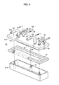
- the steam-generating device 30 is installed in the central portion of the hot air chamber 18 between the first heater 21 and the second heater 22. As shown in FIGS. 2 and 3, the steam-generating device 30 includes a heating tank 31 containing a designated quantity of water, a steam-generating heater 32 for heating the water contained in the heating tank 31, and a water level sensor 33 for sensing a water level in the heating tank 31.
- the heating tank 31 includes a heating container 31a having a rectangular hexahedral structure provided with an opened upper surface for containing water, and a cover member 31b provided with steam exhaust holes 34a and 34b respectively formed at both sides thereof for closing the opened upper surface of the heating container 31a.
- the cover member 31b is fixed to the inner rear surface of the hot air chamber 18 through fixing members 36 installed at upper portions of the rear surfaces of both sides thereof, and the heating container 31a is detachably attached to the lower portion of the cover member 31b. For this reason, a plurality of fixing bolts 37 which extend upwardly are fixed to the inside of the heating container 31a.
- fixing nuts 38 are respectively coupled with the upper ends of the corresponding fixing bolts 37, thereby fixing the fixing bolts 37.
- a packing member 39 for maintaining an airtight state is interposed between the upper end of the heating container 31a and the cover member 31b.
- Both ends of the steam-generating heater 32 are fixed to the cover member 31b such that the main portion of the steam-generating heater 32 can be submerged in water in the heating container 31a, and an end of the water level sensor 33 is fixed to the cover member 31b such that the main portion of the water level sensor 33 can be submerged in the water in the heating container 31a.
- a water supply hole 40 for supplying water to the heating container 31a therethrough is formed through the cover member 31b, and a water supply pipe 59c of the water supply device 50, which will be described later, is connected to the water supply hole 40.
- Exhaust guide pipes 35a and 35b having a designated length for guiding the exhaust of steam are respectively connected to steam exhaust holes 34a and 34b formed at both sides of the cover member 31 b.
- the steam-generating device 30 generates steam by heating water supplied to the heating tank 31a using the steam-generating heater 32, and supplies the steam to the cooking chamber 11 through the exhaust guide pipes 35a and 35b.
- the above steam-generating device 30 heats the outer surface of the heating tank 31 using the first and second heaters 21 and 22, thereby increasing efficiency in generating the steam, and uniformly supplies the steam exhausted through the exhaust guide pipes 35a and 35b to the cooking chamber 11 using the air circulating into the hot air chamber 18, thereby improving cooking effects.
- the water supply device 50 placed in the upper portion of the cooking chamber 11 includes a water bucket 51 having a bottle structure made of a transparent material, a water bucket-supporting device 52 placed on the upper portion of the front surface of the main body 10 for supporting the water bucket 51, a water supply pump 58 for supplying water of the water bucket-supporting device 52 to the heating tank 31 of the steam-generating device 30, and a plurality of water supply pipes 59a, 59b and 59c for connecting the water bucket-supporting device 52 and the water supply pump 58 and connecting the water supply pump 58 and the heating tank 31.
- the water bucket-supporting device 52 includes a switching member 53 installed on the upper portion of the front surface of the main body 10 and rotatably mounted for opening and closing the front surface of the main body 10, and a water container 54 installed on the inner side of the switching member 53 for receiving an inlet of the water bucket 51.
- the switching member 53 is drawn forwards when the front surface of the main body 10 is opened.
- a supporting shaft 53b of a lower end of the switching member 53 is rotatably connected to an opening formed in the upper portion of the front surface of the main body 10 such that the switching member 53 is rotated in a vertical direction through a designated angle and opened out of or closed to the front surface of the main body 10.
- a supporting portion 53a for supporting the water bucket 51 is formed on the upper portion of the inner part of the switching member 53 so that the supporting portion 53a can receive the inlet of the water bucket 51 under the condition that the switching member 53 is opened out of the front surface of the main body 10.
- the water container 54 may have a hexahedral structure as shown having an open upper surface forming a space for receiving the inlet of the water bucket 51 when the inlet of the water bucket 51 is introduced into the inside of the switching member 53.
- a supporting shaft 54a formed on the upper end of the water container 54 is rotatably connected to the switching member 53 such that the water container 54 is drawn forwardly when the switching member 53 is opened out of the front surface of the main body 10.
- the water supply pipe 59a is connected to the lower end of the rear portion of the water container 54 such that the water in the water container 54 is supplied to the water supply pump 58.
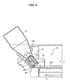
- the switching member 53 can be closed to the front surface of the main body 10, and when the user installs the water bucket 51 on the water bucket-supporting device 52, as shown in FIG. 4, the water bucket 51 is inserted into the water bucket-supporting device 52 such that the inlet of the water bucket 51 is directed to the lower surface of the water bucket-supporting device 52.
- the inlet of the water bucket 51 is introduced into the water container 54 and is then supported, the water of the water bucket 51 flows into the water container 54.
- a designated quantity of water is collected in the water container 54, and, when the water level in the water container 54 reaches the inlet of the water bucket 51, the introduction of the air into the water bucket 51 is interrupted, thereby preventing the water of the water bucket 51 from flowing into the water container 54.
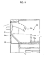
- the heating apparatus for cooking of the present embodiment also includes an inlet switching device 60 detachably attached to the inlet of the water bucket 51 for opening and closing the inlet of the water bucket 51, and a supporter 55 installed in the inner surface of the water container 54 for supporting the lower end of the inlet switching device 60 when the water bucket 51 is installed in the water bucket-supporting device 52.
- the inlet switching device 60 has a cylindrical structure having a designated length, and a valve member 61, for opening the inlet of the water bucket 51 when the water bucket 51 is put into the water container 54 and closing the inlet of the water bucket 51 when the water bucket 51 is taken out of the water container 54, is installed in the inlet switching device 60.
- the valve member 61 includes a valve plate 61a arranged to move back and forth by a designated distance to open and close the path of the inlet switching device 60, and a supporting rod 61b provided with one end fixed to the valve plate 61a and movably supported in the inlet switching device 60 to support the valve plate 61a.
- a protrusion 57 is formed on the supporter 55 in the water container 54, and presses the supporting rod 61b of the valve member 61 when the water bucket 51 is put into the water container 54, thereby opening the inlet of the water bucket 51.
- the above configuration of the inlet switching device 60 prevents water from flowing from the water bucket 51 when the water bucket 51 filled with the water is erected upside down and put into the water container 54, and allows the inlet of the water bucket 51 to be opened after the water bucket 51 is completely put into the water container 54.
- the inlet switching device 60 may be installed in conventional beverage containers, thereby allowing the conventional beverage containers to serve as water buckets. For this reason, the inlet switching device 60 could have a size suitable for being installed in the inlets of conventional beverage containers.
- a weight sensor 56 for sensing the weight of the water bucket 51 is installed in the supporter 55 for supporting the lower end of the inlet switching device 60.
- the weight sensor 56 determines whether or not the water bucket 51 is installed in the water container 54 and senses the weight of the water bucket 51, thereby sensing the quantity of the water in the water bucket 51.
- the upper and lower heaters 16a and 16b placed at the upper and lower portions of the cooking chamber 11 and the first and second heaters 21 and 22 placed in the hot air chamber 18 are operated and the first and second air blast fans 23a and 24a are operated.
- Food placed in the cooking chamber 11 is heated by heat generated from the upper and lower heaters 16a and 16b and hot air circulated through the hot air chamber 18 by the operation of the first and second air blast fans 23a and 24a.
- the user When a user wants to cook food in the cooking chamber 11 using steam supplied to the cooking chamber 11, the user installs the water bucket 51 on the water bucket-supporting device 52 placed at the upper portion of the cooking chamber 11 and manipulates the operating buttons 15b installed on the operating unit 15, thereby operating a steam generation mode. Then, water is supplied from the water container 54 to the heating tank 32 in the hot air chamber 18 by the operation of the water supply pump 58. Steam is generated by heating the steam-generating heater 32 in the heating tank 31, and is then supplied to the cooking chamber 11. Here, the steam is exhausted through the exhaust guide pipes 35a and 35b and uniformly supplied to the inside of the cooking chamber 11 through air circulating into the hot air chamber 18, thereby preventing the foods from being dried and improving cooking.
- Water in the heating tank 31 of the steam-generating device 30 of the present embodiment is heated by the first and second heaters 21 and 22 in the hot air chamber 18 as well as the steam-generating heater 32. Accordingly, since the water in the heating tank 31 is rapidly heated and efficiency in generating steam is improved, the steam-generating device 30 employs the steam-generating heater 32 having a low capacity and generates a sufficient quantity of steam.
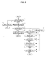
- FIG. 8 is a flowchart of a process for controlling the generation of steam in the heating apparatus for cooking in accordance with an embodiment of the present invention.
- the generation of steam will be described in detail.
- the process of FIG. 8 is performable by the apparatus of FIGS. 1-7 and is, for ease of explanation, described with concurrent reference to those figures. However, it is to be understood that the process of FIG. 9 is performable by other apparatus.
- a controller determines whether or not the water bucket 51 is installed on the water bucket-supporting device 52 using the weight sensor 56 placed in the water container 54 of the water bucket-supporting device 52 (S71). When it is determined that the water bucket 51 is not installed on the water supporting device 52, the controller sounds an alarm to the user (S72), and terminates the process.
- the alarm is displayed through the display 15a installed on the upper portion of the front surface of the main body 10, or is raised through a separate speaker (not shown) or lamp (not shown).
- the lamp may be arranged to flash on-and-off.
- the controller measures time elapsed from the time when the water bucket 51 is installed in the water container 54 (S73). Thereby, it is possible to know how long it has been since water in the water bucket 51 was replaced with new water. Then, the controller determines whether or not the time elapsed from the installation of the water bucket 51 exceeds a designated time (for example, 72 hours, etc.) (S74). When it is determined that the designated time has elapsed, the controller sounds an alarm to replace the water in the water bucket 51 with new water to the user (S75).
- a designated time for example, 72 hours, etc.
- Such an alarm informs the user of the deterioration of the water, which may be generated after a long period of time from the installation of the water bucket 51, thereby allowing the user to replace the water in the water bucket 51 with new water. Then the process returns to operation S71.
- the controller determines whether or not the quantity of the water in the water bucket 51 is sufficient using the weight sensor 56 installed in the water container 54 (S76). Then, when it is determined that the quantity of the water is insufficient, the controller sounds an alarm to supplement water (S77). Conversely, in case that it is determined that the quantity of the water is sufficient, the controller operates the water supply pump 58 so that water is supplied from the water container 54 to the heating tank 31 (S78).
- the controller senses the level of the water in the heating tank 31 using the water level sensor 33 of the heating tank 31, and determines whether or not the sensed level of the water is proper (S79).
- the controller continuously operates the water supply pump 58, and when the level of the water of the heating tank 58 is proper, the controller stops the operation of the water supply pump 58 (S80) and operates the steam-generating heater 32 so as to generate steam.
- the controller determines whether or not time designated by the user has elapsed (S82). When it is determined that the designated time has elapsed, the controller terminates the process, and when it is determined that the designated time has not elapsed, the controller continuously performs the water supply (S78) and operates the steam-generating heater 32 (S81).
- the heating apparatus for cooking of the present embodiment When the heating apparatus for cooking of the present embodiment does not perform the function of generating steam, the heating apparatus for cooking performs a function of removing residual water through the manipulation of the operating unit 15 so that the water in the water bucket-supporting device 52 and residual water in the heating tank 32 are removed, thereby being hygienically used.
- FIG. 9 a process for controlling the removal of residual water will be described in detail.
- the process may be performed by the apparatus of FIGS. 1-7 and is, for ease of explanation, described with reference to those figures. However, it is to be understood that the process can be performed by other apparatus.
- the controller determines whether or not the water bucket 15 is separated from the water bucket-supporting device 52 using the weight sensor 56 (S90). When it is determined that the water bucket 51 is not separated from the water bucket-supporting device 52, the controller sounds an alarm to separate the water bucket 51 from the water bucket-supporting device 52 (S91). When it is determined that the water bucket 51 is separated from the water bucket-supporting device 52, the controller operates the water supply pump 58 for a designated time so that all of the residual water in the water container 54 is supplied to the heating tank 31 (S92). Here, the operating time of the water supply pump 58 is sufficient to exhaust the water in the water container 54.
- the controller After the operation of the water supply pump 58, the controller operates the steam-generating heater 32 in the heating tank 31, thereby evaporating the water in the heating tank 31.
- the controller senses the level of the water of the heating tank 31 using the water level sensor 33 (S94) and determines whether or not residual water remains in the heating tank 31 (S95).
- the controller continuously operates the steam-generating heater 32, and when it is determined that the residual water does not remain in the heating tank 31, the controller terminates the operation of the steam-generating heater 32.
- the above-described embodiment of the present invention provides a heating apparatus for cooking having a water bucket of a water supply device, which is easily attached to and detached from the heating apparatus for cooking so that water supply is easily achieved, and is preferably made of a transparent material and exposed to the outside so that a user can easily know when water is supplied.
- the heating apparatus for cooking of the above-described embodiment of the present invention can completely remove residual water remaining in a steam-generating device and a water bucket-supporting device after steam-cooking is terminated, thereby being used hygienically.
- the heating apparatus for cooking of the present invention sounds an alarm indicating a time for replacing water with new water, thereby being used conveniently and safely.
Landscapes
- Engineering & Computer Science (AREA)
- Chemical & Material Sciences (AREA)
- Combustion & Propulsion (AREA)
- Mechanical Engineering (AREA)
- General Engineering & Computer Science (AREA)
- Food Science & Technology (AREA)
- Electric Ovens (AREA)
- Cookers (AREA)
- Commercial Cooking Devices (AREA)
Claims (5)
- Appareil de chauffage pour la cuisson, comprenant :- un corps principal (10) comprenant une chambre de cuisson (11);- un dispositif de génération de vapeur (30) qui fonctionne pour alimenter de la vapeur dans la chambre de cuisson (11) ; et- un dispositif d'alimentation d'eau (50) qui fonctionne pour alimenter de l'eau dans le dispositif de génération de vapeur (30), le dispositif d'alimentation d'eau (50) comprenant :- une cuve d'eau (51) pour contenir l'eau ;- un dispositif de support de cuve d'eau (52) installé sur le corps principal (10) pouvant être agencé pour supporter la cuve d'eau (51), et comprenant un espace pour maintenir une entrée de la cuve d'eau (51) de sorte que l'entrée est immergée dans l'eau lorsque la cuve d'eau (51) est insérée dans le dispositif de support de cuve d'eau (52) de sorte que l'entrée de la cuve d'eau (51) fait face à un fond du dispositif de support de cuve (52) ;- une pompe d'alimentation d'eau (58) pouvant fonctionner pour alimenter l'eau du dispositif de support de cuve d'eau (52) jusqu'au dispositif de génération de vapeur ;- des tuyaux d'alimentation d'eau (59) destinés à être utilisés pour guider l'eau du dispositif de support de cuve d'eau (52) jusqu'au dispositif de génération de vapeur (30) ; caractérisé en ce qu'il comprend en outre un capteur de poids (56) pour capter le poids de la cuve d'eau (51) lorsque la cuve d'eau est installée sur le dispositif de support de cuve d'eau (52).
- Appareil de chauffage pour cuisson selon la revendication 1, dans lequel le dispositif de support de cuve d'eau (52) comprend :- un élément de commutation (53) installé sur la partie supérieure de la surface avant du corps principal (10) pouvant être agencé pour ouvrir et fermer la surface avant du corps principal ; et- un récipient d'eau (54) raccordé à une surface interne de l'élément de commutation (53) pour recevoir l'entrée de la cuve d'eau lorsque la surface avant du corps principal (10) est ouverte, le récipient d'eau (54) pouvant être vidangé.
- Appareil de chauffage pour cuisson selon la revendication 2, comprenant en outre un dispositif de commutation d'entrée (60) fixé de manière détachable à l'entrée de la cuve d'eau (51), comprenant un élément de soupape (61) agencé pour s'ouvrir lorsque la cuve d'eau (51) est dans le récipient d'eau (54) et se fermer lorsque la cuve d'eau est séparée du récipient d'eau (54).
- Appareil de chauffage pour cuisson selon la revendication 3, dans lequel le récipient d'eau (54) comprend :- un dispositif de support (55) installé dans la surface interne du récipient d'eau (54) pour supporter une extrémité inférieure du dispositif de commutation d'entrée (60) ; et- une saillie (57) formée sur le dispositif de support (55) agencé pour comprimer l'élément de soupape (61) afin d'ouvrir l'entrée de la cuve d'eau (51) lorsque la cuve d'eau est placée dans le récipient d'eau (54).
- Appareil de chauffage pour cuisson selon la revendication 3 ou 4, dans lequel l'élément de soupape (61) comprend :- un organe formant clapet (61a) agencé pour avancer et reculer et ouvrir et fermer ainsi un passage du dispositif de commutation d'entrée (60) ; et- une tige de support (61b) ayant une longueur désignée et mobile d'avant en arrière, une extrémité de la tige de support (61b) étant fixée sur l'organe formant clapet (61a) afin de supporter l'organe formant clapet (61a).
Applications Claiming Priority (1)
| Application Number | Priority Date | Filing Date | Title |
|---|---|---|---|
| KR1020040054842A KR101132331B1 (ko) | 2004-07-14 | 2004-07-14 | 가열조리장치 및 그 제어방법 |
Publications (3)
| Publication Number | Publication Date |
|---|---|
| EP1616516A2 EP1616516A2 (fr) | 2006-01-18 |
| EP1616516A3 EP1616516A3 (fr) | 2006-01-25 |
| EP1616516B1 true EP1616516B1 (fr) | 2007-11-14 |
Family
ID=34941240
Family Applications (1)
| Application Number | Title | Priority Date | Filing Date |
|---|---|---|---|
| EP05252885A Expired - Lifetime EP1616516B1 (fr) | 2004-07-14 | 2005-05-11 | Appareil de cuisson et procédé pour sa commande |
Country Status (5)
| Country | Link |
|---|---|
| US (2) | US7091454B2 (fr) |
| EP (1) | EP1616516B1 (fr) |
| KR (1) | KR101132331B1 (fr) |
| CN (3) | CN100488420C (fr) |
| DE (1) | DE602005003267T2 (fr) |
Cited By (1)
| Publication number | Priority date | Publication date | Assignee | Title |
|---|---|---|---|---|
| EP2275745A1 (fr) | 2009-07-15 | 2011-01-19 | Electrolux Home Products Corporation N.V. | Four de cuisson avec au moins un dispositif de chauffage à convection |
Families Citing this family (71)
| Publication number | Priority date | Publication date | Assignee | Title |
|---|---|---|---|---|
| KR101132331B1 (ko) * | 2004-07-14 | 2012-04-05 | 삼성전자주식회사 | 가열조리장치 및 그 제어방법 |
| KR100598389B1 (ko) * | 2004-08-19 | 2006-07-06 | 삼성전자주식회사 | 과열증기조리기 |
| KR100807247B1 (ko) * | 2005-04-28 | 2008-02-28 | 삼성전자주식회사 | 수위감지장치 및 이를 구비한 증기조리장치 |
| US20060251784A1 (en) * | 2005-05-03 | 2006-11-09 | Sells Joel M | Method for cooking meat using steam |
| US7537004B2 (en) * | 2005-05-03 | 2009-05-26 | Whirlpool Corporation | Steam oven with fluid supply and drain vessel |
| US20060251785A1 (en) | 2005-05-06 | 2006-11-09 | Stefania Fraccon | Method for cooking food using steam |
| US20070175884A1 (en) * | 2006-01-31 | 2007-08-02 | Atul Saksena | Steam cooker with steam delivery device |
| KR100787746B1 (ko) * | 2006-06-19 | 2007-12-24 | 동양매직 주식회사 | 물통의 잔수 감지 구조를 갖는 스팀 오븐 |
| US20090250452A1 (en) * | 2006-08-08 | 2009-10-08 | Sze-Man Tse | Steam Convection Oven |
| KR101041078B1 (ko) * | 2006-09-27 | 2011-06-13 | 삼성전자주식회사 | 조리장치 및 그 제어방법 |
| KR101041079B1 (ko) * | 2006-09-28 | 2011-06-13 | 삼성전자주식회사 | 수위감지유닛과 이를 갖는 스팀발생장치 및 그스팀발생장치를 갖는 가열조리장치 |
| KR101041077B1 (ko) * | 2006-09-28 | 2011-06-13 | 삼성전자주식회사 | 스팀발생장치 및 이를 갖는 가열조리장치 |
| US7867534B2 (en) * | 2006-10-18 | 2011-01-11 | Whirlpool Corporation | Cooking appliance with steam generator |
| KR101253179B1 (ko) * | 2006-12-14 | 2013-04-12 | 엘지전자 주식회사 | 건조기 |
| KR101203840B1 (ko) * | 2006-12-14 | 2012-11-21 | 엘지전자 주식회사 | 세탁장치 및 그 제어방법 |
| KR100824006B1 (ko) * | 2006-12-29 | 2008-04-24 | 엘지전자 주식회사 | 스팀 오븐의 스팀 발생장치 |
| EP2150647B1 (fr) * | 2007-04-25 | 2016-09-07 | LG Electronics Inc. | Séchoir de blanchisserie à vapeur |
| KR101396971B1 (ko) * | 2007-05-02 | 2014-05-20 | 엘지전자 주식회사 | 스팀건조기 |
| GB0722934D0 (en) * | 2007-05-16 | 2008-01-02 | Otter Controls Ltd | Electrical appliances |
| KR101185557B1 (ko) * | 2007-10-09 | 2012-09-24 | 삼성전자주식회사 | 조리기기 및 그 제어방법 |
| US8207477B2 (en) | 2007-11-26 | 2012-06-26 | Whirlpool Corporation | Method for cooking vegetables using steam |
| US8006684B2 (en) * | 2007-12-10 | 2011-08-30 | Star Comgistic Capital Co. Ltd. | Superheated steam grill |
| DE102008050896A1 (de) * | 2008-09-25 | 2010-04-01 | Rieber Gmbh & Co. Kg | Dampferzeugungsvorrichtung und mobiles Speisenwarmhalte- und Speisengargerät |
| DE102009033253A1 (de) * | 2009-07-14 | 2011-02-17 | Caspar Cloer Gmbh & Co. Kg | Maschine zum Zubereiten von Heißgetränken |
| CN102472498B (zh) * | 2009-07-30 | 2015-06-24 | 夏普株式会社 | 加热烹调器 |
| DE102009055071A1 (de) * | 2009-12-21 | 2011-06-22 | BSH Bosch und Siemens Hausgeräte GmbH, 81739 | Haushaltsgerät |
| DE102009055074B4 (de) * | 2009-12-21 | 2020-01-09 | BSH Hausgeräte GmbH | Haushaltsgerät |
| DE102009055148A1 (de) | 2009-12-22 | 2011-06-30 | BSH Bosch und Siemens Hausgeräte GmbH, 81739 | Dampferzeugungssystem für ein Haushaltsgerät und Verfahren zum Montieren eines solchen Dampferzeugungssystems |
| RU2531415C2 (ru) * | 2010-04-28 | 2014-10-20 | Шарп Кабусики Кайся | Варочное устройство |
| FR2960140B1 (fr) * | 2010-05-18 | 2012-08-10 | Seb Sa | Dispositif de chauffage d?aliments a deux chambres superposees avec event |
| DE102010062888A1 (de) * | 2010-12-13 | 2012-06-14 | BSH Bosch und Siemens Hausgeräte GmbH | Wassertank für ein Dampfgargerät, Dampfgargerät mit einem derartigen Wassertank sowie Verfahren zum Entnehmen eines Wassertanks aus einer Aufnahme in einem Dampfgargerät |
| EP2550902B1 (fr) * | 2011-07-27 | 2014-07-02 | Electrolux Home Products Corporation N.V. | Pompe à eau et appareil comprenant un réservoir d'eau |
| EP2584270B1 (fr) * | 2011-10-19 | 2016-03-23 | MKN Maschinenfabrik Kurt Neubauer GmbH & Co. KG | Appareil de cuisine avec un raccordement pour des medias notamment électroniques et/ou électriques |
| KR101370414B1 (ko) * | 2012-09-28 | 2014-03-06 | 린나이코리아 주식회사 | 배수구 온도 측정을 통한 스팀 오븐 단수검지방법 |
| KR101981674B1 (ko) * | 2012-12-21 | 2019-05-24 | 삼성전자주식회사 | 조리기기 |
| ES2627327T3 (es) * | 2013-03-06 | 2017-07-27 | Lg Electronics, Inc. | Aparato de cocción por vapor |
| KR102067828B1 (ko) * | 2013-05-31 | 2020-02-11 | 엘지전자 주식회사 | 스팀 오븐 레인지 |
| EP2775217B1 (fr) * | 2013-03-06 | 2017-09-06 | LG Electronics Inc. | Appareil de cuisson à vapeur |
| DE102013215399B3 (de) * | 2013-08-06 | 2014-09-04 | Pasta E Sughi Sa | Dampferzeuger zum Erzeugen von Wasserdampf sowie Anlage zur Speisenzubereitung umfassend einen derartigen Dampferzeuger |
| CN103462519B (zh) * | 2013-08-21 | 2016-04-27 | 浙江安德电器有限公司 | 一种具有供水功能的蒸汽烤箱 |
| US9655468B2 (en) * | 2014-01-10 | 2017-05-23 | 2T2J, Inc. | Apparatus and process for rapidly cooking food |
| JP6480116B2 (ja) * | 2014-07-16 | 2019-03-06 | 株式会社村上開明堂 | ウォッシャー液の加熱装置 |
| KR101597104B1 (ko) * | 2014-12-19 | 2016-02-24 | 엘지전자 주식회사 | 의류처리장치의 제어방법 |
| CA2973550C (fr) | 2015-01-23 | 2023-09-26 | Balmuda Inc. | Dispositif de chauffage et de cuisson |
| US9788679B2 (en) | 2015-06-29 | 2017-10-17 | Whirlpool Corporation | Steam generation system for use in cooking appliance |
| WO2017116352A1 (fr) * | 2015-12-29 | 2017-07-06 | Arcelik Anonim Sirketi | Four comprenant un réservoir d'eau |
| CN205649397U (zh) | 2016-03-04 | 2016-10-19 | 飞利浦(中国)投资有限公司 | 空气炸锅 |
| KR102556053B1 (ko) * | 2016-09-09 | 2023-07-18 | 삼성전자주식회사 | 조리기기 및 그 제어방법 |
| KR102357903B1 (ko) * | 2017-05-19 | 2022-02-03 | 삼성전자주식회사 | 조리기기의 제어 방법 |
| CH713808B1 (de) * | 2017-05-22 | 2021-02-26 | Hauser Christoph | Multifunktionelles Gargerät. |
| DE202018006410U1 (de) | 2017-08-09 | 2020-04-23 | Sharkninja Operating Llc | Kochgerät und Komponenten davon |
| DE102017214932A1 (de) * | 2017-08-25 | 2019-02-28 | BSH Hausgeräte GmbH | Dampfgargerät |
| CN107495828A (zh) * | 2017-08-31 | 2017-12-22 | 苏州永博电气有限公司 | 一种蒸汽保湿型加热装置 |
| KR102455063B1 (ko) * | 2018-04-04 | 2022-10-14 | 엘지전자 주식회사 | 조리기기 및 그의 제어방법 |
| KR102699774B1 (ko) * | 2018-11-01 | 2024-08-29 | 엘지전자 주식회사 | 음료 제조기 |
| CN109008594A (zh) * | 2018-11-01 | 2018-12-18 | 杭州老板电器股份有限公司 | 具有蒸汽烹饪功能的烹饪电器及烘干控制方法 |
| KR102699779B1 (ko) * | 2018-11-05 | 2024-08-29 | 엘지전자 주식회사 | 음료 제조기 |
| CN109431295B (zh) * | 2018-11-12 | 2021-09-24 | 华帝股份有限公司 | 一种可消除冷凝水电蒸箱及控制方法 |
| CN109528135B (zh) * | 2018-11-16 | 2020-12-15 | 珠海格力电器股份有限公司 | 一种洗碗机除残留水系统及方法 |
| KR102133286B1 (ko) * | 2018-12-14 | 2020-07-13 | 엘지전자 주식회사 | 조리실의 자동 세척이 가능한 전자 조리 기기 |
| US10813490B2 (en) * | 2019-01-31 | 2020-10-27 | Whirlpool Corporation | Water inlet connectivity for steam oven |
| KR102164871B1 (ko) * | 2019-02-22 | 2020-10-14 | 김미영 | 증기 가열식 조리기기 |
| US20190254476A1 (en) | 2019-02-25 | 2019-08-22 | Sharkninja Operating Llc | Cooking device and components thereof |
| WO2020176477A1 (fr) | 2019-02-25 | 2020-09-03 | Sharkninja Operating Llc | Système de cuisson avec protection |
| KR102755455B1 (ko) * | 2019-04-10 | 2025-01-17 | 삼성전자주식회사 | 조리기기 |
| CN111802919B (zh) * | 2019-04-12 | 2022-07-15 | 华帝股份有限公司 | 蒸汽发生器余水排出控制方法、蒸汽发生器及蒸汽烹饪设备 |
| US11825976B2 (en) * | 2019-05-10 | 2023-11-28 | Electrolux Home Products, Inc. | Reservoir for steam cooking |
| CN112006529B (zh) * | 2019-05-31 | 2021-10-29 | 宁波方太厨具有限公司 | 一种蒸箱微波炉一体机 |
| US11647861B2 (en) | 2020-03-30 | 2023-05-16 | Sharkninja Operating Llc | Cooking device and components thereof |
| DE102020111622A1 (de) | 2020-04-29 | 2021-11-04 | Philipp Lampe | Vorrichtungen zum Aufgehenlassen einer Teigmasse |
| TR2024009561A2 (tr) * | 2024-07-24 | 2026-02-23 | Renta Elektrikli Ev Aletleri Sanayi Ve Dis Ticaret Ltd Sirketi | Buharli firinlarda su aktarim hortumu diş yüzeyi̇nden kilavuzlanabi̇lecek sizinti suyun güvenli̇ bi̇r bi̇çi̇mde tahli̇yesi̇ i̇çi̇n bi̇r terti̇bat |
Family Cites Families (29)
| Publication number | Priority date | Publication date | Assignee | Title |
|---|---|---|---|---|
| JPS5922132B2 (ja) | 1978-05-08 | 1984-05-24 | 株式会社東芝 | 蒸気発生器付高周波加熱装置 |
| ATE67580T1 (de) * | 1987-02-05 | 1991-10-15 | Juno Kuechentech Electrolux | Gargeraet mit elektrischer beheizung eines garraumes und verfahren zum betreiben dieses gargeraetes. |
| JPH0359146U (fr) * | 1989-10-16 | 1991-06-11 | ||
| KR910009438Y1 (ko) * | 1989-12-30 | 1991-12-09 | 삼립식품공업 주식회사 | 전기 찜통 |
| DE4303656B4 (de) * | 1993-02-09 | 2006-01-26 | Imperial-Werke Ohg | Haushaltsdampfgarer |
| JPH0681417U (ja) * | 1993-04-29 | 1994-11-22 | ホシザキ電機株式会社 | 蒸気調理機 |
| CN2172065Y (zh) * | 1993-10-06 | 1994-07-20 | 喻志坚 | 家庭用电蒸汽炉 |
| DE4420821A1 (de) | 1994-06-15 | 1995-12-21 | Bosch Siemens Hausgeraete | Backofen zum Dampfgaren |
| JPH094849A (ja) * | 1995-06-22 | 1997-01-10 | Matsushita Electric Ind Co Ltd | 加熱調理装置 |
| JP3603356B2 (ja) * | 1994-12-28 | 2004-12-22 | 松下電器産業株式会社 | 高周波加熱装置 |
| IN190221B (fr) * | 1995-06-22 | 2003-07-05 | Matsushita Electric Industrial Co Ltd | |
| KR0152145B1 (ko) * | 1995-07-10 | 1998-10-01 | 김광호 | 전자렌지 |
| KR0154643B1 (ko) * | 1995-09-29 | 1998-11-16 | 배순훈 | 증기센서의 출력신호를 이용한 적응 제어방법 |
| JP3751057B2 (ja) * | 1995-10-04 | 2006-03-01 | 松下電器産業株式会社 | マイクロ波加熱装置 |
| US5680810A (en) * | 1996-08-09 | 1997-10-28 | Sham; John C. K. | Steam toaster oven |
| EP0952400B1 (fr) * | 1996-09-03 | 2003-04-09 | Matsushita Electric Industrial Co., Ltd. | Dispositif de chauffage par micro-ondes |
| FR2754334B1 (fr) * | 1996-10-07 | 1998-12-18 | Bourgeois Prod Coop | Four a vapeur et convexion forcee |
| DE19741881C2 (de) * | 1997-09-23 | 2002-03-07 | Imp Werke Ohg | Haushaltgerät zum Dampfgaren |
| US6100502A (en) * | 1998-10-28 | 2000-08-08 | Wing Shing Products (Bvi) Co. Ltd. | Toaster oven with steam |
| US6157006A (en) * | 1998-11-04 | 2000-12-05 | Metro Industries, Inc. | High humidity apparatus |
| US6267046B1 (en) * | 2000-02-28 | 2001-07-31 | Conair Corporation | Convection steamer |
| KR100382280B1 (ko) | 2000-06-05 | 2003-05-01 | 김대인 | 컨벡션 오븐의 스팀발생장치 및 제어장치 |
| JP2003274884A (ja) | 2002-03-20 | 2003-09-30 | Isamu Nakano | 蒸気調理方法及び蒸気調理装置 |
| JP3731816B2 (ja) * | 2002-06-05 | 2006-01-05 | 松下電器産業株式会社 | 高周波加熱装置の給水制御方法及び高周波加熱装置 |
| JP3775352B2 (ja) | 2002-06-14 | 2006-05-17 | 松下電器産業株式会社 | 高周波加熱装置 |
| KR20050027460A (ko) * | 2003-09-15 | 2005-03-21 | 삼성전자주식회사 | 과열증기 조리장치 및 그 제어방법 |
| KR20050060560A (ko) * | 2003-12-16 | 2005-06-22 | 삼성전자주식회사 | 가열조리기 |
| KR101132331B1 (ko) * | 2004-07-14 | 2012-04-05 | 삼성전자주식회사 | 가열조리장치 및 그 제어방법 |
| US7537004B2 (en) * | 2005-05-03 | 2009-05-26 | Whirlpool Corporation | Steam oven with fluid supply and drain vessel |
-
2004
- 2004-07-14 KR KR1020040054842A patent/KR101132331B1/ko not_active Expired - Fee Related
-
2005
- 2005-05-05 US US11/122,049 patent/US7091454B2/en not_active Expired - Lifetime
- 2005-05-11 EP EP05252885A patent/EP1616516B1/fr not_active Expired - Lifetime
- 2005-05-11 DE DE602005003267T patent/DE602005003267T2/de not_active Expired - Lifetime
- 2005-05-18 CN CNB2007100920225A patent/CN100488420C/zh not_active Expired - Fee Related
- 2005-05-18 CN CNB200710092023XA patent/CN100453012C/zh not_active Expired - Fee Related
- 2005-05-18 CN CNB2005100713230A patent/CN1333203C/zh not_active Expired - Fee Related
-
2006
- 2006-06-27 US US11/475,065 patent/US7304271B2/en not_active Expired - Lifetime
Cited By (1)
| Publication number | Priority date | Publication date | Assignee | Title |
|---|---|---|---|---|
| EP2275745A1 (fr) | 2009-07-15 | 2011-01-19 | Electrolux Home Products Corporation N.V. | Four de cuisson avec au moins un dispositif de chauffage à convection |
Also Published As
| Publication number | Publication date |
|---|---|
| US7091454B2 (en) | 2006-08-15 |
| DE602005003267T2 (de) | 2008-09-11 |
| EP1616516A2 (fr) | 2006-01-18 |
| CN100488420C (zh) | 2009-05-20 |
| CN100453012C (zh) | 2009-01-21 |
| US20060237428A1 (en) | 2006-10-26 |
| KR20060005855A (ko) | 2006-01-18 |
| CN101028167A (zh) | 2007-09-05 |
| CN101028166A (zh) | 2007-09-05 |
| DE602005003267D1 (de) | 2007-12-27 |
| US20060011071A1 (en) | 2006-01-19 |
| KR101132331B1 (ko) | 2012-04-05 |
| US7304271B2 (en) | 2007-12-04 |
| CN1721768A (zh) | 2006-01-18 |
| EP1616516A3 (fr) | 2006-01-25 |
| CN1333203C (zh) | 2007-08-22 |
Similar Documents
| Publication | Publication Date | Title |
|---|---|---|
| EP1616516B1 (fr) | Appareil de cuisson et procédé pour sa commande | |
| US7323662B2 (en) | Heating apparatus for cooking | |
| CN107003005B (zh) | 加热烹调器 | |
| US6972397B2 (en) | Heating cooker | |
| JP4049787B2 (ja) | 過熱蒸気調理器 | |
| CN101784843B (zh) | 蒸汽烹调器 | |
| US7045745B2 (en) | Heating cooker having a steam generating unit | |
| JP2004333109A (ja) | 加熱調理器 | |
| JP4051384B2 (ja) | 過熱蒸気調理器 | |
| JP5405186B2 (ja) | 加熱調理器 | |
| JP6267309B2 (ja) | 蒸気調理器 | |
| KR100691224B1 (ko) | 증기조리장치 및 그 조리실 청소 방법 | |
| JP4559890B2 (ja) | 加熱調理器 | |
| JP2011058677A (ja) | 加熱調理器 | |
| JP2015206589A (ja) | 蒸気調理器 | |
| JP2024099092A (ja) | 架台 | |
| JP2014055764A (ja) | 蒸気調理器 | |
| JP2009041820A (ja) | 加熱調理器 |
Legal Events
| Date | Code | Title | Description |
|---|---|---|---|
| PUAI | Public reference made under article 153(3) epc to a published international application that has entered the european phase |
Free format text: ORIGINAL CODE: 0009012 |
|
| PUAL | Search report despatched |
Free format text: ORIGINAL CODE: 0009013 |
|
| AK | Designated contracting states |
Kind code of ref document: A2 Designated state(s): AT BE BG CH CY CZ DE DK EE ES FI FR GB GR HU IE IS IT LI LT LU MC NL PL PT RO SE SI SK TR |
|
| AX | Request for extension of the european patent |
Extension state: AL BA HR LV MK YU |
|
| AK | Designated contracting states |
Kind code of ref document: A3 Designated state(s): AT BE BG CH CY CZ DE DK EE ES FI FR GB GR HU IE IS IT LI LT LU MC NL PL PT RO SE SI SK TR |
|
| AX | Request for extension of the european patent |
Extension state: AL BA HR LV MK YU |
|
| 17P | Request for examination filed |
Effective date: 20060206 |
|
| AKX | Designation fees paid |
Designated state(s): DE FR GB |
|
| GRAP | Despatch of communication of intention to grant a patent |
Free format text: ORIGINAL CODE: EPIDOSNIGR1 |
|
| GRAS | Grant fee paid |
Free format text: ORIGINAL CODE: EPIDOSNIGR3 |
|
| GRAA | (expected) grant |
Free format text: ORIGINAL CODE: 0009210 |
|
| RIN1 | Information on inventor provided before grant (corrected) |
Inventor name: HONG, SEOK WEON Inventor name: CHO, PUNG YEUN Inventor name: HWANG, YUN IC Inventor name: SHOZO, KOBAYASHI Inventor name: KIM, CHEOL JIN Inventor name: HA, YU JEUB |
|
| AK | Designated contracting states |
Kind code of ref document: B1 Designated state(s): DE FR GB |
|
| REG | Reference to a national code |
Ref country code: GB Ref legal event code: FG4D |
|
| REF | Corresponds to: |
Ref document number: 602005003267 Country of ref document: DE Date of ref document: 20071227 Kind code of ref document: P |
|
| ET | Fr: translation filed | ||
| PLBE | No opposition filed within time limit |
Free format text: ORIGINAL CODE: 0009261 |
|
| STAA | Information on the status of an ep patent application or granted ep patent |
Free format text: STATUS: NO OPPOSITION FILED WITHIN TIME LIMIT |
|
| 26N | No opposition filed |
Effective date: 20080815 |
|
| REG | Reference to a national code |
Ref country code: FR Ref legal event code: PLFP Year of fee payment: 12 |
|
| REG | Reference to a national code |
Ref country code: FR Ref legal event code: PLFP Year of fee payment: 13 |
|
| REG | Reference to a national code |
Ref country code: DE Ref legal event code: R082 Ref document number: 602005003267 Country of ref document: DE Representative=s name: WUNDERLICH & HEIM PATENTANWAELTE PARTNERSCHAFT, DE |
|
| REG | Reference to a national code |
Ref country code: FR Ref legal event code: PLFP Year of fee payment: 14 |
|
| PGFP | Annual fee paid to national office [announced via postgrant information from national office to epo] |
Ref country code: DE Payment date: 20190423 Year of fee payment: 15 |
|
| PGFP | Annual fee paid to national office [announced via postgrant information from national office to epo] |
Ref country code: FR Payment date: 20190426 Year of fee payment: 15 |
|
| PGFP | Annual fee paid to national office [announced via postgrant information from national office to epo] |
Ref country code: GB Payment date: 20190424 Year of fee payment: 15 |
|
| REG | Reference to a national code |
Ref country code: DE Ref legal event code: R119 Ref document number: 602005003267 Country of ref document: DE |
|
| GBPC | Gb: european patent ceased through non-payment of renewal fee |
Effective date: 20200511 |
|
| PG25 | Lapsed in a contracting state [announced via postgrant information from national office to epo] |
Ref country code: GB Free format text: LAPSE BECAUSE OF NON-PAYMENT OF DUE FEES Effective date: 20200511 Ref country code: FR Free format text: LAPSE BECAUSE OF NON-PAYMENT OF DUE FEES Effective date: 20200531 |
|
| PG25 | Lapsed in a contracting state [announced via postgrant information from national office to epo] |
Ref country code: DE Free format text: LAPSE BECAUSE OF NON-PAYMENT OF DUE FEES Effective date: 20201201 |