EP1616536A2 - TMR Stent und zugehöriges Einführsystem - Google Patents
TMR Stent und zugehöriges Einführsystem Download PDFInfo
- Publication number
- EP1616536A2 EP1616536A2 EP05110421A EP05110421A EP1616536A2 EP 1616536 A2 EP1616536 A2 EP 1616536A2 EP 05110421 A EP05110421 A EP 05110421A EP 05110421 A EP05110421 A EP 05110421A EP 1616536 A2 EP1616536 A2 EP 1616536A2
- Authority
- EP
- European Patent Office
- Prior art keywords
- stent
- catheter
- distal end
- tissue
- tmr
- Prior art date
- Legal status (The legal status is an assumption and is not a legal conclusion. Google has not performed a legal analysis and makes no representation as to the accuracy of the status listed.)
- Withdrawn
Links
- 210000004165 myocardium Anatomy 0.000 claims abstract description 79
- 230000002107 myocardial effect Effects 0.000 claims abstract description 32
- 238000000034 method Methods 0.000 claims abstract description 31
- 239000008280 blood Substances 0.000 claims abstract description 23
- 210000004369 blood Anatomy 0.000 claims abstract description 23
- 210000005240 left ventricle Anatomy 0.000 claims abstract description 22
- 230000000250 revascularization Effects 0.000 claims abstract description 10
- 230000005012 migration Effects 0.000 claims abstract description 9
- 238000013508 migration Methods 0.000 claims abstract description 9
- 230000010412 perfusion Effects 0.000 claims description 13
- 238000002513 implantation Methods 0.000 claims description 8
- 230000007246 mechanism Effects 0.000 claims description 5
- 239000007943 implant Substances 0.000 claims description 4
- 230000037361 pathway Effects 0.000 claims description 4
- 229910001220 stainless steel Inorganic materials 0.000 claims description 4
- 239000010935 stainless steel Substances 0.000 claims description 4
- 238000004891 communication Methods 0.000 claims description 3
- 239000012530 fluid Substances 0.000 claims description 2
- 239000002991 molded plastic Substances 0.000 claims 2
- 238000005452 bending Methods 0.000 claims 1
- 229920000642 polymer Polymers 0.000 claims 1
- 210000001519 tissue Anatomy 0.000 description 66
- 230000017531 blood circulation Effects 0.000 description 13
- 238000003780 insertion Methods 0.000 description 8
- 230000037431 insertion Effects 0.000 description 8
- 230000001154 acute effect Effects 0.000 description 7
- 239000000463 material Substances 0.000 description 7
- 239000002184 metal Substances 0.000 description 5
- 210000003205 muscle Anatomy 0.000 description 5
- 230000035515 penetration Effects 0.000 description 5
- 239000004033 plastic Substances 0.000 description 4
- 229920003023 plastic Polymers 0.000 description 4
- 229910000619 316 stainless steel Inorganic materials 0.000 description 3
- 208000027418 Wounds and injury Diseases 0.000 description 3
- 238000013459 approach Methods 0.000 description 3
- 230000015572 biosynthetic process Effects 0.000 description 3
- 229920001903 high density polyethylene Polymers 0.000 description 3
- 239000004700 high-density polyethylene Substances 0.000 description 3
- 230000000302 ischemic effect Effects 0.000 description 3
- 239000002904 solvent Substances 0.000 description 3
- CSCPPACGZOOCGX-UHFFFAOYSA-N Acetone Chemical compound CC(C)=O CSCPPACGZOOCGX-UHFFFAOYSA-N 0.000 description 2
- 229910000589 SAE 304 stainless steel Inorganic materials 0.000 description 2
- 210000000078 claw Anatomy 0.000 description 2
- 208000014674 injury Diseases 0.000 description 2
- 238000007914 intraventricular administration Methods 0.000 description 2
- 238000005096 rolling process Methods 0.000 description 2
- 230000008733 trauma Effects 0.000 description 2
- 238000004804 winding Methods 0.000 description 2
- 239000010963 304 stainless steel Substances 0.000 description 1
- 239000004793 Polystyrene Substances 0.000 description 1
- 238000001467 acupuncture Methods 0.000 description 1
- 238000005219 brazing Methods 0.000 description 1
- 238000013130 cardiovascular surgery Methods 0.000 description 1
- 238000010586 diagram Methods 0.000 description 1
- 210000001174 endocardium Anatomy 0.000 description 1
- 238000005516 engineering process Methods 0.000 description 1
- 230000035876 healing Effects 0.000 description 1
- 238000005304 joining Methods 0.000 description 1
- 238000002406 microsurgery Methods 0.000 description 1
- 238000012986 modification Methods 0.000 description 1
- 230000004048 modification Effects 0.000 description 1
- 230000000149 penetrating effect Effects 0.000 description 1
- 229920002223 polystyrene Polymers 0.000 description 1
- 230000008569 process Effects 0.000 description 1
- 238000005086 pumping Methods 0.000 description 1
- 230000037390 scarring Effects 0.000 description 1
- 238000005476 soldering Methods 0.000 description 1
- 239000007787 solid Substances 0.000 description 1
- 238000001356 surgical procedure Methods 0.000 description 1
- 210000000115 thoracic cavity Anatomy 0.000 description 1
- 238000003466 welding Methods 0.000 description 1
Images







Classifications
-
- A—HUMAN NECESSITIES
- A61—MEDICAL OR VETERINARY SCIENCE; HYGIENE
- A61F—FILTERS IMPLANTABLE INTO BLOOD VESSELS; PROSTHESES; DEVICES PROVIDING PATENCY TO, OR PREVENTING COLLAPSING OF, TUBULAR STRUCTURES OF THE BODY, e.g. STENTS; ORTHOPAEDIC, NURSING OR CONTRACEPTIVE DEVICES; FOMENTATION; TREATMENT OR PROTECTION OF EYES OR EARS; BANDAGES, DRESSINGS OR ABSORBENT PADS; FIRST-AID KITS
- A61F2/00—Filters implantable into blood vessels; Prostheses, i.e. artificial substitutes or replacements for parts of the body; Appliances for connecting them with the body; Devices providing patency to, or preventing collapsing of, tubular structures of the body, e.g. stents
- A61F2/82—Devices providing patency to, or preventing collapsing of, tubular structures of the body, e.g. stents
- A61F2/94—Stents retaining their form, i.e. not being deformable, after placement in the predetermined place
-
- A—HUMAN NECESSITIES
- A61—MEDICAL OR VETERINARY SCIENCE; HYGIENE
- A61B—DIAGNOSIS; SURGERY; IDENTIFICATION
- A61B17/00—Surgical instruments, devices or methods
- A61B17/34—Trocars; Puncturing needles
- A61B17/3468—Trocars; Puncturing needles for implanting or removing devices, e.g. prostheses, implants, seeds, wires
-
- A—HUMAN NECESSITIES
- A61—MEDICAL OR VETERINARY SCIENCE; HYGIENE
- A61F—FILTERS IMPLANTABLE INTO BLOOD VESSELS; PROSTHESES; DEVICES PROVIDING PATENCY TO, OR PREVENTING COLLAPSING OF, TUBULAR STRUCTURES OF THE BODY, e.g. STENTS; ORTHOPAEDIC, NURSING OR CONTRACEPTIVE DEVICES; FOMENTATION; TREATMENT OR PROTECTION OF EYES OR EARS; BANDAGES, DRESSINGS OR ABSORBENT PADS; FIRST-AID KITS
- A61F2/00—Filters implantable into blood vessels; Prostheses, i.e. artificial substitutes or replacements for parts of the body; Appliances for connecting them with the body; Devices providing patency to, or preventing collapsing of, tubular structures of the body, e.g. stents
- A61F2/02—Prostheses implantable into the body
- A61F2/24—Heart valves ; Vascular valves, e.g. venous valves; Heart implants, e.g. passive devices for improving the function of the native valve or the heart muscle; Transmyocardial revascularisation [TMR] devices; Valves implantable in the body
- A61F2/2493—Transmyocardial revascularisation [TMR] devices
-
- A—HUMAN NECESSITIES
- A61—MEDICAL OR VETERINARY SCIENCE; HYGIENE
- A61B—DIAGNOSIS; SURGERY; IDENTIFICATION
- A61B17/00—Surgical instruments, devices or methods
- A61B17/00234—Surgical instruments, devices or methods for minimally invasive surgery
- A61B2017/00238—Type of minimally invasive operation
- A61B2017/00243—Type of minimally invasive operation cardiac
-
- A—HUMAN NECESSITIES
- A61—MEDICAL OR VETERINARY SCIENCE; HYGIENE
- A61B—DIAGNOSIS; SURGERY; IDENTIFICATION
- A61B17/00—Surgical instruments, devices or methods
- A61B17/00234—Surgical instruments, devices or methods for minimally invasive surgery
- A61B2017/00238—Type of minimally invasive operation
- A61B2017/00243—Type of minimally invasive operation cardiac
- A61B2017/00247—Making holes in the wall of the heart, e.g. laser Myocardial revascularization
-
- A—HUMAN NECESSITIES
- A61—MEDICAL OR VETERINARY SCIENCE; HYGIENE
- A61B—DIAGNOSIS; SURGERY; IDENTIFICATION
- A61B17/00—Surgical instruments, devices or methods
- A61B17/00234—Surgical instruments, devices or methods for minimally invasive surgery
- A61B2017/00349—Needle-like instruments having hook or barb-like gripping means, e.g. for grasping suture or tissue
-
- A—HUMAN NECESSITIES
- A61—MEDICAL OR VETERINARY SCIENCE; HYGIENE
- A61B—DIAGNOSIS; SURGERY; IDENTIFICATION
- A61B18/00—Surgical instruments, devices or methods for transferring non-mechanical forms of energy to or from the body
- A61B2018/00315—Surgical instruments, devices or methods for transferring non-mechanical forms of energy to or from the body for treatment of particular body parts
- A61B2018/00345—Vascular system
- A61B2018/00351—Heart
- A61B2018/00392—Transmyocardial revascularisation
-
- A—HUMAN NECESSITIES
- A61—MEDICAL OR VETERINARY SCIENCE; HYGIENE
- A61F—FILTERS IMPLANTABLE INTO BLOOD VESSELS; PROSTHESES; DEVICES PROVIDING PATENCY TO, OR PREVENTING COLLAPSING OF, TUBULAR STRUCTURES OF THE BODY, e.g. STENTS; ORTHOPAEDIC, NURSING OR CONTRACEPTIVE DEVICES; FOMENTATION; TREATMENT OR PROTECTION OF EYES OR EARS; BANDAGES, DRESSINGS OR ABSORBENT PADS; FIRST-AID KITS
- A61F2/00—Filters implantable into blood vessels; Prostheses, i.e. artificial substitutes or replacements for parts of the body; Appliances for connecting them with the body; Devices providing patency to, or preventing collapsing of, tubular structures of the body, e.g. stents
- A61F2/82—Devices providing patency to, or preventing collapsing of, tubular structures of the body, e.g. stents
- A61F2/848—Devices providing patency to, or preventing collapsing of, tubular structures of the body, e.g. stents having means for fixation to the vessel wall, e.g. barbs
-
- A—HUMAN NECESSITIES
- A61—MEDICAL OR VETERINARY SCIENCE; HYGIENE
- A61F—FILTERS IMPLANTABLE INTO BLOOD VESSELS; PROSTHESES; DEVICES PROVIDING PATENCY TO, OR PREVENTING COLLAPSING OF, TUBULAR STRUCTURES OF THE BODY, e.g. STENTS; ORTHOPAEDIC, NURSING OR CONTRACEPTIVE DEVICES; FOMENTATION; TREATMENT OR PROTECTION OF EYES OR EARS; BANDAGES, DRESSINGS OR ABSORBENT PADS; FIRST-AID KITS
- A61F2/00—Filters implantable into blood vessels; Prostheses, i.e. artificial substitutes or replacements for parts of the body; Appliances for connecting them with the body; Devices providing patency to, or preventing collapsing of, tubular structures of the body, e.g. stents
- A61F2/82—Devices providing patency to, or preventing collapsing of, tubular structures of the body, e.g. stents
- A61F2002/826—Devices providing patency to, or preventing collapsing of, tubular structures of the body, e.g. stents more than one stent being applied sequentially
-
- A—HUMAN NECESSITIES
- A61—MEDICAL OR VETERINARY SCIENCE; HYGIENE
- A61F—FILTERS IMPLANTABLE INTO BLOOD VESSELS; PROSTHESES; DEVICES PROVIDING PATENCY TO, OR PREVENTING COLLAPSING OF, TUBULAR STRUCTURES OF THE BODY, e.g. STENTS; ORTHOPAEDIC, NURSING OR CONTRACEPTIVE DEVICES; FOMENTATION; TREATMENT OR PROTECTION OF EYES OR EARS; BANDAGES, DRESSINGS OR ABSORBENT PADS; FIRST-AID KITS
- A61F2220/00—Fixations or connections for prostheses classified in groups A61F2/00 - A61F2/26 or A61F2/82 or A61F9/00 or A61F11/00 or subgroups thereof
- A61F2220/0008—Fixation appliances for connecting prostheses to the body
- A61F2220/0016—Fixation appliances for connecting prostheses to the body with sharp anchoring protrusions, e.g. barbs, pins, spikes
-
- A—HUMAN NECESSITIES
- A61—MEDICAL OR VETERINARY SCIENCE; HYGIENE
- A61F—FILTERS IMPLANTABLE INTO BLOOD VESSELS; PROSTHESES; DEVICES PROVIDING PATENCY TO, OR PREVENTING COLLAPSING OF, TUBULAR STRUCTURES OF THE BODY, e.g. STENTS; ORTHOPAEDIC, NURSING OR CONTRACEPTIVE DEVICES; FOMENTATION; TREATMENT OR PROTECTION OF EYES OR EARS; BANDAGES, DRESSINGS OR ABSORBENT PADS; FIRST-AID KITS
- A61F2220/00—Fixations or connections for prostheses classified in groups A61F2/00 - A61F2/26 or A61F2/82 or A61F9/00 or A61F11/00 or subgroups thereof
- A61F2220/0025—Connections or couplings between prosthetic parts, e.g. between modular parts; Connecting elements
- A61F2220/0058—Connections or couplings between prosthetic parts, e.g. between modular parts; Connecting elements soldered or brazed or welded
Definitions
- This invention relates to a system for revascularizing myocardial tissue.
- a system for revascularizing myocardial tissue comprises stents placeable in tissue to provide patent channels for revascularization of the tissue.
- the invention also relates to a system for delivering the stents to the intended site within a patient.
- TMR Transmyocardial Revascularization
- the intraventricular pump comprises tubes that swing radially outwards and protrude from a hub after the pump has been pushed out of the catheter.
- the tips of the tubes pierce the endocardium and myocardium and become embedded in the myocardium.
- the tubes become anchored to the myocardium such that they can act to inject blood into the myocardium wall from the ventricle.
- the TMR stent and associated delivery system of the present invention provide a simplified mechanism for creating revascularizing channels in the myocardium by implanting self-piercing stents directly into ischemic tissue.
- the invention comprises a self-piercing stent delivered into the myocardium to stimulate blood flow directly to the tissue from the left ventricle.
- the stents are self-piercing, a separate channel need not be formed into the tissue prior to stent placement.
- the stents are rigid and expansion from a reduced delivery diameter to a larger diameter for implantation into a preformed channel is not necessary. Rather, a sharp distal tip enables each stent to pierce the tissue and imbed itself when it is pushed into the myocardium.
- the stents may have a length that corresponds to a penetration depth approximately equal to three-quarters of the thickness of the myocardium.
- a flange may be included at the proximal end of the stent that catches the surface of the myocardium to ensure that the stent is not inserted too deeply into the tissue.
- the hollow interior of the imbedded stents provides a passageway through which blood may pass from the ventricle into the tissue.
- Perfusion capability may be enhanced by piercing radially extending channels through enlarged side ports of the implanted stent using a sharp tip wire inserted through the proximal opening of the stent.
- the stent can be formed from a flexible helically coiled spring.
- Various materials and cross-sectional shapes can be used for the spring ribbon that is wrapped into a helical shape.
- the overall shape of the coiled stent can be varied, though at least a portion of the stent should be tapered to the distal end to form a pointed tip that facilitates penetration into the myocardium.
- Outward migration of the coiled stent after insertion is prevented by configuring the stent to have tissue engaging protrusions on its outside surface.
- the ribbon used to form the coiled stent may be canted away from parallel to the longitudinal axis of the stent to create a raised edge on each coil.
- the coils of the stent form a saw tooth outer surface on the stent.
- the mandrel upon which the ribbon is wrapped can be configured with a ribbed spiral surface that holds each coil in the canted configuration.
- the ribbon may be placed in tension during wrapping on a mandrel to cause the edges of the coils to curve outward and protrude from the stent body.
- a ribbon of trapezoidal cross-section can be wrapped about a straight mandrel so that the surface of each coil of the resulting spring has a raised edge.
- the surface of each coil is configured to project outward at an angle to the longitudinal axis of the stent.
- Each coil has an outwardly projecting raised edge angled in the proximal direction. Therefore, the raised edges of the stent coils will not catch onto the tissue during distal movement of the stent into the myocardium, but will claw into tissue to resist proximal movement of the stent out of the myocardium occurs.
- Some embodiments of the wrapped coil stent may be sufficiently flexible to require support of a piercing delivery device positioned within the stent interior during implantation into the myocardium.
- the TMR stents are delivered to the heart transluminally by a delivery catheter, avoiding the need for surgery.
- the pointed stents may be configured to be nested within each other for tandem containment within the delivery catheter, thereby permitting delivery of stents at multiple locations in the myocardium with one catheterization.
- the delivery catheter may be guided to the left ventricle by tracking a previously inserted barbed tip guidewire anchored in the myocardium. After reaching the ventricle, the distal tip of the catheter may be steered to different points on the surface of the myocardium to deliver the several stents over an area of ischemic tissue.
- the pushing force needed to eject the stents from the distal end of the delivery catheter and into the myocardium may be exerted through a push wire that is slidable through the catheter.
- a restraint mechanism for preventing inadvertent discharge of the stents from the catheter may include a sheath having inwardly projecting resilient fingers to restrain the stent under light to moderate forces. Application of delivery force pushes the leading of the nested stents past the resilient fingers and into the tissue.
- FIG. 1 shows, in diagrammatic section, the left ventricle 2 of a human heart 1.
- the TMR stents 8 of the present invention are implanted through the endocardial surface 6 into myocardial tissue 4 to provide pathways for blood to flow directly from the ventricle into the tissue for the purpose of revascularization. Blood flowing from the ventricle through the hollow stent 8 perfuses into the tissue surrounding the stent. The perfusion of blood revitalizes ischemic tissue, if that tissue has remained viable despite the previous deprivation of blood.
- the TMR stent 8 is cylindrically or conically shaped having a hollow interior 17 for blood flow and a pointed distal end for piercing and embedding into myocardial tissue.
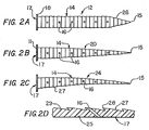
- FIG. 2A shows a preferred TMR stent 12 that is molded having a body 14 that is straight with a distal taper 26 and perfusion holes 16.
- a molded stent 20 may have a body 14 that is straight with full taper as shown in FIG. 2B.
- a third variation of a molded stent 24 may have a body 14 that is conical and has a slight curvature along its longitudinal axis with a full taper, similar to a quill, as shown in FIG. 2C.
- a flange 18 located at the proximal end of the stents becomes flush with the endocardial surface of the myocardium upon implantation to control insertion depth of the stent.
- the pointed distal tip 15 may be open to provide another perfusion hole through the stent.
- the conical shape of the stents shown in FIGS. 2A-2C is significant in that it permits multiple stents to be nested, one distal end arranged within the proximal end of the next.
- the pointed end of each stent may reside partially within the open cone shape interior 17 of the next stent to permit multiple stent delivery through a sheath or catheter. Additionally, the pointed configuration of the stent enables penetration of the myocardial tissue, without prior formation of a channel into the tissue.
- the molded TMR stent is preferably formed from a plastic material such as high density polyethylene (HDPE).
- the length of the stent may be approximately 1.0 centimeter and is intended to correspond to a penetration depth of approximately 75% of the thickness of the myocardium.
- the maximum outside diameter of the body of the tapered stent is on the order of .060"-.070" (0.1524 - 0.1778 centimeter).
- the diameter of the flange portion 18, on the order of .080" -.100" (0.2032 - 0.254 centimeter) is larger than the body portion to catch the endocardial surface of the myocardium and prevent the stent from being inserted too deeply.
- the force required to insert the stents into the myocardium is on the order of 0.2 pounds (0.89 Newton).
- Circumferential ridges 27 formed along the length of the molded stents serve as small proximally facing barbs 28.
- FIG. 2D a detailed cross section of the side wall of the molded of FIGS. 2A-2C is shown.
- the barbs project outward in a proximal direction, at an angle acute to the side surface 29 of the stent so as not to hamper insertion.
- the orientation of the barbs causes them to grip the surrounding tissue to prevent the stent from migrating in a proximal direction out of the myocardium after implantation.
- Perfusion holes 16 may be formed throughout the body 14 of the stent to permit blood flow, entering the interior 17 of an implanted stent from the ventricle, to flow radially outward into the myocardial tissue.
- the perfusion holes are on the order of .004" - .010.” (0.01016 - 0.0254 centimeter) in diameter and may pass through the stent side wall at an angle, as shown in FIG. 2D, or may be perpendicular to the longitudinal axis of the stent.
- the number of holes may be varied but it is believed that blood flow is improved by maximizing their quantity.
- FIG. 3 shows a preferred molded TMR stent 20 having a body 14 that is straight with a full taper, and having perfusion holes 16 and enlarged side port 42 to increase blood flow out of the stent. Blood flow from the stents into the myocardium may be further enhanced by puncturing channels into the tissue surrounding the implanted stent.
- FIGS. 3A through 3C are longitudinal cross-sectional views of implanted molded stents 20 with directing channels 43 joining the enlarged side ports 42 to the open proximal end 11 of the stent.
- a piercing tube or wire 48 is guided distally through the delivery catheter 46, into the directing channels 43 which direct the piercing tip to the enlarged side ports 42 to penetrate the myocardium 4 (FIG 3B).
- the piercing wire should be introduced through the stent immediately after implantation while still in alignment with the delivery catheter.
- the piercing tube creates radial channels 49 in the myocardium extending from the side ports 42. Creation of the radial channels 49 forms a defined, continuous blood pathway to the myocardium 4 from the ventricle 2 via the directing channels 43 and side ports 42 of the stent. It is believed that the defined pathway extended by the radial channels 49 promotes increased blood flow into the myocardium.
- TMR stent 31 has a cylindrically or conically shaped body 37 having a hollow interior 39 for blood flow and a pointed distal end 40 for piercing and embedding into myocardial tissue.
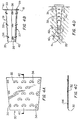
- the TMR stent is fabricated by rolling a perforated metal sheet 30, shown in FIG. 4A, into a tapered, tubular shape stent 31 shown in FIG. 4B.
- the metal sheet 30 may be a material such as 304 stainless steel having a thickness on the order of .0005" - .003" (0.00127 - 0.00762 centimeter).
- the stent also may be formed from a sheet of suitable plastic material such as HDPE.
- Perforations 32 may be etched or stamped into the sheet while in a flat configuration.
- Perforations 32 are shaped to have a triangular barb 34. After formation of the perforations 32, the triangular barb shapes 34 may be bent out of plane from the metal sheet as shown by the sectional view shown in FIG. 4C. The bent triangular shapes 34 serve to locate the implanted stent as projecting barbs. The perforations 32 serve as perfusion outlets through which blood can flow out of the stent.
- FIG. 4D shows an implanted rolled TMR stent 31 having an enlarged side port 42 for increased blood flow into the myocardial tissue 4.
- Eyelets 36 and locking tabs 38 are formed at the edges of the flat sheet to provide a mechanism for holding the rolled sheet in a tubular configuration. As shown in FIG. 4B, once the sheet is rolled, locking tabs 38 hook into eyelets 36, locking in place under the resilient expansion force of the rolled sheet.
- the length of the stent is approximately 1.0 centimeter, maximum outside diameter is on the order of .060"-.070" (0.1524 - 0.1778 centimeter) and the diameter of the flange portion 18 is, on the order of .080" - .100" (0.2032 - 0.254 centimeter).
- the tapered tubular shape of the stent provides a proximal opening 33, through which blood enters from the ventricle, and an opening 35 at the piercing distal end 40 to provide an additional perfusion outlet into the tissue.
- a flange 41 at the proximal end of the stent can help maintain stent depth in the myocardium such that the proximal opening 33 is in fluid communication with the left ventricle.
- Raised barbs 34 project outward from the tubular stent at an acute angle to the axis of the stent, pointing towards the proximal end of the stent.
- the angular orientation of the barbs 34 permits insertion of the stent into tissue (in the distal direction) but prevents migration of the stent back out of the tissue in the proximal direction, as the barbs will hook into the tissue.
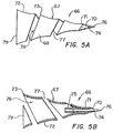
- a TMR stent 66 comprises a body 67 formed from a helically wound flat ribbon 68 as shown in Fig. 5A.
- the ribbon is formed into a conical shape by wrapping it around a tapered mandrel (not shown) to cause plastic deformation.
- the ribbon 68 is wound with an increasing diameter as it extends proximally, providing the stent with a generally conical shape and hollow interior 78.
- a suitable material for the ribbon is 304 or 316 stainless steel having a thickness of approximately .003" (0.00762 centimeter) and a width of approximately .005" - .015" (0.0127 - 0.0381 centimeter)
- the distal end 71 of the ribbon is bonded at joint 70 by soldering, brazing or welding to a central mandrel 74 that extends partially through the interior of the stent.
- a stainless steel mandrel may be used having a diameter of approximately .012" (0.03048 centimeter).
- the distal tip 76 of the mandrel is sharpened to provide the stent with a piercing tip capable of penetrating the myocardium.
- the proximal end of the mandrel is bonded to a short segment of hypodermic tubing 75 to facilitate nesting of additional stents for multiple stent delivery.
- the hypotube may have an outside diameter of approximately .020" (0.0508 centimeter) and inside diameter of approximately .015" (0.0381 centimeter) to provide a suitable receptacle for the distal tip of another stent nested behind.
- the proximal end 79 of the ribbon may be soldered, brazed or welded upon itself to maintain the conical, wrapped configuration. Delivery force is applied in a distal direction, internally to the stent through the hypotube 75 and central mandrel 74. Spaces 77 between the wrappings of the ribbon permit blood to flow from the interior of the stent outward into the surrounding tissue of the myocardium.
- the stainless steel ribbon material may be placed in tension during the initial winding process to deform the ribbon to have a curved cross-sectional shape as is shown in FIG. 5B.
- the concave surface 72 of the ribbon creates flared edges 73 which act as barbs to grasp the tissue once the stent is implanted.
- a helically wrapped stent 59 shown in Figs. 6A and 6B can be formed by wrapping the ribbon 61 around a mandrel 50 having a ribbed spiral surface 52 to cause plastic deformation of the ribbon as shown in Fig 6C. Wrapping the ribbon around the mandrel forms a stent body 55 comprised of several helically arranged coils 62 spaced slightly apart. The spaces 77 between the coils 62 of the ribbon permit blood to flow from the interior 78 of the stent outward into the surrounding tissue of the myocardium also serve to make the stent more flexible so that it can move with the myocardial tissue.
- the wrapping mandrel 50 has several annular ribs 54 around its surface 52 that serve to hold each coil 62 of the ribbon 61.
- Each rib 54 has a frusto-conical surface 57 having a small diameter portion 58 and a large diameter portion 56.
- the frusto-conical surface 57 of each rib 54 extends away from the longitudinal axis of the mandrel at an acute angle.
- the ribbon 61 has a rectangular cross-section. The principal axis of the rectangular cross section is maintained at an acute angle to the longitudinal axis of the mandrel about which the ribbon is deformed.
- each coil 62 fits into a rib 54 and is maintained at the acute angle that the frusto-conical surface makes with the longitudinal axis of the wrapping mandrel 50.
- the resulting coiled ribbon presents a raised edge 63 at the proximal side of each coil.
- a saw tooth surface configuration is formed along the length of the stent to resist forces that tend to push the stent back out of the myocardium after it has been inserted.
- the orientation of the canted coils presents the recessed edge 64 as the leading edge when the stent is moved in the distal direction such as during insertion into the tissue.
- the raised edge 63 is presented as the leading edge if the stent is urged proximally out of the tissue so that the edge becomes anchored onto the tissue to resist movement.
- the wrapping mandrel 50 may be made dissolvable so that it can be easily removed from the interior 78 of the completed spring stent 59 about which it has been wrapped. Because each coil 62 of the stent is wrapped firmly into the ribs 54, sliding or unwinding the stent off the mandrel is difficult. A dissolvable mandrel can be broken down and washed away from within the completed stent by application of a solvent. The structure of the dissolvable mandrel can be fortified during stent wrapping by a removable rigid core (not shown). The core is inserted through a central bore 60 of the mandrel to provide added stiffness while the stent is wrapped.
- the core can be slid out from the bore 60 and solvent applied to the mandrel.
- the dissolvable mandrel can be machined or molded from polystyrene, with acetone as a suitable solvent.
- the ribbon 61 is wound with an increasing diameter as it extends proximally, providing the stent 59 with a generally conical shape.
- various configurations of the conical shape are possible with the wrapped spring TMR stent embodiment.
- Various combinations of barrels, tapers, shoulders and arcs can be employed in the shape of the stent to make it easily insertable into the myocardium while also making it resistant to withdrawal.
- a preferred stent may be on the order of 0.35" (0.889 centimeter) in length and .06" (0.1524 centimeter) in maximum diameter.
- the stent 59 may be formed with a flange 65 at its proximal end 69 to prevent insertion of the stent too deeply into the myocardium.
- the flange having a wider diameter than the rest of the stent, is intended to become flush with the endocardial surface of the myocardium as the stent is inserted.
- a coil spring body 81 having a raised edge 83 at the proximal end of each coil 84 is formed by wrapping a ribbon 82 of trapezoidal cross-section around a smooth mandrel. Though the trapezoidal shape ribbon lies flat on the smooth mandrel 88, as shown in Fig 8C, the tapered thickness of the ribbon causes it to become canted so that the proximal edge 83 of each coil 84 to be raised further from the stent central axis than the distal coil edge 89.
- each canted coil 84 serves to anchor the implanted stent in the myocardium similarly to the raised edges 63 of the coils of the previous stent embodiment.
- Trapezoidal 316 stainless steel winding wire is a suitable material for this stent embodiment. Dimensions of the trapezoidal cross-section should be on the order of 0.010" (0.0254 centimeter) wide with a maximum thickness on the order of 0.002" (0.00508 centimeter) and a minimum thickness on the order of 0.001" (0.00254 centimeter).
- Figs. 9A - 9D show another wrapped spring stent embodiment 90.
- the stent 90 is formed by wrapping a rectangular cross-sectional wire around a ribbed mandrel, similar to the embodiment shown in FIG. 6C.
- the long axis 93 of the rectangular cross-section ribbon is oriented substantially perpendicular to the longitudinal axis 94 of the stent, as is shown in Figs. 9A - 9D.
- the major axis 93 of the coils 91 of the rectangular ribbon 92 tend to extend radially from the longitudinal axis of the stent 90 at an acute angle.
- the stent is preferably formed from 316 stainless steel rectangular cross-section forming wire.
- the stent 90 may be as long as 0.35" (0.889 centimeter) in length and as wide as 0.09" (0.2286 centimeter) in diameter.
- the stent of Figs. 9A-9D does not employ a central mandrel and hypotube. Therefore, the stent 90 is not readily nestable with other stents for multiple stent delivery, nor is it self-piercing. Instead, this stent embodiment is delivered one at a time while placed over a piercing mandrel delivery device 96 as shown in Figs. 9C and 9D.
- the delivery device comprises a body 95 to support the stent coils 92, a sharpened tip 99 for piercing the myocardium and a backstop 98 to keep the stent 90 from sliding off the back of the device 96 when the assembly is pushed into the myocardium.
- the delivery device simultaneously pierces the myocardium and implants a stent, as occurs during delivery of the other stent embodiments.
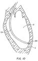
- All TMR stent embodiments described above can be delivered to the myocardium percutaneously and transluminally through the left ventricle of the heart as shown diagrammatically in Fig. 10.
- the delivery system comprises a steerable catheter with an inner sheath and pusher wire to deliver multiple self-piercing stents.
- a barbed tip guidewire anchored in the myocardium guides the deflectable tip catheter to the intended area.
- the rotation of the catheter around the eccentrically oriented guidewire provides a circumferential area within which the delivery system can implant stents into the myocardial tissue. Up to ten stents or more may be implantable with one catheterization to revascularize an area of myocardial tissue. Because the stents delivered are self-piercing, no prior channel creation through the delivery catheter is required before stent delivery.
- a guide catheter 101 is first navigated through the patient's vessels to reach the left ventricle 2 of the heart as shown in FIG. 10.
- a barbed tip guidewire 104 is then inserted through the guide catheter and into the ventricle where it pierces the myocardium 4 and becomes anchored within the tissue.
- the guidewire 104 may be fabricated of stainless steel and have a diameter of approximately .020" (0.0508 centimeter).
- the barbed shape formed at the distal tip should be sharp enough to easily penetrate the myocardium but resist removal from the tissue at forces of at least up to 0.2 pounds (0.89 Newton) (the stent delivery force).
- a stop 115 is bonded near the distal end of the guidewire prevents excessive penetration into the myocardium.
- the guide catheter is withdrawn and a steerable stent delivery catheter 106 shown in FIG. 11A is advanced over the guidewire 104 to become positioned within the ventricle for stent delivery.
- the guidewire lumen 108 of the catheter is oriented eccentrically on the catheter 106. Therefore, when the catheter is rotated about the guidewire 104, the center of the catheter 106 rotates through a circular path 118 as is shown in FIG. 11 B to encompass a broader delivery area with one guidewire placement.
- the outside diameter of the delivery catheter is preferably less than .100" (0.254 centimeter).
- Steering capability is provided by a pull wire 122 extending the length of the catheter in lumen 120 and terminating in a bond 124 near the distal tip of the catheter. Pulling the wire 122 from the proximal end causes the more flexible distal tip of the delivery catheter 106 to buckle, thereby providing steering control.
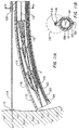
- the deflectable tip catheter 106 has a large central lumen 110 which slidably receives a flexible inner sheath 111.
- the distal end of the flexible sheath has several resilient fingers 116 located around the circumference of the sheath projecting distally and inwardly toward the center of the lumen to restrain stents 8 loaded within the catheter.
- Within the inner sheath slides a push wire 114 having a ball 112 near its distal end for engaging the interior of a TMR stent 8
- the push rod 114 and inner sheath 111 are advanced distally in unison to move a stent 8 out of the catheter 106 as shown in FIG. 12B.
- the distal tip of the inner sheath 111 projects slightly from the catheter 106 during delivery.
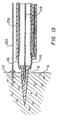
- the stents of the embodiment of FIGS. 3 - 3C cannot be nested due to directing channels formed in their interior and, thus are delivered singularly as shown in Fig. 13.
- the canted wrapped spring stent embodiment 90 shown in Figs. 9A - 9D is also delivered singularly, through the delivery catheter, carried over the piercing delivery device 95 shown in Fig. 9C. Rather than being self-piercing like the other stent embodiments, the canted spring stent 90 is delivered over the delivery device 95 which simultaneously pierces the tissue and delivers the stent into the opened tissue. For all stent embodiments, a force of approximately 0.2 pounds (0.89 Newton) should be sufficient to embed the stent embodiments into the myocardium.
- stents may be delivered sequentially to multiple sites in the myocardium through a single placement of the delivery catheter 106 within the ventricle 2. Initially, the delivery catheter 106 is advanced over the barbed tip guidewire 104 to a site on the surface of the myocardium 4. The distal tip of the delivery catheter is brought into close proximity to the myocardial tissue and a first stent is delivered in accordance with the steps described above.
- the delivery catheter 106 is withdrawn slightly in the proximal direction and is rotated about the eccentrically positioned guidewire 104 as depicted in FIGS. 14C and 14D.
- the distal tip of the delivery catheter 106 may also be deflected by the pull wire mechanism to provide additional range of movement.
- the catheter 106 is advanced to the myocardium 4 and the next stent is delivered, again following the steps detailed above. This procedure is repeated for the delivery of the remaining stents throughout the circumferential area defined by the catheter's rotation around the eccentric guidewire. As many as ten stents or more may be delivered within such an area with a single catheterization.
- the guidewire is withdrawn proximally from the myocardial tissue and the catheter and guidewire are removed from the patient.
- the invention provides a stent and associated delivery system for aiding revascularization of myocardial tissue of the heart.
- the stents are simple and readily insertable into the myocardium with a minimum of steps.
- the delivery system is simple to operate to implant multiple stents quickly.
Landscapes
- Health & Medical Sciences (AREA)
- Engineering & Computer Science (AREA)
- Biomedical Technology (AREA)
- Life Sciences & Earth Sciences (AREA)
- General Health & Medical Sciences (AREA)
- Cardiology (AREA)
- Veterinary Medicine (AREA)
- Heart & Thoracic Surgery (AREA)
- Public Health (AREA)
- Animal Behavior & Ethology (AREA)
- Transplantation (AREA)
- Vascular Medicine (AREA)
- Oral & Maxillofacial Surgery (AREA)
- Surgery (AREA)
- Pathology (AREA)
- Nuclear Medicine, Radiotherapy & Molecular Imaging (AREA)
- Medical Informatics (AREA)
- Molecular Biology (AREA)
- Media Introduction/Drainage Providing Device (AREA)
- Prostheses (AREA)
- Surgical Instruments (AREA)
Applications Claiming Priority (6)
| Application Number | Priority Date | Filing Date | Title |
|---|---|---|---|
| US4599297P | 1997-05-08 | 1997-05-08 | |
| US4600397P | 1997-05-08 | 1997-05-08 | |
| US4599197P | 1997-05-08 | 1997-05-08 | |
| US4686697P | 1997-05-08 | 1997-05-08 | |
| US7330998P | 1998-01-29 | 1998-01-29 | |
| EP19980201480 EP0876803B1 (de) | 1997-05-08 | 1998-05-06 | TMR Stent und zugehöriges Einführsystem |
Related Parent Applications (1)
| Application Number | Title | Priority Date | Filing Date |
|---|---|---|---|
| EP19980201480 Division EP0876803B1 (de) | 1997-05-08 | 1998-05-06 | TMR Stent und zugehöriges Einführsystem |
Publications (2)
| Publication Number | Publication Date |
|---|---|
| EP1616536A2 true EP1616536A2 (de) | 2006-01-18 |
| EP1616536A3 EP1616536A3 (de) | 2008-12-17 |
Family
ID=27534917
Family Applications (2)
| Application Number | Title | Priority Date | Filing Date |
|---|---|---|---|
| EP05110421A Withdrawn EP1616536A3 (de) | 1997-05-08 | 1998-05-06 | TMR Stent und zugehöriges Einführsystem |
| EP19980201480 Expired - Lifetime EP0876803B1 (de) | 1997-05-08 | 1998-05-06 | TMR Stent und zugehöriges Einführsystem |
Family Applications After (1)
| Application Number | Title | Priority Date | Filing Date |
|---|---|---|---|
| EP19980201480 Expired - Lifetime EP0876803B1 (de) | 1997-05-08 | 1998-05-06 | TMR Stent und zugehöriges Einführsystem |
Country Status (8)
| Country | Link |
|---|---|
| EP (2) | EP1616536A3 (de) |
| JP (1) | JPH11244392A (de) |
| CN (1) | CN1321619C (de) |
| BR (1) | BR9804941A (de) |
| CA (1) | CA2259914C (de) |
| DE (1) | DE69835251T2 (de) |
| ES (1) | ES2270492T3 (de) |
| WO (1) | WO1998049964A1 (de) |
Cited By (14)
| Publication number | Priority date | Publication date | Assignee | Title |
|---|---|---|---|---|
| US7704222B2 (en) | 1998-09-10 | 2010-04-27 | Jenavalve Technology, Inc. | Methods and conduits for flowing blood from a heart chamber to a blood vessel |
| US10993805B2 (en) | 2008-02-26 | 2021-05-04 | Jenavalve Technology, Inc. | Stent for the positioning and anchoring of a valvular prosthesis in an implantation site in the heart of a patient |
| US11065138B2 (en) | 2016-05-13 | 2021-07-20 | Jenavalve Technology, Inc. | Heart valve prosthesis delivery system and method for delivery of heart valve prosthesis with introducer sheath and loading system |
| US11185405B2 (en) | 2013-08-30 | 2021-11-30 | Jenavalve Technology, Inc. | Radially collapsible frame for a prosthetic valve and method for manufacturing such a frame |
| US11197754B2 (en) | 2017-01-27 | 2021-12-14 | Jenavalve Technology, Inc. | Heart valve mimicry |
| US11337800B2 (en) | 2015-05-01 | 2022-05-24 | Jenavalve Technology, Inc. | Device and method with reduced pacemaker rate in heart valve replacement |
| US11357624B2 (en) | 2007-04-13 | 2022-06-14 | Jenavalve Technology, Inc. | Medical device for treating a heart valve insufficiency |
| US11517431B2 (en) | 2005-01-20 | 2022-12-06 | Jenavalve Technology, Inc. | Catheter system for implantation of prosthetic heart valves |
| US11564794B2 (en) | 2008-02-26 | 2023-01-31 | Jenavalve Technology, Inc. | Stent for the positioning and anchoring of a valvular prosthesis in an implantation site in the heart of a patient |
| US11589981B2 (en) | 2010-05-25 | 2023-02-28 | Jenavalve Technology, Inc. | Prosthetic heart valve and transcatheter delivered endoprosthesis comprising a prosthetic heart valve and a stent |
| US12121461B2 (en) | 2015-03-20 | 2024-10-22 | Jenavalve Technology, Inc. | Heart valve prosthesis delivery system and method for delivery of heart valve prosthesis with introducer sheath |
| US12171658B2 (en) | 2022-11-09 | 2024-12-24 | Jenavalve Technology, Inc. | Catheter system for sequential deployment of an expandable implant |
| US12414854B2 (en) | 2010-05-20 | 2025-09-16 | Jenavalve Technology, Inc. | Catheter system for introducing an expandable stent into the body of a patient |
| US12616593B2 (en) | 2021-07-15 | 2026-05-05 | Jenavalve Technology, Inc. | Heart valve prosthesis delivery system and method for delivery of heart valve prosthesis with introducer sheath and loading system |
Families Citing this family (39)
| Publication number | Priority date | Publication date | Assignee | Title |
|---|---|---|---|---|
| US6991614B2 (en) | 1995-11-07 | 2006-01-31 | Boston Scientific Scimed, Inc. | Ureteral stent for improved patient comfort |
| US6849069B1 (en) | 1995-11-07 | 2005-02-01 | Boston Scientitfic Corporation | Medical device with tail(s) for assisting flow of urine |
| US5755682A (en) | 1996-08-13 | 1998-05-26 | Heartstent Corporation | Method and apparatus for performing coronary artery bypass surgery |
| US5980548A (en) * | 1997-10-29 | 1999-11-09 | Kensey Nash Corporation | Transmyocardial revascularization system |
| WO2000015146A1 (en) * | 1998-09-10 | 2000-03-23 | Percardia, Inc. | Transmyocardial shunt for left ventricular revascularization |
| ATE322230T1 (de) | 1998-09-10 | 2006-04-15 | Percardia Inc | Tmr vorrichtung |
| US6290728B1 (en) | 1998-09-10 | 2001-09-18 | Percardia, Inc. | Designs for left ventricular conduit |
| US6196230B1 (en) | 1998-09-10 | 2001-03-06 | Percardia, Inc. | Stent delivery system and method of use |
| US6641610B2 (en) | 1998-09-10 | 2003-11-04 | Percardia, Inc. | Valve designs for left ventricular conduits |
| US6692520B1 (en) * | 1998-12-15 | 2004-02-17 | C. R. Bard, Inc. | Systems and methods for imbedded intramuscular implants |
| US7578828B2 (en) | 1999-01-15 | 2009-08-25 | Medtronic, Inc. | Methods and devices for placing a conduit in fluid communication with a target vessel |
| US6468271B1 (en) | 1999-02-24 | 2002-10-22 | Scimed Life Systems, Inc. | Device and method for percutaneous myocardial revascularization |
| US6217575B1 (en) | 1999-02-24 | 2001-04-17 | Scimed Life Systems, Inc. | PMR catheter |
| US6332892B1 (en) | 1999-03-02 | 2001-12-25 | Scimed Life Systems, Inc. | Medical device with one or more helical coils |
| US6620170B1 (en) | 1999-04-26 | 2003-09-16 | C. R. Bard, Inc. | Devices and methods for treating ischemia by creating a fibrin plug |
| US6409697B2 (en) | 1999-05-04 | 2002-06-25 | Heartstent Corporation | Transmyocardial implant with forward flow bias |
| JP2003505195A (ja) * | 1999-07-30 | 2003-02-12 | シー・アール・バード・インク | インプラント係留システムの改良 |
| US6638237B1 (en) | 1999-08-04 | 2003-10-28 | Percardia, Inc. | Left ventricular conduits and methods for delivery |
| US6253768B1 (en) | 1999-08-04 | 2001-07-03 | Percardia, Inc. | Vascular graft bypass |
| US7033372B1 (en) | 1999-08-04 | 2006-04-25 | Percardia, Inc. | Corkscrew reinforced left ventricle to coronary artery channel |
| US6709427B1 (en) | 1999-08-05 | 2004-03-23 | Kensey Nash Corporation | Systems and methods for delivering agents into targeted tissue of a living being |
| US6605053B1 (en) | 1999-09-10 | 2003-08-12 | Percardia, Inc. | Conduit designs and related methods for optimal flow control |
| US6428569B1 (en) | 1999-11-09 | 2002-08-06 | Scimed Life Systems Inc. | Micro structure stent configurations |
| US7226475B2 (en) | 1999-11-09 | 2007-06-05 | Boston Scientific Scimed, Inc. | Stent with variable properties |
| US6854467B2 (en) | 2000-05-04 | 2005-02-15 | Percardia, Inc. | Methods and devices for delivering a ventricular stent |
| US7204847B1 (en) | 2000-07-28 | 2007-04-17 | C. R. Bard, Inc. | Implant anchor systems |
| US6533779B2 (en) | 2001-01-16 | 2003-03-18 | Scimed Life Systems, Inc. | PMR catheter and associated methods |
| US6976990B2 (en) | 2001-01-25 | 2005-12-20 | Percardia, Inc. | Intravascular ventriculocoronary bypass via a septal passageway |
| US6544220B2 (en) | 2001-02-14 | 2003-04-08 | Scimed Life Systems, Inc. | Fluid jet PMR |
| US6719804B2 (en) | 2001-04-02 | 2004-04-13 | Scimed Life Systems, Inc. | Medical stent and related methods |
| US6620202B2 (en) | 2001-10-16 | 2003-09-16 | Scimed Life Systems, Inc. | Medical stent with variable coil and related methods |
| US6949118B2 (en) | 2002-01-16 | 2005-09-27 | Percardia, Inc. | Encased implant and methods |
| US7008397B2 (en) | 2002-02-13 | 2006-03-07 | Percardia, Inc. | Cardiac implant and methods |
| US7326219B2 (en) | 2002-09-09 | 2008-02-05 | Wilk Patent Development | Device for placing transmyocardial implant |
| IES20030531A2 (en) | 2003-07-17 | 2005-09-21 | Medtronic Vascular Connaught | Methods and devices for placing a fistula device in fluid communication with a target vessel |
| IES20030539A2 (en) | 2003-07-22 | 2005-05-18 | Medtronic Vascular Connaught | Stents and stent delivery system |
| DE602004023302D1 (de) * | 2003-08-11 | 2009-11-05 | Wilson Cook Medical Inc | Chirurgisches implantat |
| FR2862521B1 (fr) * | 2003-11-24 | 2006-09-22 | Juan Carlos Chachques | Catheter de diagnostic et d'injection, notamment pour application cardiologique a coeur battant |
| CN101961269B (zh) * | 2010-04-19 | 2012-09-05 | 杭州启明医疗器械有限公司 | 用于输送人造瓣膜置换装置的输送装置 |
Family Cites Families (13)
| Publication number | Priority date | Publication date | Assignee | Title |
|---|---|---|---|---|
| FR1514319A (fr) * | 1967-01-11 | 1968-02-23 | Dispositif pour l'implantation dans la région apicale du coeur d'un ventricule artificiel | |
| DK163713C (da) * | 1987-09-02 | 1992-09-07 | Ole Gyring Nieben | Anordning til anbringelse af et partielt kateter i et legemshulrum |
| US4889137A (en) * | 1988-05-05 | 1989-12-26 | The United States Of America As Reprsented By The Department Of Health And Human Services | Method for improved use of heart/lung machine |
| US5052998A (en) * | 1990-04-04 | 1991-10-01 | Zimmon David S | Indwelling stent and method of use |
| US5380316A (en) * | 1990-12-18 | 1995-01-10 | Advanced Cardiovascular Systems, Inc. | Method for intra-operative myocardial device revascularization |
| US5324325A (en) * | 1991-06-27 | 1994-06-28 | Siemens Pacesetter, Inc. | Myocardial steroid releasing lead |
| US5287861A (en) * | 1992-10-30 | 1994-02-22 | Wilk Peter J | Coronary artery by-pass method and associated catheter |
| FR2725615B1 (fr) * | 1994-10-17 | 1997-06-13 | Caffiniere Jean Yves De | Dispositif d'ancrage osseux des fils de fixation utilises en chirurgie orthopedique |
| US5810836A (en) * | 1996-03-04 | 1998-09-22 | Myocardial Stents, Inc. | Device and method for trans myocardial revascularization (TMR) |
| IL118352A0 (en) * | 1996-05-21 | 1996-09-12 | Sudai Amnon | Apparatus and methods for revascularization |
| US5655645A (en) * | 1996-09-27 | 1997-08-12 | Foster; Raymond Keith | Seal member for reciprocating slat conveyors |
| DE29619029U1 (de) * | 1996-11-02 | 1997-04-10 | Kletke, Georg, Dr.med., 24534 Neumünster | Nadel zur Miokardpunktion |
| US5980548A (en) * | 1997-10-29 | 1999-11-09 | Kensey Nash Corporation | Transmyocardial revascularization system |
-
1998
- 1998-05-04 WO PCT/US1998/008819 patent/WO1998049964A1/en not_active Ceased
- 1998-05-04 BR BR9804941A patent/BR9804941A/pt not_active Application Discontinuation
- 1998-05-04 CN CNB988009463A patent/CN1321619C/zh not_active Expired - Fee Related
- 1998-05-04 CA CA002259914A patent/CA2259914C/en not_active Expired - Fee Related
- 1998-05-06 EP EP05110421A patent/EP1616536A3/de not_active Withdrawn
- 1998-05-06 DE DE1998635251 patent/DE69835251T2/de not_active Expired - Lifetime
- 1998-05-06 EP EP19980201480 patent/EP0876803B1/de not_active Expired - Lifetime
- 1998-05-06 ES ES98201480T patent/ES2270492T3/es not_active Expired - Lifetime
- 1998-05-07 JP JP16411698A patent/JPH11244392A/ja not_active Withdrawn
Cited By (24)
| Publication number | Priority date | Publication date | Assignee | Title |
|---|---|---|---|---|
| US7736327B2 (en) | 1998-09-10 | 2010-06-15 | Jenavalve Technology, Inc. | Methods and conduits for flowing blood from a heart chamber to a blood vessel |
| US8216174B2 (en) | 1998-09-10 | 2012-07-10 | Jenavalve Technology, Inc. | Methods and conduits for flowing blood from a heart chamber to a blood vessel |
| US8597226B2 (en) | 1998-09-10 | 2013-12-03 | Jenavalve Technology, Inc. | Methods and conduits for flowing blood from a heart chamber to a blood vessel |
| US7704222B2 (en) | 1998-09-10 | 2010-04-27 | Jenavalve Technology, Inc. | Methods and conduits for flowing blood from a heart chamber to a blood vessel |
| US12569336B2 (en) | 2005-01-20 | 2026-03-10 | Jenavalve Technology, Inc. | Catheter system for implantation of prosthetic heart valves |
| US11517431B2 (en) | 2005-01-20 | 2022-12-06 | Jenavalve Technology, Inc. | Catheter system for implantation of prosthetic heart valves |
| US11357624B2 (en) | 2007-04-13 | 2022-06-14 | Jenavalve Technology, Inc. | Medical device for treating a heart valve insufficiency |
| US11564794B2 (en) | 2008-02-26 | 2023-01-31 | Jenavalve Technology, Inc. | Stent for the positioning and anchoring of a valvular prosthesis in an implantation site in the heart of a patient |
| US11154398B2 (en) | 2008-02-26 | 2021-10-26 | JenaValve Technology. Inc. | Stent for the positioning and anchoring of a valvular prosthesis in an implantation site in the heart of a patient |
| US10993805B2 (en) | 2008-02-26 | 2021-05-04 | Jenavalve Technology, Inc. | Stent for the positioning and anchoring of a valvular prosthesis in an implantation site in the heart of a patient |
| US12232957B2 (en) | 2008-02-26 | 2025-02-25 | Jenavalve Technology, Inc. | Stent for the positioning and anchoring of a valvular prosthesis in an implantation site in the heart of a patient |
| US12414854B2 (en) | 2010-05-20 | 2025-09-16 | Jenavalve Technology, Inc. | Catheter system for introducing an expandable stent into the body of a patient |
| US11589981B2 (en) | 2010-05-25 | 2023-02-28 | Jenavalve Technology, Inc. | Prosthetic heart valve and transcatheter delivered endoprosthesis comprising a prosthetic heart valve and a stent |
| US12447015B2 (en) | 2010-05-25 | 2025-10-21 | Jenavalve Technology, Inc. | Prosthetic heart valve and transcatheter delivered endoprosthesis comprising a prosthetic heart valve and a stent |
| US11185405B2 (en) | 2013-08-30 | 2021-11-30 | Jenavalve Technology, Inc. | Radially collapsible frame for a prosthetic valve and method for manufacturing such a frame |
| US12318281B2 (en) | 2013-08-30 | 2025-06-03 | Jenavalve Technology, Inc. | Radially collapsible frame for a prosthetic valve and method for manufacturing such a frame |
| US12121461B2 (en) | 2015-03-20 | 2024-10-22 | Jenavalve Technology, Inc. | Heart valve prosthesis delivery system and method for delivery of heart valve prosthesis with introducer sheath |
| US11337800B2 (en) | 2015-05-01 | 2022-05-24 | Jenavalve Technology, Inc. | Device and method with reduced pacemaker rate in heart valve replacement |
| US12343255B2 (en) | 2015-05-01 | 2025-07-01 | Jenavalve Technology, Inc. | Device and method with reduced pacemaker rate in heart valve replacement |
| US11065138B2 (en) | 2016-05-13 | 2021-07-20 | Jenavalve Technology, Inc. | Heart valve prosthesis delivery system and method for delivery of heart valve prosthesis with introducer sheath and loading system |
| US12433745B2 (en) | 2017-01-27 | 2025-10-07 | Jenavalve Technology, Inc. | Heart valve mimicry |
| US11197754B2 (en) | 2017-01-27 | 2021-12-14 | Jenavalve Technology, Inc. | Heart valve mimicry |
| US12616593B2 (en) | 2021-07-15 | 2026-05-05 | Jenavalve Technology, Inc. | Heart valve prosthesis delivery system and method for delivery of heart valve prosthesis with introducer sheath and loading system |
| US12171658B2 (en) | 2022-11-09 | 2024-12-24 | Jenavalve Technology, Inc. | Catheter system for sequential deployment of an expandable implant |
Also Published As
| Publication number | Publication date |
|---|---|
| BR9804941A (pt) | 1999-08-24 |
| CN1321619C (zh) | 2007-06-20 |
| CA2259914A1 (en) | 1998-11-12 |
| EP0876803B1 (de) | 2006-07-19 |
| EP0876803A2 (de) | 1998-11-11 |
| CN1230879A (zh) | 1999-10-06 |
| WO1998049964A1 (en) | 1998-11-12 |
| DE69835251T2 (de) | 2007-06-14 |
| JPH11244392A (ja) | 1999-09-14 |
| DE69835251D1 (de) | 2006-08-31 |
| WO1998049964A9 (en) | 1999-03-25 |
| ES2270492T3 (es) | 2007-04-01 |
| CA2259914C (en) | 2007-12-18 |
| EP0876803A3 (de) | 1999-04-28 |
| EP1616536A3 (de) | 2008-12-17 |
Similar Documents
| Publication | Publication Date | Title |
|---|---|---|
| EP0876803B1 (de) | TMR Stent und zugehöriges Einführsystem | |
| EP1098673B1 (de) | Wirkstoffabgabesysteme | |
| US7204847B1 (en) | Implant anchor systems | |
| EP1117350B1 (de) | Biegsames transmyokardimplantat zur induktion der angiogenese | |
| EP1117352B1 (de) | Biegsames transmyokardimplantat zur induktion der angiogenese | |
| US7452325B2 (en) | Catheter-based tissue remodeling devices and methods | |
| US7232421B1 (en) | Agent delivery systems | |
| CN106901875B (zh) | 心脏瓣膜修复设备及方法 | |
| JP2002543912A (ja) | インプラント係留システム | |
| WO2001008602A1 (en) | Improved implant anchor systems | |
| WO2001010350A1 (en) | Implant and agent delivery device | |
| MXPA99000459A (es) | Perforador de tmr y sistema de suministro | |
| RU99102248A (ru) | Стент для трансмиокардной реваскуляризации (tmr) и система его доставки |
Legal Events
| Date | Code | Title | Description |
|---|---|---|---|
| PUAI | Public reference made under article 153(3) epc to a published international application that has entered the european phase |
Free format text: ORIGINAL CODE: 0009012 |
|
| AC | Divisional application: reference to earlier application |
Ref document number: 0876803 Country of ref document: EP Kind code of ref document: P |
|
| AK | Designated contracting states |
Kind code of ref document: A2 Designated state(s): DE ES FR GB IT NL |
|
| RIC1 | Information provided on ipc code assigned before grant |
Ipc: A61F 2/94 20060101ALI20080820BHEP Ipc: A61F 2/06 20060101AFI20051124BHEP |
|
| PUAL | Search report despatched |
Free format text: ORIGINAL CODE: 0009013 |
|
| AK | Designated contracting states |
Kind code of ref document: A3 Designated state(s): DE ES FR GB IT NL |
|
| AKX | Designation fees paid | ||
| REG | Reference to a national code |
Ref country code: DE Ref legal event code: 8566 |
|
| STAA | Information on the status of an ep patent application or granted ep patent |
Free format text: STATUS: THE APPLICATION IS DEEMED TO BE WITHDRAWN |
|
| 18D | Application deemed to be withdrawn |
Effective date: 20090618 |