EP1617010A2 - Soupirail avec accessoire - Google Patents
Soupirail avec accessoire Download PDFInfo
- Publication number
- EP1617010A2 EP1617010A2 EP05015409A EP05015409A EP1617010A2 EP 1617010 A2 EP1617010 A2 EP 1617010A2 EP 05015409 A EP05015409 A EP 05015409A EP 05015409 A EP05015409 A EP 05015409A EP 1617010 A2 EP1617010 A2 EP 1617010A2
- Authority
- EP
- European Patent Office
- Prior art keywords
- light shaft
- attachment
- bulges
- indentations
- region
- Prior art date
- Legal status (The legal status is an assumption and is not a legal conclusion. Google has not performed a legal analysis and makes no representation as to the accuracy of the status listed.)
- Granted
Links
Images






Classifications
-
- E—FIXED CONSTRUCTIONS
- E04—BUILDING
- E04F—FINISHING WORK ON BUILDINGS, e.g. STAIRS, FLOORS
- E04F17/00—Vertical ducts; Channels, e.g. for drainage
- E04F17/06—Light shafts, e.g. for cellars
Definitions
- the present invention relates to a light shaft made of plastic, which can be attached to a building wall and the building side and in the upper area is open. Furthermore, the present invention relates to an attachment made of plastic for a light shaft and a set consisting of the light shaft and the attachment and a method for mounting the set.
- Light wells of the type indicated above have been known for many years and are arranged on buildings, for example, in the area of basement windows. In recent times, the light wells are exposed to increasingly higher loads, in particular during the construction phase, because, for example, excavation pits are nowadays no longer filled by hand, but mechanically by excavators or caterpillars.
- the light shaft according to the invention can be attached to a building wall and open in its upper area.
- the lateral surface of the light shaft according to the invention is designed so that it is continuously curved at least to the lower area at least two-dimensionally.
- a two-dimensional curvature in the sense of the invention is, for example, a body whose cross section is, for example, the subsegment of a circle or an ellipse.
- the jacket can be curved not only two but also three-dimensional.
- Three-dimensionally curved moldings can, for. B. cutouts from the lateral surface of an ovaloid, a ball od.
- the lateral surface is designed vaulted.
- the light shaft In the lower area of the light shaft can also be curved in three dimensions. But it is also conceivable that the light shaft is designed in the lower area as a straight, not curved surface, for example, followed by a radius and then merges into the curved part of the lateral surface of the light shaft.
- the lateral surface of the light shaft in the upper region is designed semicircular.
- the light shaft in the area with which it rests against the building wall, a circumferential flange, which preferably extends parallel to the building wall.
- this flange has either a sealing means or, for example, a groove or the like, into which a sealing agent can be introduced. The sealant prevents. the moisture penetrates between the flange and the building wall.
- the light shaft fastening means which are particularly preferably formed on the right and left of the flange. Most preferably, these fasteners are hook-shaped. With the fasteners, the light shaft can be attached to the building wall.
- the light shaft has at its outer periphery, particularly preferably in the upper region, at least two rows of several indentations or bulges.
- These indentations or bulges can, as described in detail below, co-operate with indentations or bulges of an attachment, which is placed on the light shaft, positively and / or non-positively.
- the indentations or bulges are designed tooth-shaped.
- a row with a plurality of indentations or bulges is arranged on the transition region between the lateral surface and flange in the upper region of the light shaft.
- one or two rows with a plurality of indentations or bulges are arranged in the region of the lateral surface, preferably symmetrically with respect to its central axis.
- the light shaft in the upper region preferably has a preferably angled shaping, which stabilizes the light shaft in this area, if it is statically and / or dynamically loadable.
- spacers are preferably arranged on the outer circumference of the light shaft so that a plurality of light shafts can be stacked on one another, for example for storage and / or during transport.
- the light shaft has ribs which, as explained in greater detail below, serve as a lateral guide for stabilizing the attachment.
- the light well according to the invention and the components described below can be made of any plastic.
- the plastic is glass fiber reinforced plastic, more preferably polyester.
- gratings can be placed, which are compatible with the cross-sectional shape of the light shaft in the upper region, preferably round or semicircular gratings
- the light shaft according to the invention is extremely resilient, since it has an at least substantially continuously curved lateral surface. At the light shaft according to the invention essays can be arranged and adjusted in height.
- the light shaft according to the invention is simple and inexpensive to manufacture and attach to the corresponding building wall.
- the light shaft according to the invention can be extended particularly well with an essay in its height.
- Another object of vodiegenden invention is therefore a plastic article for a light shaft, which can be attached to a building wall and the building side is open and which can be connected in its lower part with a light shaft and assignable in the upper part with a grid, with his Jacket surface in the upper region has a rectangular cross-section and in the lower region has an at least two-dimensionally curved lateral surface.
- the article of the invention is simple and inexpensive to manufacture and can be easily arranged on the light shaft according to the invention.
- the article according to the invention is statically very high load capacity.
- the attachment In its upper region, the attachment has an angular, preferably rectangular Querschitt, so that it can be assigned in particular with square or rectangular gratings. Preferably, therefore, it has in this area also on Anformung on which rests the grid
- the curvature of the lateral surface of the attachment in the lower region is designed so that it envelops the lateral surface of the light shaft in its upper region. It is therefore particularly preferred for the attachment to be semicircular in its lower region.
- the lateral surface of the attachment is designed as a transition from a curved to a rectangular shape.
- the attachment according to the invention has at least two rows in the lower region with a plurality of indentations or bulges, which are preferably designed and arranged to be complementary to the rows of indentations or bulges of the lightwell and with these, as explained in more detail below, form and / or or can co-operate frictionally.
- the essay has longitudinal webs which stabilize the indentations or bulges, so that they are statically more resilient.
- the article on the right and left of the lateral surface on vertically extending flanges, with which it rests against the building wall which may be formed as sealing surfaces.
- the flanges may have sealing means and / or recesses, for example grooves, which are a sealant record. The sealant prevents the ingress of moisture between the flange and the building wall.
- the attachment has fastening means with which it can be fastened to the building wall at least during the construction phase.
- these fastening means are each formed on a flange.
- the fastening means are hook-shaped.
- the article in the lower region has a preferably angled Anformung, which may be applied to the Anformung of the light shaft and this preferably encloses.
- the article in the upper region on a lift-off, with which the grid is attached to the essay is an at least partially positive connection, particularly preferably a snap closure.
- the problem is solved with a set consisting of the light shaft according to the invention and the article according to the invention.
- the attachment covers the light shaft in the upper area.
- the indentations or bulges of the attachment with complementary indentations or bulges of the light well interact at least partially positively and / or non-positively together.
- the attachment and the light shaft are preferably reversibly connected to each other during storage, transport and / or assembly by a connecting means.
- Another object of the present invention is a method for mounting the set according to the invention, in which the light shaft and the attachment each with their fastening means with fastening parts, preferably screws, attached to a building wall, preferably screwed.
- the attachment of the essay is partially solved for adjusting the height of the essay, the essay adjusted to the desired height and then pressed the essay with a clamping means against the building wall.
- the clamping means preferably cooperates with the fastening parts, for example the screws which originally secured the attachment to the building wall.
- an intermediate element may be arranged, with a lateral surface whose shape preferably corresponds to the upper part of the light shaft and the lower part of the attachment.
- the lateral surface of the intermediate element is designed semicircular.
- the intermediate element in the region with which it rests against the building wall on the right and left flange, which preferably extends parallel to the building wall.
- this flange has either a sealing means or, for example, a groove or the like, into which a sealing agent can be introduced. The sealant prevents. the moisture penetrates between the flange and the building wall.
- the indentations or bulges are designed tooth-shaped.
- a row with a plurality of indentations or bulges at the transition region between the lateral surface and flange in the upper region of the intermediate element is arranged.
- one or two rows with a plurality of indentations or bulges are arranged in the region of the lateral surface, preferably symmetrically with respect to its central axis.
- the intermediate element in the upper and in the lower region preferably in each case has a preferably angled formation, which stabilizes the light shaft in this area, if it is statically and / or dynamically loadable. With the lower Anformung fit the intermediate element preferably on the light shaft.
- the light shaft has ribs which, as explained in greater detail below, serve as a lateral guide for stabilizing the attachment.
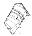
- the light shaft 21 according to the invention, which has an upper region 12 and a lower region 13.
- the light shaft is designed to be open.
- the adjoining the upper region 12 lateral surface 18 of the light shaft is semicircular.
- the light shaft according to the invention has a three-dimensional curvature, which extends in the present example into the lower region 13.
- the lateral surface 18 is surrounded on three sides by a flange 11, with which the light shaft rests against the building wall.
- the flange 11 may have a groove 6, which is located in the region of the flange on its side facing the building. This groove 6 is filled with a sealant to prevent ingress of moisture between the flange and the building wall.
- hook-shaped fastening means 5 are formed on both sides, with which the light shaft 21 is attached to the building wall. Furthermore, pockets 3 are formed in the flange on both sides, the function of which will be explained later.
- rows 2 are arranged by bulges having a plurality of teeth which form-fit with indentations, which are arranged on the essay, positively and / or non-positively co-operate, which For example in the Figures 4-6 is shown.
- an angular Stiffening 1 At the upper edge of the light shaft is an angular Stiffening 1 arranged to increase the stability of the light shaft, in particular in the upper region,
- FIG. 2 shows the attachment 22 according to the invention, which has an upper region 16 and a lower region 15.
- the upper area 16 of the tower is designed rectangular, so that rectangular light grid can be placed on him, in the lower part of the essay is designed semicircular, so that it is complementary to the semicircular shape of the upper portion of the light shaft.
- the article on flanges 23 with which the article rests against the building wall and where sealing means can be arranged.
- sealing means and their arrangement reference is made to the comments on Figure 1.
- hook-shaped fastening means 19 are formed, with which the article is attached to the building wall during the construction phase.
- pockets 3 ' are formed in the flanges, whose function will be explained later.
- the attachment in the lower region has an angle-shaped Anformung 33, which may be applied to the Anformung of the light shaft and this preferably encloses.
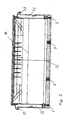
- FIG. 3 shows an interior view of the attachment according to FIG. 2.
- Four rows 7 with indentations and / or bulges can be seen from the inside, which interact positively and / or non-positively with the teeth of the light shaft.
- cams 14 can be seen from the inside, which are supported at least during the construction phase on the upper edge of the light shaft in order to initiate the possibly higher loads of the attachment during the construction phase into the light shaft.
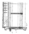
- FIG. 3a a detail of the right side of the light shaft of FIG. 3 is shown in more detail. Clearly visible are the four indentations, which are stabilized on the right side by a longitudinal web 8, so that they are statically or dynamically higher load capacity.
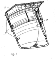
- FIG. 4 shows the set according to the invention consisting of the light shaft 21 and the attachment 22, it can be clearly seen that the attachment 22 the light shaft 21st at least partially covered.
- the attachment is arranged in its lowest position, ie the overlap between the light well 21 and attachment 22 is maximum. In this position, the pockets overlap 3 and 3 '.
- Spacers 9 are arranged both on the light well and on the attachment in order to be able to stack the sets according to the invention one above the other without wedging or damaging each other.
- the indentations and / or bulges of the attachment are positively connected to the indentations and / or bulges of the light shaft, so that in particular vertical forces exerted on the attachment are introduced into the light shaft.
- FIG. 5 shows a detail of the set according to FIG. 4.
- the form-fitting interaction between the indentations or bulges of the light shaft with the four recesses or bulges of the attachment can be clearly seen.
- a clip 20 is shown, which is arranged in the pockets 3 and 3 'and with which the set is held together during storage, transport and assembly.
- the set is mounted by the hook-shaped fastening means 5, 19 of the light shaft and the attachment are each screwed to the building wall.
- an L-shaped clamping means 10 is additionally screwed, which does not cover the flange of the attachment prior to the final assembly, as shown in Fig. 5.
- the clamping means can also at least partially cover the flange during the construction phase.
- the vertical forces occurring during the construction phase on the attachment are intercepted by the fastening means and / or introduced by the interlocking teeth of the attachment and the light shaft in the light shaft, possibly also occurring vertical forces are also transmitted from the cam 14 on the light shaft.
- the screws press the light shaft and the attachment to the building wall.
- the excavation pit can already be filled to the lower edge of the attachment.
- the screws of the attachment element are released so far that the teeth of the attachment are no longer engaged with the teeth of the light shaft in engagement.
- the attachment is then in the desired height adjusted and the teeth brought back into engagement.
- the fastener 19 is now above the screw and now no longer cooperates with the screw.
- the clamping element 10 which is screwed on in the initial assembly in a vertical position, is turned 90 ° as shown in Fig. 6 and, after re-tightening the screw, applies the required contact pressure to the wall
- the excavation pit can then be completely filled.
- ribs 4 are arranged on the light shaft, which act as a guide especially in the height adjustment of the essay.
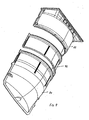
- FIG. 7 shows that the intermediate element 32 according to the invention, which has an upper region 28 and a lower region 27.
- the lateral surface of the intermediate element is designed semicircular so that it is complementary to the semicircular shape of the upper region of the light shaft.
- the intermediate element on flanges, with which the intermediate element rests against the building wall and where sealing means can be arranged.
- sealing means With regard to the sealing means and their arrangement, reference is made to the embodiment of FIG. 1.
- the intermediate element in each case angled projections 30, 29, wherein the angular Anformung 29 serves as a support on the light shaft.
- the angular Anformung 30 can cooperate with the angled Anformung 33, which is arranged in the lower region of the attachment, preferably abut it.
- FIG. 8 shows a set consisting of a light shaft 21, an intermediate element 32 and an attachment 22.
- Fig. 9 shows the set according to Fig. 8, after the parts have been joined together.
- the intermediate element 32 sits with its lower edge on the upper edge of the light shaft.
- the indentations and / or bulges of the attachment 22 are engaged with the indentations and / or bulges 31 of the intermediate element and thus guide vertical forces from the attachment into the intermediate element and from this into the light shaft.
- the assembly of the set of FIG. 9 is analogous to the assembly described with reference to FIGS. 5 and 6 with the only difference that the light shaft is extended by an intermediate element and that the attachment does not interact with the light well, but with the intermediate element.
- a preferred form of a lift-off for a grid 24 is shown.
- the lift-off consists on the one hand of the element 26, which partially cooperates positively with an undercut of the attachment and with a clip closure 25 which cooperates with a recess in the attachment 22.
- Both elements 25 and 26 are arranged on the grid. Relative to the paper plane two elements 25 and 26 are arranged on the grid.
Landscapes
- Engineering & Computer Science (AREA)
- Architecture (AREA)
- Civil Engineering (AREA)
- Structural Engineering (AREA)
- Finishing Walls (AREA)
- Connection Of Plates (AREA)
- Structures Of Non-Positive Displacement Pumps (AREA)
- Non-Portable Lighting Devices Or Systems Thereof (AREA)
- Joining Of Building Structures In Genera (AREA)
- Ladders (AREA)
Applications Claiming Priority (1)
| Application Number | Priority Date | Filing Date | Title |
|---|---|---|---|
| DE102004034654A DE102004034654A1 (de) | 2004-07-16 | 2004-07-16 | Lichtschacht mit Aufsatz |
Publications (3)
| Publication Number | Publication Date |
|---|---|
| EP1617010A2 true EP1617010A2 (fr) | 2006-01-18 |
| EP1617010A3 EP1617010A3 (fr) | 2008-02-13 |
| EP1617010B1 EP1617010B1 (fr) | 2012-01-04 |
Family
ID=35033532
Family Applications (1)
| Application Number | Title | Priority Date | Filing Date |
|---|---|---|---|
| EP05015409A Expired - Lifetime EP1617010B1 (fr) | 2004-07-16 | 2005-07-15 | Soupirail avec accessoire |
Country Status (3)
| Country | Link |
|---|---|
| EP (1) | EP1617010B1 (fr) |
| AT (1) | ATE540178T1 (fr) |
| DE (1) | DE102004034654A1 (fr) |
Cited By (5)
| Publication number | Priority date | Publication date | Assignee | Title |
|---|---|---|---|---|
| EP2857611A1 (fr) * | 2013-09-09 | 2015-04-08 | ACO Severin Ahlmann GmbH & Co. KG | Soupirail et procédé de montage d'un soupirail |
| EP3002390A3 (fr) * | 2014-09-19 | 2016-08-24 | Mauthe GmbH & Co. KG | Chapeau de soupirail |
| CN106088532A (zh) * | 2016-08-23 | 2016-11-09 | 石河子大学 | 一种成品住宅地下室采光井及其安装方法 |
| CN117308016A (zh) * | 2023-11-15 | 2023-12-29 | 中建八局发展建设有限公司 | 一种异形双曲面建筑不锈钢光筒及施工方法 |
| DE102014118831B4 (de) | 2014-01-09 | 2024-06-13 | Wolfgang Hofmann | Höhenverstellbare Straßenkappe |
Families Citing this family (4)
| Publication number | Priority date | Publication date | Assignee | Title |
|---|---|---|---|---|
| DE102011051484B4 (de) * | 2011-06-30 | 2016-03-31 | ACO Severin Ahlmann GmbH & Co Kommanditgesellschaft | Lichtschachtaufstockelement |
| DE102016105007A1 (de) | 2016-03-17 | 2017-09-21 | Pfanner Schutzbekleidung Gmbh | Kleidungsstück, insbesondere Schutzweste, und Reißverschlussanordnung |
| DE102016117895A1 (de) | 2016-09-22 | 2018-03-22 | ACO Severin Ahlmann GmbH & Co Kommanditgesellschaft | Lichtschachtkörper und Anordnung mit einem Lichtschachtkörper |
| DE102017113542B4 (de) | 2017-06-20 | 2019-05-09 | ACO Severin Ahlmann GmbH & Co Kommanditgesellschaft | Lichtschachtaufstockelement und Verfahren zur druckwasserdichten Montage eines Lichtschachtaufstockelements |
Family Cites Families (11)
| Publication number | Priority date | Publication date | Assignee | Title |
|---|---|---|---|---|
| DE7237572U (de) * | 1973-01-25 | Mauthe H | Kellerlichtschacht | |
| DE2202477C2 (de) * | 1972-01-19 | 1978-05-11 | Eberhard 7571 Varnhalt Schoeck | Unterflur-Lichtschacht fur Kellerfenster u.dgl |
| AT376473B (de) * | 1979-04-13 | 1984-11-26 | Assmann & Co | Kellerlichtschacht |
| US4704828A (en) * | 1986-08-11 | 1987-11-10 | Kemp Melvin T | Snap together window well |
| DE9421060U1 (de) * | 1994-07-06 | 1995-03-23 | Aco Severin Ahlmann Gmbh & Co Kg, 24768 Rendsburg | Lichtschachtanordnung |
| DE19602758C2 (de) * | 1996-01-26 | 1999-09-16 | Schoeck Bauteile Gmbh | Vorrichtung zur Befestigung eines Kellerlichtschachtes |
| AT404151B (de) * | 1996-08-30 | 1998-09-25 | Pichler Alois | Höhenverstellbarer schachtabschluss |
| DE29720927U1 (de) * | 1997-11-26 | 1998-01-15 | Contec Bauwerksabdichtungen GmbH, 32130 Enger | An der Außenseite einer Gebäudeseite festlegbarer Lichtschacht |
| DE20022621U1 (de) * | 2000-12-21 | 2002-02-07 | Hieber, Alexander, 86441 Zusmarshausen | Lichtschacht |
| DE20115404U1 (de) * | 2001-09-18 | 2001-11-22 | Josef Hain Gmbh & Co Kg, 83561 Ramerberg | Lichtschacht |
| US20040098929A1 (en) * | 2001-11-28 | 2004-05-27 | Kim Bronson B. | Crawl access and basement window well |
-
2004
- 2004-07-16 DE DE102004034654A patent/DE102004034654A1/de active Pending
-
2005
- 2005-07-15 EP EP05015409A patent/EP1617010B1/fr not_active Expired - Lifetime
- 2005-07-15 AT AT05015409T patent/ATE540178T1/de active
Cited By (6)
| Publication number | Priority date | Publication date | Assignee | Title |
|---|---|---|---|---|
| EP2857611A1 (fr) * | 2013-09-09 | 2015-04-08 | ACO Severin Ahlmann GmbH & Co. KG | Soupirail et procédé de montage d'un soupirail |
| RU2594182C2 (ru) * | 2013-09-09 | 2016-08-10 | Ако Зеверин Альманн Гмбх Унд Ко Коммандитгезельшафт | Система каркаса световой шахты и способ монтажа системы каркаса световой шахты |
| DE102014118831B4 (de) | 2014-01-09 | 2024-06-13 | Wolfgang Hofmann | Höhenverstellbare Straßenkappe |
| EP3002390A3 (fr) * | 2014-09-19 | 2016-08-24 | Mauthe GmbH & Co. KG | Chapeau de soupirail |
| CN106088532A (zh) * | 2016-08-23 | 2016-11-09 | 石河子大学 | 一种成品住宅地下室采光井及其安装方法 |
| CN117308016A (zh) * | 2023-11-15 | 2023-12-29 | 中建八局发展建设有限公司 | 一种异形双曲面建筑不锈钢光筒及施工方法 |
Also Published As
| Publication number | Publication date |
|---|---|
| EP1617010B1 (fr) | 2012-01-04 |
| ATE540178T1 (de) | 2012-01-15 |
| EP1617010A3 (fr) | 2008-02-13 |
| DE102004034654A1 (de) | 2006-02-16 |
Similar Documents
| Publication | Publication Date | Title |
|---|---|---|
| EP2270291B1 (fr) | Jeu de panneaux de construction avec dispositif de verrouillage de deux de ces panneaux | |
| EP2020473B1 (fr) | Clôture dotée de piquets en profilés creux métalliques et de nappes de grillages | |
| DE20017376U1 (de) | Vorrichtung zur Verbindung eines Trägers, insbesondere eines Karosserieteils eines Kraftfahrzeuges, mit einem Plattenelement, insbesondere einer Tür- oder Wandverkleidung | |
| DE102010005570A1 (de) | Profilelement zur Befestigung von Solarzellen und Solarzellenmodul | |
| DE2642227B1 (de) | Klemmelement | |
| DE202004015772U1 (de) | Dachrand-Verbinder | |
| EP1617010B1 (fr) | Soupirail avec accessoire | |
| EP2995732A1 (fr) | Caniveau de façade | |
| EP2737241B1 (fr) | Élément de fermeture pour extrémités de tubes | |
| EP0329060B1 (fr) | Dispositif porteur pour une couverture de mur ou de plafond | |
| DE202010000940U1 (de) | Profilelement zur Befestigung von Solarzellen und Solarzellenmodul | |
| EP2976938B1 (fr) | Plate-bande surelevee | |
| DE102010022845A1 (de) | Kantenschutzelement für die Anordnung ungerahmter PV-Module | |
| DE102013112912A1 (de) | Stützpfosten für eine Wand oder einen Zaun sowie Wand oder Zaun und Wand-Zaun-Kombination | |
| DE2803892A1 (de) | Bodenbelagsplatte und damit hergestellter bodenbelag | |
| WO2014037408A1 (fr) | Structure de toit plat, procédé de fabrication d'une structure de toit plat et élément de sécurité en cas de tempête | |
| DE202009010705U1 (de) | Wandsegment und Hochbeet bestehend aus Wandsegmenten | |
| DE102014106068B4 (de) | Vorrichtung zur Verbindung zweier einander gegenüberliegender plattenförmiger Schalungselemente | |
| EP3527734B1 (fr) | Caniveau d'écoulement des eaux pourvu de cadre de montage | |
| EP2327846A2 (fr) | Plaque de fond en matière synthétique | |
| EP3241954A1 (fr) | Suspente pour constructions de plafond | |
| DE102018112634A1 (de) | Fugenprofil | |
| DE102018102488A1 (de) | Anordnung zur Positionierung eines Flachteils an einem Schaltschrankrahmengestell sowie ein entsprechendes Verfahren | |
| DE202017103179U1 (de) | Oberteil eines Straßenablaufs | |
| EP3431682B1 (fr) | Profil de dilatation destiné à recevoir une tension horizontale comprenant une aile d'ancrage et une zone centrale |
Legal Events
| Date | Code | Title | Description |
|---|---|---|---|
| PUAI | Public reference made under article 153(3) epc to a published international application that has entered the european phase |
Free format text: ORIGINAL CODE: 0009012 |
|
| AK | Designated contracting states |
Kind code of ref document: A2 Designated state(s): AT BE BG CH CY CZ DE DK EE ES FI FR GB GR HU IE IS IT LI LT LU LV MC NL PL PT RO SE SI SK TR |
|
| AX | Request for extension of the european patent |
Extension state: AL BA HR MK YU |
|
| PUAL | Search report despatched |
Free format text: ORIGINAL CODE: 0009013 |
|
| AK | Designated contracting states |
Kind code of ref document: A3 Designated state(s): AT BE BG CH CY CZ DE DK EE ES FI FR GB GR HU IE IS IT LI LT LU LV MC NL PL PT RO SE SI SK TR |
|
| AX | Request for extension of the european patent |
Extension state: AL BA HR MK YU |
|
| 17P | Request for examination filed |
Effective date: 20080331 |
|
| 17Q | First examination report despatched |
Effective date: 20080530 |
|
| AKX | Designation fees paid |
Designated state(s): AT BE BG CH CY CZ DE DK EE ES FI FR GB GR HU IE IS IT LI LT LU LV MC NL PL PT RO SE SI SK TR |
|
| GRAP | Despatch of communication of intention to grant a patent |
Free format text: ORIGINAL CODE: EPIDOSNIGR1 |
|
| GRAS | Grant fee paid |
Free format text: ORIGINAL CODE: EPIDOSNIGR3 |
|
| GRAA | (expected) grant |
Free format text: ORIGINAL CODE: 0009210 |
|
| RAP1 | Party data changed (applicant data changed or rights of an application transferred) |
Owner name: MEA BAUSYSTEME GMBH |
|
| AK | Designated contracting states |
Kind code of ref document: B1 Designated state(s): AT BE BG CH CY CZ DE DK EE ES FI FR GB GR HU IE IS IT LI LT LU LV MC NL PL PT RO SE SI SK TR |
|
| REG | Reference to a national code |
Ref country code: GB Ref legal event code: FG4D Free format text: NOT ENGLISH |
|
| REG | Reference to a national code |
Ref country code: CH Ref legal event code: EP |
|
| REG | Reference to a national code |
Ref country code: AT Ref legal event code: REF Ref document number: 540178 Country of ref document: AT Kind code of ref document: T Effective date: 20120115 |
|
| REG | Reference to a national code |
Ref country code: IE Ref legal event code: FG4D |
|
| REG | Reference to a national code |
Ref country code: DE Ref legal event code: R096 Ref document number: 502005012284 Country of ref document: DE Effective date: 20120308 |
|
| REG | Reference to a national code |
Ref country code: NL Ref legal event code: VDEP Effective date: 20120104 |
|
| PG25 | Lapsed in a contracting state [announced via postgrant information from national office to epo] |
Ref country code: SI Free format text: LAPSE BECAUSE OF FAILURE TO SUBMIT A TRANSLATION OF THE DESCRIPTION OR TO PAY THE FEE WITHIN THE PRESCRIBED TIME-LIMIT Effective date: 20120104 |
|
| LTIE | Lt: invalidation of european patent or patent extension |
Effective date: 20120104 |
|
| PG25 | Lapsed in a contracting state [announced via postgrant information from national office to epo] |
Ref country code: BG Free format text: LAPSE BECAUSE OF FAILURE TO SUBMIT A TRANSLATION OF THE DESCRIPTION OR TO PAY THE FEE WITHIN THE PRESCRIBED TIME-LIMIT Effective date: 20120404 Ref country code: IS Free format text: LAPSE BECAUSE OF FAILURE TO SUBMIT A TRANSLATION OF THE DESCRIPTION OR TO PAY THE FEE WITHIN THE PRESCRIBED TIME-LIMIT Effective date: 20120504 Ref country code: NL Free format text: LAPSE BECAUSE OF FAILURE TO SUBMIT A TRANSLATION OF THE DESCRIPTION OR TO PAY THE FEE WITHIN THE PRESCRIBED TIME-LIMIT Effective date: 20120104 Ref country code: LT Free format text: LAPSE BECAUSE OF FAILURE TO SUBMIT A TRANSLATION OF THE DESCRIPTION OR TO PAY THE FEE WITHIN THE PRESCRIBED TIME-LIMIT Effective date: 20120104 |
|
| REG | Reference to a national code |
Ref country code: IE Ref legal event code: FD4D |
|
| PG25 | Lapsed in a contracting state [announced via postgrant information from national office to epo] |
Ref country code: FI Free format text: LAPSE BECAUSE OF FAILURE TO SUBMIT A TRANSLATION OF THE DESCRIPTION OR TO PAY THE FEE WITHIN THE PRESCRIBED TIME-LIMIT Effective date: 20120104 Ref country code: LV Free format text: LAPSE BECAUSE OF FAILURE TO SUBMIT A TRANSLATION OF THE DESCRIPTION OR TO PAY THE FEE WITHIN THE PRESCRIBED TIME-LIMIT Effective date: 20120104 Ref country code: GR Free format text: LAPSE BECAUSE OF FAILURE TO SUBMIT A TRANSLATION OF THE DESCRIPTION OR TO PAY THE FEE WITHIN THE PRESCRIBED TIME-LIMIT Effective date: 20120405 Ref country code: PT Free format text: LAPSE BECAUSE OF FAILURE TO SUBMIT A TRANSLATION OF THE DESCRIPTION OR TO PAY THE FEE WITHIN THE PRESCRIBED TIME-LIMIT Effective date: 20120504 Ref country code: PL Free format text: LAPSE BECAUSE OF FAILURE TO SUBMIT A TRANSLATION OF THE DESCRIPTION OR TO PAY THE FEE WITHIN THE PRESCRIBED TIME-LIMIT Effective date: 20120104 |
|
| PG25 | Lapsed in a contracting state [announced via postgrant information from national office to epo] |
Ref country code: CY Free format text: LAPSE BECAUSE OF FAILURE TO SUBMIT A TRANSLATION OF THE DESCRIPTION OR TO PAY THE FEE WITHIN THE PRESCRIBED TIME-LIMIT Effective date: 20120104 |
|
| PG25 | Lapsed in a contracting state [announced via postgrant information from national office to epo] |
Ref country code: DK Free format text: LAPSE BECAUSE OF FAILURE TO SUBMIT A TRANSLATION OF THE DESCRIPTION OR TO PAY THE FEE WITHIN THE PRESCRIBED TIME-LIMIT Effective date: 20120104 Ref country code: CZ Free format text: LAPSE BECAUSE OF FAILURE TO SUBMIT A TRANSLATION OF THE DESCRIPTION OR TO PAY THE FEE WITHIN THE PRESCRIBED TIME-LIMIT Effective date: 20120104 Ref country code: RO Free format text: LAPSE BECAUSE OF FAILURE TO SUBMIT A TRANSLATION OF THE DESCRIPTION OR TO PAY THE FEE WITHIN THE PRESCRIBED TIME-LIMIT Effective date: 20120104 Ref country code: EE Free format text: LAPSE BECAUSE OF FAILURE TO SUBMIT A TRANSLATION OF THE DESCRIPTION OR TO PAY THE FEE WITHIN THE PRESCRIBED TIME-LIMIT Effective date: 20120104 Ref country code: SE Free format text: LAPSE BECAUSE OF FAILURE TO SUBMIT A TRANSLATION OF THE DESCRIPTION OR TO PAY THE FEE WITHIN THE PRESCRIBED TIME-LIMIT Effective date: 20120104 Ref country code: IE Free format text: LAPSE BECAUSE OF FAILURE TO SUBMIT A TRANSLATION OF THE DESCRIPTION OR TO PAY THE FEE WITHIN THE PRESCRIBED TIME-LIMIT Effective date: 20120104 |
|
| PLBE | No opposition filed within time limit |
Free format text: ORIGINAL CODE: 0009261 |
|
| STAA | Information on the status of an ep patent application or granted ep patent |
Free format text: STATUS: NO OPPOSITION FILED WITHIN TIME LIMIT |
|
| PG25 | Lapsed in a contracting state [announced via postgrant information from national office to epo] |
Ref country code: SK Free format text: LAPSE BECAUSE OF FAILURE TO SUBMIT A TRANSLATION OF THE DESCRIPTION OR TO PAY THE FEE WITHIN THE PRESCRIBED TIME-LIMIT Effective date: 20120104 |
|
| 26N | No opposition filed |
Effective date: 20121005 |
|
| REG | Reference to a national code |
Ref country code: DE Ref legal event code: R097 Ref document number: 502005012284 Country of ref document: DE Effective date: 20121005 |
|
| PG25 | Lapsed in a contracting state [announced via postgrant information from national office to epo] |
Ref country code: MC Free format text: LAPSE BECAUSE OF NON-PAYMENT OF DUE FEES Effective date: 20120731 |
|
| REG | Reference to a national code |
Ref country code: CH Ref legal event code: PL |
|
| GBPC | Gb: european patent ceased through non-payment of renewal fee |
Effective date: 20120715 |
|
| PG25 | Lapsed in a contracting state [announced via postgrant information from national office to epo] |
Ref country code: ES Free format text: LAPSE BECAUSE OF FAILURE TO SUBMIT A TRANSLATION OF THE DESCRIPTION OR TO PAY THE FEE WITHIN THE PRESCRIBED TIME-LIMIT Effective date: 20120415 Ref country code: GB Free format text: LAPSE BECAUSE OF NON-PAYMENT OF DUE FEES Effective date: 20120715 Ref country code: CH Free format text: LAPSE BECAUSE OF NON-PAYMENT OF DUE FEES Effective date: 20120731 Ref country code: LI Free format text: LAPSE BECAUSE OF NON-PAYMENT OF DUE FEES Effective date: 20120731 |
|
| PG25 | Lapsed in a contracting state [announced via postgrant information from national office to epo] |
Ref country code: TR Free format text: LAPSE BECAUSE OF FAILURE TO SUBMIT A TRANSLATION OF THE DESCRIPTION OR TO PAY THE FEE WITHIN THE PRESCRIBED TIME-LIMIT Effective date: 20120104 |
|
| PG25 | Lapsed in a contracting state [announced via postgrant information from national office to epo] |
Ref country code: LU Free format text: LAPSE BECAUSE OF NON-PAYMENT OF DUE FEES Effective date: 20120715 |
|
| PG25 | Lapsed in a contracting state [announced via postgrant information from national office to epo] |
Ref country code: HU Free format text: LAPSE BECAUSE OF FAILURE TO SUBMIT A TRANSLATION OF THE DESCRIPTION OR TO PAY THE FEE WITHIN THE PRESCRIBED TIME-LIMIT Effective date: 20050715 |
|
| REG | Reference to a national code |
Ref country code: FR Ref legal event code: PLFP Year of fee payment: 12 |
|
| REG | Reference to a national code |
Ref country code: FR Ref legal event code: PLFP Year of fee payment: 13 |
|
| REG | Reference to a national code |
Ref country code: FR Ref legal event code: PLFP Year of fee payment: 14 |
|
| PGFP | Annual fee paid to national office [announced via postgrant information from national office to epo] |
Ref country code: DE Payment date: 20240719 Year of fee payment: 20 |
|
| PGFP | Annual fee paid to national office [announced via postgrant information from national office to epo] |
Ref country code: BE Payment date: 20240722 Year of fee payment: 20 |
|
| PGFP | Annual fee paid to national office [announced via postgrant information from national office to epo] |
Ref country code: FR Payment date: 20240724 Year of fee payment: 20 |
|
| PGFP | Annual fee paid to national office [announced via postgrant information from national office to epo] |
Ref country code: AT Payment date: 20240718 Year of fee payment: 20 |
|
| PGFP | Annual fee paid to national office [announced via postgrant information from national office to epo] |
Ref country code: IT Payment date: 20240731 Year of fee payment: 20 |
|
| REG | Reference to a national code |
Ref country code: DE Ref legal event code: R071 Ref document number: 502005012284 Country of ref document: DE |
|
| REG | Reference to a national code |
Ref country code: BE Ref legal event code: MK Effective date: 20250715 |
|
| REG | Reference to a national code |
Ref country code: AT Ref legal event code: MK07 Ref document number: 540178 Country of ref document: AT Kind code of ref document: T Effective date: 20250715 |