EP2327846A2 - Plaque de fond en matière synthétique - Google Patents
Plaque de fond en matière synthétique Download PDFInfo
- Publication number
- EP2327846A2 EP2327846A2 EP10008665A EP10008665A EP2327846A2 EP 2327846 A2 EP2327846 A2 EP 2327846A2 EP 10008665 A EP10008665 A EP 10008665A EP 10008665 A EP10008665 A EP 10008665A EP 2327846 A2 EP2327846 A2 EP 2327846A2
- Authority
- EP
- European Patent Office
- Prior art keywords
- hooks
- base plate
- longitudinal sides
- ribs
- recesses
- Prior art date
- Legal status (The legal status is an assumption and is not a legal conclusion. Google has not performed a legal analysis and makes no representation as to the accuracy of the status listed.)
- Withdrawn
Links
- 229920003023 plastic Polymers 0.000 title claims abstract description 8
- 239000004033 plastic Substances 0.000 title claims abstract description 8
- 238000004519 manufacturing process Methods 0.000 claims abstract description 3
- 238000001746 injection moulding Methods 0.000 claims description 2
- 238000000034 method Methods 0.000 abstract description 2
- 230000007704 transition Effects 0.000 description 6
- -1 Polypropylen Polymers 0.000 description 4
- 239000000463 material Substances 0.000 description 2
- 229920000573 polyethylene Polymers 0.000 description 2
- 229920001155 polypropylene Polymers 0.000 description 2
- 229920000915 polyvinyl chloride Polymers 0.000 description 2
- 239000002689 soil Substances 0.000 description 2
- 239000004698 Polyethylene Substances 0.000 description 1
- 239000004743 Polypropylene Substances 0.000 description 1
- 239000000853 adhesive Substances 0.000 description 1
- 230000001070 adhesive effect Effects 0.000 description 1
- 230000001427 coherent effect Effects 0.000 description 1
- 238000003780 insertion Methods 0.000 description 1
- 230000037431 insertion Effects 0.000 description 1
- 238000009434 installation Methods 0.000 description 1
- 239000007788 liquid Substances 0.000 description 1
- 230000000149 penetrating effect Effects 0.000 description 1
- 230000002093 peripheral effect Effects 0.000 description 1
- 229920000642 polymer Polymers 0.000 description 1
- 239000004800 polyvinyl chloride Substances 0.000 description 1
- 238000004904 shortening Methods 0.000 description 1
- 239000007787 solid Substances 0.000 description 1
Images


Classifications
-
- E—FIXED CONSTRUCTIONS
- E04—BUILDING
- E04F—FINISHING WORK ON BUILDINGS, e.g. STAIRS, FLOORS
- E04F15/00—Flooring
- E04F15/02—Flooring or floor layers composed of a number of similar elements
- E04F15/10—Flooring or floor layers composed of a number of similar elements of other materials, e.g. fibrous or chipped materials, organic plastics, magnesite tiles, hardboard, or with a top layer of other materials
- E04F15/105—Flooring or floor layers composed of a number of similar elements of other materials, e.g. fibrous or chipped materials, organic plastics, magnesite tiles, hardboard, or with a top layer of other materials of organic plastics with or without reinforcements or filling materials
-
- B—PERFORMING OPERATIONS; TRANSPORTING
- B29—WORKING OF PLASTICS; WORKING OF SUBSTANCES IN A PLASTIC STATE IN GENERAL
- B29C—SHAPING OR JOINING OF PLASTICS; SHAPING OF MATERIAL IN A PLASTIC STATE, NOT OTHERWISE PROVIDED FOR; AFTER-TREATMENT OF THE SHAPED PRODUCTS, e.g. REPAIRING
- B29C45/00—Injection moulding, i.e. forcing the required volume of moulding material through a nozzle into a closed mould; Apparatus therefor
- B29C45/17—Component parts, details or accessories; Auxiliary operations
- B29C45/26—Moulds
- B29C45/2628—Moulds with mould parts forming holes in or through the moulded article, e.g. for bearing cages
-
- B—PERFORMING OPERATIONS; TRANSPORTING
- B29—WORKING OF PLASTICS; WORKING OF SUBSTANCES IN A PLASTIC STATE IN GENERAL
- B29C—SHAPING OR JOINING OF PLASTICS; SHAPING OF MATERIAL IN A PLASTIC STATE, NOT OTHERWISE PROVIDED FOR; AFTER-TREATMENT OF THE SHAPED PRODUCTS, e.g. REPAIRING
- B29C45/00—Injection moulding, i.e. forcing the required volume of moulding material through a nozzle into a closed mould; Apparatus therefor
- B29C45/17—Component parts, details or accessories; Auxiliary operations
- B29C45/26—Moulds
- B29C45/2673—Moulds with exchangeable mould parts, e.g. cassette moulds
-
- E—FIXED CONSTRUCTIONS
- E01—CONSTRUCTION OF ROADS, RAILWAYS, OR BRIDGES
- E01C—CONSTRUCTION OF, OR SURFACES FOR, ROADS, SPORTS GROUNDS, OR THE LIKE; MACHINES OR AUXILIARY TOOLS FOR CONSTRUCTION OR REPAIR
- E01C5/00—Pavings made of prefabricated single units
- E01C5/20—Pavings made of prefabricated single units made of units of plastics, e.g. concrete with plastics, linoleum
-
- E—FIXED CONSTRUCTIONS
- E04—BUILDING
- E04F—FINISHING WORK ON BUILDINGS, e.g. STAIRS, FLOORS
- E04F15/00—Flooring
- E04F15/02—Flooring or floor layers composed of a number of similar elements
- E04F15/02194—Flooring consisting of a number of elements carried by a non-rollable common support plate or grid
-
- B—PERFORMING OPERATIONS; TRANSPORTING
- B29—WORKING OF PLASTICS; WORKING OF SUBSTANCES IN A PLASTIC STATE IN GENERAL
- B29L—INDEXING SCHEME ASSOCIATED WITH SUBCLASS B29C, RELATING TO PARTICULAR ARTICLES
- B29L2031/00—Other particular articles
- B29L2031/10—Building elements, e.g. bricks, blocks, tiles, panels, posts, beams
- B29L2031/104—Tiles
-
- E—FIXED CONSTRUCTIONS
- E01—CONSTRUCTION OF ROADS, RAILWAYS, OR BRIDGES
- E01C—CONSTRUCTION OF, OR SURFACES FOR, ROADS, SPORTS GROUNDS, OR THE LIKE; MACHINES OR AUXILIARY TOOLS FOR CONSTRUCTION OR REPAIR
- E01C2201/00—Paving elements
- E01C2201/12—Paving elements vertically interlocking
-
- E—FIXED CONSTRUCTIONS
- E01—CONSTRUCTION OF ROADS, RAILWAYS, OR BRIDGES
- E01C—CONSTRUCTION OF, OR SURFACES FOR, ROADS, SPORTS GROUNDS, OR THE LIKE; MACHINES OR AUXILIARY TOOLS FOR CONSTRUCTION OR REPAIR
- E01C2201/00—Paving elements
- E01C2201/20—Drainage details
-
- E—FIXED CONSTRUCTIONS
- E01—CONSTRUCTION OF ROADS, RAILWAYS, OR BRIDGES
- E01C—CONSTRUCTION OF, OR SURFACES FOR, ROADS, SPORTS GROUNDS, OR THE LIKE; MACHINES OR AUXILIARY TOOLS FOR CONSTRUCTION OR REPAIR
- E01C2201/00—Paving elements
- E01C2201/20—Drainage details
- E01C2201/202—Horizontal drainage channels
- E01C2201/207—Horizontal drainage channels channels on the bottom
-
- E—FIXED CONSTRUCTIONS
- E04—BUILDING
- E04F—FINISHING WORK ON BUILDINGS, e.g. STAIRS, FLOORS
- E04F2201/00—Joining sheets or plates or panels
- E04F2201/01—Joining sheets, plates or panels with edges in abutting relationship
- E04F2201/0153—Joining sheets, plates or panels with edges in abutting relationship by rotating the sheets, plates or panels around an axis which is parallel to the abutting edges, possibly combined with a sliding movement
Definitions
- the present invention relates to a square plastic bottom plate having the features of the preamble of claim 1.
- Plastic floor panels are known as floor coverings for various applications.
- the present invention relates to floor slabs which can be connected to one another by a connecting system, so that the overall result is a coherent floor covering which does not form a gap between the individual floor slabs even when the floor is laid without adhesive. It should be the same with each other to a floor assembled floor panels.
- U.S. Patent 4,226,064 shows, for example, a system of floor panels with edge-side connecting elements, which consist of hooks and recesses and which engage in the vertical direction with each other.
- the adjacent panels are connected to each other both horizontally and vertically. It is therefore possible to lay on green areas or other unpaved subsoil, without the connections to read due to changing loads.
- the hooks are seconded to two opposite longitudinal sides and the recesses on the other two, also opposite longitudinal sides, and because the hooks have rounded surface elements with a radius whose center is in the region of the adjacent longitudinal side of the plate, the rounded hooks of a plate to be laid can be guided with a pivoting movement under an already lying plate and there engage in the compatible recesses.
- the laying is so flexible, so that additional plates can be placed both with the receptacles on the hook of the already lying plate, as well as with their hooks under the recesses of an already laid plate can grip.
- a particularly robust embodiment provides that the hooks are chamfered at their outer sides facing the corners of the bottom plate, such that the width of the hooks is reduced from the longitudinal side towards a free end of the hook.
- the bottom plate may be provided for stiffening the bottom plate that run below the top between the longitudinal sides of ribs extending in height from the top to a lower edge.
- the load capacity is further improved if between the ribs diagonal ribs are arranged, which have a smaller extent in the direction perpendicular to the surface than the ribs. additionally can be provided that the ribs limit square fields, meet in the centers of the diagonal ribs in each case a sleeve.
- the sleeves are open towards the top of the bottom plate so that rainwater can run off.
- the base body can be produced in an injection molding process, wherein the sleeves are formed by exchangeable pins which form the sleeves open to the surface in a first embodiment with long pins, while in a first embodiment with short pins the sleeves are formed closed to the surface. This reduces the tooling costs.
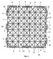
- FIG. 1 an embodiment of a plastic base plate according to the invention is shown in a view from the bottom.
- the bottom plate is in her
- the first longitudinal sides 1 are opposite, as are the second longitudinal sides 2.
- the longitudinal sides 1 each carry three fastening elements which protrude beyond the cross section of the longitudinal sides bounded by the longitudinal sides 1 and 2 addition.
- the fastening elements comprise on each longitudinal side 1 a central hook 3 and two lateral hooks 4.
- the longitudinal sides 2 have pocket-shaped recesses compatible with the hooks 3 and 4.
- Each longitudinal side 2 has a central recess 5 and two lateral recesses 6.
- the base plate is so far axisymmetric to a first axis of symmetry 7, which extends centrally through the longitudinal sides 1, and to a second axis of symmetry 8, which passes through the longitudinal sides 2 in the middle and parallel to the longitudinal sides 1.
- the two axes of symmetry 7 and 8 meet in the geometric center of the bottom plate.
- the two hooks 3 and the recesses 5 compatible therewith are in each case arranged centrally on the longitudinal side which carries them, and consequently are formed symmetrically with respect to the respective symmetry axes 7 and 8.
- the side hooks 4 are provided with rounded outsides 10 located on the sides of the hooks facing the corner areas of the bottom panel. The exact design of the hooks 3 and 4 and the pockets 5 and 6 will be described below with reference to enlarged representations.
- the underside of the bottom plate is further formed with a square rib structure 11.
- the individual ribs extend parallel and in a uniformly distributed distance to each other between the sides 1 and 2.
- the ribs 11 define smaller square fields of the base of the bottom plate. These fields are in turn stiffened by diagonal ribs 12.
- the diagonal ribs 12 reinforce the individual quadratic surface elements located between the ribs 11 opposite one of the upper side of the ribs 11 Base plate acting on punctual pressure load.
- At the center of each individual square surface element that is to say at the point of intersection of the intersecting diagonal ribs 12, is in each case a sleeve element 13 which is connected to the diagonal ribs 12.
- the sleeve member 13 also serves to stiffen the diagonal ribs 12 and thus the overlying, supported by the diagonal ribs 12 surface element.
- the sleeve members 13 may be formed depending on the embodiment as a tubular member with a central blind hole, or have a through hole. In the first case, the surface of the bottom plate is closed, in the second case, it has drainage holes, which can discharge liquid from the top through the open sleeve members 13.
- FIG. 2 shows the bottom plate FIG. 1 in an end view in a partial cross-section along the axis of symmetry 7 from FIG. 1 , The view corresponds to the top view of the in FIG. 1 Longitudinal side located above 2. Same components bear the same reference numerals.
- the ribs 11 extend from an upper side 14 of the base plate to a common lower plane, which in operation represents the bearing surface on the ground.
- the diagonal ribs 12 rise from the top 14 only over about 20% of the height of the ribs 11 and protrude into the space bounded by the ribs 11 interior.
- a lower edge 15 of the ribs 11 further has a U-shaped recess 16, which allows in the operating position the passage from an interior to the adjacent interior space between the ribs 11. For example, penetrating rainwater can spread and drain away.
- the hooks 3 and 4 have in this representation a visible, approximately quarter-circular configuration, wherein the top is concave rounded with a smaller radius, while the bottom is convexly curved with a larger radius.
- the Top is attached approximately halfway up the outside of the longitudinal wall 1, while the underside of the hooks 3 and 4 begins at the level of the lower edge 15 of the longitudinal wall 1.
- the hooks 3 and 4 taper from the point of attachment to the longitudinal wall 1 to a free end 17 back.
- the free end 17 has almost vertically upwards.
- FIG. 3 illustrates the described design of the bottom plate in perspective form. Shown in the FIG. 3 top left a perspective view of the underside of a corner area, as well as in the FIG. 3 bottom right, a perspective top view of the top of a corner region of the bottom plate described. The same components in turn bear the same reference numerals.
- the hook 4 is provided on its side facing away from the hook 3, which faces the corner region of the bottom plate, provided with an inclined side 10.
- the side 10 is not parallel to the three ribs 20 which stiffen the hook 4. It runs much more starting from the longitudinal side 1 obliquely to the next adjacent rib 20 and ends at a small distance from this.
- the hook 4 is shortened in its longitudinal extent parallel to the longitudinal side 1 at its free end 17 with respect to the centrally arranged hook 3. This shortening of the hook 4 allows a mounting of a bottom plate in a particularly simple manner.
- FIG. 4 shows a hook 4 in a greatly enlarged cross-sectional view.
- the rib 20 which is the shape of the hook, is set below the middle in the lower half of the longitudinal side 1.
- a lower side 21 extends at a radius to the free upper edge 17 of the hook, wherein the radius has approximately a center, which is denoted by 22.
- An upper surface 23 is also curved in a circular arc and has geometrically about a midpoint at 24.
- a horizontal transition region 25 is provided between the surface 23 and the side wall 1.
- a vertical transition region 26 is provided between the surface 23 and the upper edge 17.
- FIG. 5 shows the one to the hook FIG. 4 Compatible recess 6.
- the recess 6 is limited by a rear wall 27 and the surface 14 of the bottom plate.
- a downwardly pointing undercut 28 is formed on the side wall 2.
- An inner surface 29 of the undercut 28 initially extends approximately perpendicularly from the longitudinal wall 2 to the rear wall 27 and then merges into a bevel 30 in a radius.
- a vertical transition region 31 which ultimately leads to the back of the surface 14, which is designated 32.
- the surface 32, the surface 31 and the slope 30 results in a recess into which the free area of the hook 4 with the upper edge 17, the arcuate radius 21, the vertical surface 27 and the upper surface 23 flush fits.
- the design of the hook 4 with the taper in the oblique face 10 also allows the insertion of a plate between three already lying plates.
- the two longitudinal sides of the free space each have the hook facing the free space, while the trapped by the longitudinal sides of the free space has recesses .
- the missing plate can now be hooked with the hooks 3 and 4 in the transverse side, being introduced at an angle of about 45 ° to the horizontal to the transverse side until the hooks 3 and 4 engage under the recesses 5 and 6.
- the longitudinal hooks of the already laid plates point upwards to the newly added plate.
- the hooks 3 and 4 engage in their recesses 5 and 6 and hold the new plate so firmly.
- the lowering of the new plate on the hook is made possible by the fact that the hook 4 is tapered at its corner-facing end face 10. This taper allows the pivoting movement described above.
- a toothing of the plates in the surface results from the fact that adjacent plates are always rotated by 90 ° to each other, so that alternate along a line of the floor hooks and recesses. A lifting of the soil along a line, as it can occur in conventional soils, is therefore excluded.
Landscapes
- Engineering & Computer Science (AREA)
- Architecture (AREA)
- Civil Engineering (AREA)
- Structural Engineering (AREA)
- Manufacturing & Machinery (AREA)
- Mechanical Engineering (AREA)
- Floor Finish (AREA)
- Rigid Containers With Two Or More Constituent Elements (AREA)
Applications Claiming Priority (1)
| Application Number | Priority Date | Filing Date | Title |
|---|---|---|---|
| DE102009056079A DE102009056079A1 (de) | 2009-11-30 | 2009-11-30 | Kunststoff-Bodenplatte |
Publications (2)
| Publication Number | Publication Date |
|---|---|
| EP2327846A2 true EP2327846A2 (fr) | 2011-06-01 |
| EP2327846A3 EP2327846A3 (fr) | 2012-07-18 |
Family
ID=43734245
Family Applications (1)
| Application Number | Title | Priority Date | Filing Date |
|---|---|---|---|
| EP10008665A Withdrawn EP2327846A3 (fr) | 2009-11-30 | 2010-08-19 | Plaque de fond en matière synthétique |
Country Status (2)
| Country | Link |
|---|---|
| EP (1) | EP2327846A3 (fr) |
| DE (1) | DE102009056079A1 (fr) |
Cited By (4)
| Publication number | Priority date | Publication date | Assignee | Title |
|---|---|---|---|---|
| EP2657401A1 (fr) * | 2012-04-26 | 2013-10-30 | Daniel Broghammer | Plaque de montage |
| CN104631770A (zh) * | 2015-02-06 | 2015-05-20 | 蔡燕明 | 具有改良稳定结构的塑胶地板 |
| DE202023102817U1 (de) | 2023-05-22 | 2023-09-28 | Kurt Stumpf | Bodenplatte |
| US20260015871A1 (en) * | 2024-07-11 | 2026-01-15 | Sur-Loc Holdings, LLC | Flooring system with interlocking panel assemblies |
Families Citing this family (1)
| Publication number | Priority date | Publication date | Assignee | Title |
|---|---|---|---|---|
| DE102016118380A1 (de) * | 2016-09-28 | 2018-03-29 | Guido Schulte | Bodenbelag sowie Verfahren zum Verlegen des Bodenbelages |
Citations (3)
| Publication number | Priority date | Publication date | Assignee | Title |
|---|---|---|---|---|
| US4018025A (en) | 1975-11-28 | 1977-04-19 | Pawling Rubber Corporation | Ventilated interlocking floor tile |
| US4226064A (en) | 1977-02-02 | 1980-10-07 | Hans Kraayenhof | Flooring comprising adjoining plastics elements |
| CA2233485A1 (fr) | 1997-04-02 | 1998-10-02 | Nigel Mandel | Tuile a emboitement a assemblage rapide |
Family Cites Families (6)
| Publication number | Priority date | Publication date | Assignee | Title |
|---|---|---|---|---|
| US5616389A (en) * | 1995-10-30 | 1997-04-01 | Blatz; Warren J. | Surface covering tile |
| JPH1161719A (ja) * | 1997-08-19 | 1999-03-05 | Miyagawa Kasei Ind Co Ltd | 敷板の連結構造 |
| DE10158215B4 (de) * | 2001-11-28 | 2007-02-01 | Meyer, Hans | Verlegesystem für Bodenplatten |
| DE102004008130B3 (de) * | 2004-02-18 | 2005-09-15 | Purus Arzberg Gmbh | Verlegeplatte |
| WO2007006151A1 (fr) * | 2005-07-07 | 2007-01-18 | Ouellet Andre | Carreau de pont à lame de soutien |
| JP2008280767A (ja) * | 2007-05-11 | 2008-11-20 | Suminoe Textile Co Ltd | フリーアクセスフロアパネル |
-
2009
- 2009-11-30 DE DE102009056079A patent/DE102009056079A1/de not_active Ceased
-
2010
- 2010-08-19 EP EP10008665A patent/EP2327846A3/fr not_active Withdrawn
Patent Citations (3)
| Publication number | Priority date | Publication date | Assignee | Title |
|---|---|---|---|---|
| US4018025A (en) | 1975-11-28 | 1977-04-19 | Pawling Rubber Corporation | Ventilated interlocking floor tile |
| US4226064A (en) | 1977-02-02 | 1980-10-07 | Hans Kraayenhof | Flooring comprising adjoining plastics elements |
| CA2233485A1 (fr) | 1997-04-02 | 1998-10-02 | Nigel Mandel | Tuile a emboitement a assemblage rapide |
Cited By (4)
| Publication number | Priority date | Publication date | Assignee | Title |
|---|---|---|---|---|
| EP2657401A1 (fr) * | 2012-04-26 | 2013-10-30 | Daniel Broghammer | Plaque de montage |
| CN104631770A (zh) * | 2015-02-06 | 2015-05-20 | 蔡燕明 | 具有改良稳定结构的塑胶地板 |
| DE202023102817U1 (de) | 2023-05-22 | 2023-09-28 | Kurt Stumpf | Bodenplatte |
| US20260015871A1 (en) * | 2024-07-11 | 2026-01-15 | Sur-Loc Holdings, LLC | Flooring system with interlocking panel assemblies |
Also Published As
| Publication number | Publication date |
|---|---|
| DE102009056079A1 (de) | 2011-06-01 |
| EP2327846A3 (fr) | 2012-07-18 |
Similar Documents
| Publication | Publication Date | Title |
|---|---|---|
| EP1294995B1 (fr) | Système de plancher comprenant un pluralité de planches de plancher identiques | |
| EP1223265A2 (fr) | Panneau de parquet | |
| DE60314459T2 (de) | Bauelement für die mantelbetonbauweise | |
| DE2007129A1 (de) | Estrichplatte mit einem Überzug | |
| DE60101794T2 (de) | Zusatzvorrichtung für ein modularelement für hohlräume und bodenstrukturen | |
| DE3815140C2 (de) | Blendrahmen zur Bildung einer Fugenschalung zwecks Verbindung von einzelnen Glasbauelementen | |
| DE2803892A1 (de) | Bodenbelagsplatte und damit hergestellter bodenbelag | |
| DE102009056079A1 (de) | Kunststoff-Bodenplatte | |
| DE102009004915A1 (de) | Rigolensystem mit wenigstens einer Versickerbox | |
| DE10043609C1 (de) | Mauerwerk | |
| DE102008053230B4 (de) | Einrichtung zum Verbinden von Bauplatten, insbesondere Bodenpaneelen | |
| DE102014106068B4 (de) | Vorrichtung zur Verbindung zweier einander gegenüberliegender plattenförmiger Schalungselemente | |
| EP1197611A1 (fr) | Dalle pour plancher démontable | |
| DE202023102817U1 (de) | Bodenplatte | |
| DE202024104862U1 (de) | Entwässerungsrinne zum Ableiten von Oberflächenwasser | |
| EP0960985A2 (fr) | Poutrelle en I pour constructions en bâtiment | |
| DE3837564C2 (de) | Hohlraumboden | |
| DE19640128A1 (de) | Bodenbelag-Element | |
| DE102022104203A1 (de) | Doppelbodensystem | |
| AT12475U1 (de) | Vorrichtung zur überbrückung einer dehnungsfuge | |
| DE3909803C2 (de) | Industriefußboden aus Betonplatten | |
| EP3431682B1 (fr) | Profil de dilatation destiné à recevoir une tension horizontale comprenant une aile d'ancrage et une zone centrale | |
| EP3375935A1 (fr) | Pavé en pierre doublé | |
| EP3865641A1 (fr) | Dispositif de raccordement permettant de raccorder des planches ou des panneaux à des supports | |
| DE4422226A1 (de) | System von Wandelementen |
Legal Events
| Date | Code | Title | Description |
|---|---|---|---|
| PUAI | Public reference made under article 153(3) epc to a published international application that has entered the european phase |
Free format text: ORIGINAL CODE: 0009012 |
|
| AK | Designated contracting states |
Kind code of ref document: A2 Designated state(s): AL AT BE BG CH CY CZ DE DK EE ES FI FR GB GR HR HU IE IS IT LI LT LU LV MC MK MT NL NO PL PT RO SE SI SK SM TR |
|
| AX | Request for extension of the european patent |
Extension state: BA ME RS |
|
| PUAL | Search report despatched |
Free format text: ORIGINAL CODE: 0009013 |
|
| AK | Designated contracting states |
Kind code of ref document: A3 Designated state(s): AL AT BE BG CH CY CZ DE DK EE ES FI FR GB GR HR HU IE IS IT LI LT LU LV MC MK MT NL NO PL PT RO SE SI SK SM TR |
|
| AX | Request for extension of the european patent |
Extension state: BA ME RS |
|
| RIC1 | Information provided on ipc code assigned before grant |
Ipc: E01C 5/20 20060101ALI20120614BHEP Ipc: B29C 45/26 20060101ALI20120614BHEP Ipc: B29L 31/10 20060101ALI20120614BHEP Ipc: E04F 15/10 20060101AFI20120614BHEP |
|
| STAA | Information on the status of an ep patent application or granted ep patent |
Free format text: STATUS: THE APPLICATION IS DEEMED TO BE WITHDRAWN |
|
| 18D | Application deemed to be withdrawn |
Effective date: 20130119 |