EP1617232A2 - Système d'imagerie radio et méthode associée - Google Patents
Système d'imagerie radio et méthode associée Download PDFInfo
- Publication number
- EP1617232A2 EP1617232A2 EP05014901A EP05014901A EP1617232A2 EP 1617232 A2 EP1617232 A2 EP 1617232A2 EP 05014901 A EP05014901 A EP 05014901A EP 05014901 A EP05014901 A EP 05014901A EP 1617232 A2 EP1617232 A2 EP 1617232A2
- Authority
- EP
- European Patent Office
- Prior art keywords
- sub
- array
- antenna
- signal
- profiles
- Prior art date
- Legal status (The legal status is an assumption and is not a legal conclusion. Google has not performed a legal analysis and makes no representation as to the accuracy of the status listed.)
- Granted
Links
Images


Classifications
-
- H—ELECTRICITY
- H01—ELECTRIC ELEMENTS
- H01Q—ANTENNAS, i.e. RADIO AERIALS
- H01Q21/00—Antenna arrays or systems
-
- H—ELECTRICITY
- H01—ELECTRIC ELEMENTS
- H01Q—ANTENNAS, i.e. RADIO AERIALS
- H01Q21/00—Antenna arrays or systems
- H01Q21/06—Arrays of individually energised antenna units similarly polarised and spaced apart
-
- H—ELECTRICITY
- H01—ELECTRIC ELEMENTS
- H01Q—ANTENNAS, i.e. RADIO AERIALS
- H01Q13/00—Waveguide horns or mouths; Slot antennas; Leaky-waveguide antennas; Equivalent structures causing radiation along the transmission path of a guided wave
- H01Q13/08—Radiating ends of two-conductor microwave transmission lines, e.g. of coaxial lines, of microstrip lines
Definitions
- the present invention relates to a radiometer imaging system and method thereof capable of reducing the number of antenna elements arranged therein while improving a resolution of an image considerably.
- Interferometric synthetic aperture radiometers have been developed to obtain a high angular resolution using a static array of small antennas, avoiding the scanning of the large size antenna required by real aperture radiometer.
- An imaging system using a synthetic aperture radiometer reconstructs an image by receiving a radiant energy naturally emitted from an object on the ground in a micrometer-wave or a millimeter-wave band via an antenna array.
- the structure of the antenna array is an important fact that determines acquisition efficiency for image.
- the antenna array employed in the radiometer imaging system has a pattern in which an overall arrangement is in a Y-type, a ⁇ - type or a T-type.
- the Y-type antenna array is capable of obtaining a narrow width of synthetic aperture beamwidth and a wide range of alias free FOV (Field Of View).
- a number of antenna elements are required to obtain a high resolution image. For example, 130 or more antenna elements are needed to obtain a synthetic aperture beamwidth of about 1°.
- the structure of an overall antenna array becomes complicated, and an operation calculation for obtaining correlations between signals received from each pairs of the antenna elements becomes difficult, which results in an increase of power consumption and a demand for a large-scale system.
- an object of the present invention to provide a radiometer imaging system and method, capable of reducing the number of antenna elements employed therein while improving a resolution of an image.
- a radiometer imaging system comprising an antenna array including a number of sub-arrays arranged to form a Y-type configuration, wherein each sub-array is formed of a plurality of antenna elements arranged in a predetermined pattern, each antenna element being responsive to a radiant wave corresponding to a radiant energy emitted from an object; and imaging means for requisiting an image of the object using a signal received from each antenna element in the antenna array.
- an method of requisiting an image in a radiometer imaging system including an antenna array and a receiver array, wherein the antenna array including a number of sub-arrays arranged to form a Y-type configuration, each sub-array being formed of a plurality of antenna elements arranged in a sub-Y-type, each antenna element being responsive to a radiant wave corresponding to a radiant energy emitted from an object, the receiver array having the same number of receivers as the antenna elements, each receiver being associated with one of the antenna elements in a one-to-one correspondence to thereby define a channel, for generating a first signal having a predetermined band extracted from an output of each antenna element and a second signal having a phase difference of 90 degrees from the first signal, the method comprising the steps of: (a) calculating a pixel map coordinate by using position information of the antenna elements in the antenna array; (b) measuring correlations for channel pairs; (c) mapping the correlations correspondingly to the pixel
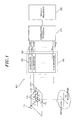
- Fig. 1 is a block diagram of a radiometer imaging system 100 in accordance with the present invention
- Fig. 2 shows a detailed diagram of the antenna array shown in Fig. 1.
- the radiometer imaging system 100 includes an antenna array 110, a receiver array 150, a correlation processor 170 and an imaging processor 180.
- the antenna array 110 has a number of antenna elements 111.
- Each of the antenna elements 111 may be formed of a known antenna type, for example, microsrtip antenna and waveguide antenna, which is capable of receiving a millimeter- or a micrometer-wave band signal.
- the antenna elements 111 transmit the received signals to the receiver array 150.
- the receiver array 150 has the same number of receivers 151 as that of the antenna elements, each corresponding to one of the antenna elements 111 in a one-to-one correspondence, to thereby define a channel between an antenna element and a receiver.
- a plurality of antenna elements 111 forms a single sub-array 113, and a multiplicity of sub-arrays 113 are arranged in a radial direction about their central position while maintaining a predetermined angular interval therebetween, thus forming a Y-type configuration.
- the sub-arrays 113 are radially disposed with respect to the central position by an angular interval of 120 degrees.
- Such antenna array 110 can be formed by arranging the antenna elements 111 on an object on which an antenna is to be installed or on a base substrate in the above-described Y-type pattern.
- the antenna array 110 includes a multiplicity of sub-arrays 113, each being formed of a plurality of, e.g., four antenna elements 111 arranged in a Y-type configuration.
- the Y-type configuration formed by a plurality of antenna elements within each sub-array will be referred to as a sub-Y-type as contrast as the Y-type pattern formed by a multiplicity of the sub-arrays.
- sub-arrays 113 joint to form a single sub-array group, and thus formed sub-array groups are categorized into a central sub-array group 115a disposed at a central portion of the antenna array 110 and a plurality of branch sub-array groups 115b disposed in the Y-type pattern of the same angular interval of 120 degrees about the central sub-array group 115a.
- the central sub-array group 115a has four sub-arrays 113 while each branch sub-array group 115b has two sub-arrays 113.
- the grouping of the sub-arrays is intended to extend the arm of sub-Y-type array keeping a complete sampling on a principle axes.
- each sub-array 113 may have a shape other than the Y-shape shown in Fig. 2.
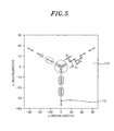
- each sub-array 113 can have a T-type, a ⁇ (delta)-type or a linear pattern, respectively and a number of sub-arrays 113 are radially arranged about a central position by an angular interval of 120 degrees, to thereby form a Y-shape as a whole in each of the drawings.
- each sub-array 113 illustrated in Figs. 4 and 5 are formed of three antenna elements other than that of Fig. 3.
- reference numeral d1 represents an interval between antenna elements 111
- reference numeral d2 represents an interval between the sub-arrays 113
- reference numeral d3 represents an interval between the sub-array groups 115a and 115b.
- the interval d1 between unit antennas 111 in a single sub-array 113 is determined depending on a desired alias free FOV.
- the interval d1 is set to be shorter than a central wavelength ⁇ but not smaller than 0.5 times the central wavelength ⁇ (that is, 0.5 ⁇ ⁇ d1 ⁇ ).
- the interval d2 between the sub-arrays 113 and the interval d3 between the sub-array groups 115 are determined to be 4d1 ⁇ d2 ⁇ 8d1 by considering a desired synthetic aperture beamwidth and a principal beam efficiency.
- the reduction rate R of the beamwidth is varied depending on the interval d3. Accordingly, the interval d3 needs to be determined based on a desired reduction rate R of the beamwidth.
- the principal beam efficiency can also be varied depending on the interval d3 between the sub-array groups 115a and 115b. That is to say, the principal beam efficiency decreases sharply when the interval d3 becomes greater than eight times the interval d1. Therefore, it is preferred to set the interval d3 to be not greater than eight (-twenty) times the interval d1 (i.e., d3 ⁇ 8d1 ( ⁇ 20d1).
- the principal beam efficiency refers to a ratio of energy by a principal beam to an entire energy that arrives at an antenna.
- the principal beam represents a beam of a direction in which a maximum energy is emitted from the antenna.
- the receiver array 150 includes a first to an k-th (where 'k' represents a positive integer) receivers, each being connected to one of the antenna elements 111 in a one-to-one on a corresponding channel.
- 'k' represents a positive integer
- All of the receivers 151, 152,... have same components, and each serves to extract a signal having a predetermined band from the output provided from a corresponding one of the antenna elements 111 to generate a first signal I and a second signal Q.
- the first signal I is an in phase signal while the second signal Q is a quadrature phase signal which is phase-delayed by 90 degrees from the first signal I.
- Fig. 8 shows detailed block diagram of the receiver array 150 and the correlation processor 170 shown in Fig. 1, wherein the drawing describes a correlation process with the two receivers 151 and 152 in order to help the understanding of the correlation calculation mechanism while avoiding complexity of the drawing.
- the receivers 151 and 152 include low-noise amplifiers 121 and 141; bandpass filters 123 and 143; mixers 125 and 145; IF (Intermediate Frequency) filters 127 and 147; I/Q demodulators 129 and 149; and local oscillators 131 and 133, respectively.
- the local oscillators 131 and 133 the two receivers 151 and 152 share them. Alternatively, it is possible for each receiver to have separate local oscillators.
- the low-noise amplifiers 121 and 141 amplify by a predetermined gain the signals received from their respective corresponding antenna elements 111, respectively.
- the bandpass filters 123 and 143 allow only signals having a predetermined band to pass therethrough among the amplified signals from the low-noise amplifiers 121 and 141, respectively.
- the mixers 125 and 145 mix the signals from the bandpass filters 123 and 143 with signals oscillated by the local oscillators 153 and 154 to down-convert the mixed signals into signals with a predetermined frequency band, respectively.
- the IF filters 127 and 147 allow only the down-converted signals with predetermined intermediate frequency band from the mixers 125 and 145 to pass therethrough, respectively.
- the I/Q demodulators 129 and 149 demodulates the outputs from the IF filters 127 and 147 to produce first signals I 1 , I 2 and second signals Q 1 , Q 2 , respectively.
- the first signals I 1 , I 2 are in phase signals while the second signals Q 1 , Q 2 have a phase difference of 90 degrees from the first signals I 1 , I 2 , respectively.
- the correlation processor 170 calculates correlation (Sn,m) between two correlated channels m and n (n ⁇ m) by using the first signals I 1 , I 2 and the second signals Q 1 , Q 2 outputted from the two correlated channel pairs.
- n and m represent channel numbers for the receivers in the receiver array 150, respectively.
- E[.] represents a mean value
- m an n denote correlated channel pairs
- In and I m indicate first signals from correlated channel pairs, respectively
- Q n and Q m indicate second signals from correlated channel pair, respectively
- j represents an imaginary number portion of a complex number.
- the correlation processor 170 calculates correlations for all of correlated receiver pairs.
- Such a correlation processor 170 includes an A/D converter 171, first to fourth multiplication average calculators 172 to 175, first and second adders 176 and 177, and low pass filters (LPFs) 178 and 179.
- the A/D converter 171 converts the first signals I 1 , I 2 and the second signals Q 1 , Q 2 from the receivers 151 and 152 into digital signals.
- the first multiplication average calculator 172 multiplies a first signal I 1 from the first receiver 151 and a first signal I 2 from the second receiver 152 and then calculates a mean value thereof, E [I 1 ⁇ I 2 ].
- the second multiplication average calculator 173 multiplies a second signal Q 1 from the first receiver 151 and a second signal Q 2 from the second receiver 152 and then calculates a mean value thereof, E[Q 1 ⁇ Q 2 ].
- the third multiplication average calculator 174 multiplies the first signal Q 1 from the first receiver 151 and the second signal I 2 from the second receiver 152 and then calculates a mean value thereof, E[Q 1 xI 2] .
- the fourth multiplication average calculator 175 multiplies the first signal I 1 from the first receiver 151 and the second signal Q 2 of the second receiver 152 and then calculates a mean value thereof, E[I 1 xQ 2 ].
- the first adder 176 adds the outputs from the first and the second multiplication average calculators 172 and 173 to produce an added signal ⁇ r .
- the added signal ⁇ r from the first adder 176 indicates the real number portion of the correlation (Sn,m), namely, E[I n ⁇ I m ] + E[Q n ⁇ Q m ].
- the second adder 177 subtracts the output of the fourth multiplication average calculator 175 from the output of the third multiplication average calculator 174 to produce a subtracted signal ⁇ i .
- the signal ⁇ i produced by the second adder 177 indicates an imaginary number portion of the correlation (Sn,m), namely, ⁇ E[Q 1 ⁇ I 2] - E[I 1 ⁇ Q 2 ] ⁇ .
- the low pass filters 178 and 179 serve to pass only the signals of low frequency band among the signals from the first and the second adders 178 and 179.
- the imaging processor 180 generates a 2D image by using the correlations of channel pairs provided from the correlation processor 170.
- pixel map (visibility coverage) coordinates are obtained by using position information of the antenna elements 111 by the correlation processor 170 in the antenna array 110, to thereby detect 2-D pixel data which will then be stored, wherein the pixel map coordinates reflect the correlations of antenna element pairs.
- Fig. 11 shows pixel map coordinates obtained with respect to the antenna elements 111 in the antenna array 110 shown in Fig. 2.
- the 2-D pixel data are correspondingly mapped to the correlations (Sn,m) for the channel pairs (m, n) measured by the correlation processor 170.
- a 1-D FFT Fast Fourier Transformation
- the first direction of the pixel map coordinate is any one of a u-direction and a v-direction which are perpendicular to with each other.
- the u-direction is defined as a first pixel map coordinate direction in spatial frequency domain while the v-direction is defined as a second pixel map coordinate direction in spatial frequency domain.
- a 1-D FFT is also performed on the first 1-D profiles P ⁇ using values on a first main-axis, to thereby obtain first 1-D main-axis component profiles P ⁇ 0 which are not influenced by the Alias effect among the first 1-D profiles P ⁇ , where zero('0') represents a main-axis.
- the main-axis refers to a coordinate axis in which no alias component is generated, and, in Fig. 12, is marked as a term 'alias free profile'.
- a main-axis refers to each branch direction serving as a center axis with respect to remaining axes.
- the main-axis is defined as a vertically upright axis among the axes shown in Fig. 12.
- the first 1-D profiles P ⁇ are corrected using the 1-D main-axis component profiles P 0 , to thereby obtain first corrected 1-D profiles P ⁇ in which alias components are removed with respect to the first direction (u) of the pixel map coordinate in spatial frequency domain.
- the corrected 1-D profiles P ⁇ are subjected to an inverse FFT (IFFT), to thereby recover 2-D pixel data.
- the 2-D pixel data are first recovered 2-D data to which values corrected to correspond to the pixel map coordinates in Fig. 11 are applied.
- a 1-D FFT is performed on the values extracted along the second pixel map coordinate direction v perpendicular to the first pixel map coordinate direction u with respect to the first recovered 2-D pixel data, to thereby generate a second 1-D profile P ⁇ (at step 270).
- a 1-D FFT is also performed on the second 1-D profiles P ⁇ using values along the second main-axis, to thereby obtain second 1-D main-axis profiles P ⁇ 0 , which are not influenced by the alias effect among the second 1-D profiles P ⁇ .
- the second main-axis is defined as a diagonal axis with respect to the first main-axis in Fig. 12.
- the second 1-D profiles P ⁇ 0 are corrected using the second 1-D main-axis component profile P ⁇ 0 while applying the weighting function as expressed in Eq. 3, to thereby produce second corrected profiles P ⁇ in which alias components are removed with respect to the second direction (v) of the pixel map coordinates in spatial frequency domain.
- the second corrected pixel data is a 2-D pixel signal obtained by removing alias components in both u and v directions.
- a weight is applied on the second corrected pixel data without having alias components, to thereby produce a corrected image signal.
- a weighting can be accomplished by using various known methods: for example, by using a rectangular window, a hamming window, a hanning window, a gaussian window, etc. Alternatively, the weighting may be omitted.
- a 2-D FFT is performed on the corrected image signal, to thereby obtain a desired 2-D image for the object at step 320, and the 2-D image is displayed on a display element at step 330.
- Figs. 13 and 14 show experiment results of imaging performance of the novel imaging system and the conventional imaging system, respectively.
- Fig. 13 is a unit pixel image obtained by using an antenna array in which 40 antenna elements are arranged in the sub Y-type configuration as shown in Fig. 2, wherein a central frequency, a bandwidth, a measurement distance and a measurement time are set to be 37 GHz, 100 MHz, 4 M and 0.65 ⁇ s , respectively.
- Fig. 14 is a unit pixel image obtained by using an antenna array in which 52 antenna elements are arranged in a conventional Y-type, wherein a central frequency, a bandwidth, a measurement distance and a measurement time are set to be 37 GHz, 100 MHz, 4 M and 0.65 ⁇ s , respectively, as in Fig. 13.
- the novel imaging system can generate a unit pixel image of a size identical to that of a unit pixel image obtained by the conventional imaging system even though using 12 less antenna elements. Consequently, with the reduced number of antenna elements, a greatly improved pixel resolution can be obtained in accordance with the present invention.
Landscapes
- Variable-Direction Aerials And Aerial Arrays (AREA)
- Radiation Pyrometers (AREA)
Applications Claiming Priority (1)
| Application Number | Priority Date | Filing Date | Title |
|---|---|---|---|
| KR1020040052878A KR100613491B1 (ko) | 2004-07-08 | 2004-07-08 | 안테나 배열 구조체 및 이를 적용한 라디오미터 영상획득 시스템 및 방법 |
Publications (3)
| Publication Number | Publication Date |
|---|---|
| EP1617232A2 true EP1617232A2 (fr) | 2006-01-18 |
| EP1617232A3 EP1617232A3 (fr) | 2006-02-08 |
| EP1617232B1 EP1617232B1 (fr) | 2013-12-11 |
Family
ID=35240928
Family Applications (1)
| Application Number | Title | Priority Date | Filing Date |
|---|---|---|---|
| EP05014901.2A Expired - Lifetime EP1617232B1 (fr) | 2004-07-08 | 2005-07-08 | Système d'imagerie radio et méthode associée |
Country Status (3)
| Country | Link |
|---|---|
| US (1) | US7402794B2 (fr) |
| EP (1) | EP1617232B1 (fr) |
| KR (1) | KR100613491B1 (fr) |
Cited By (1)
| Publication number | Priority date | Publication date | Assignee | Title |
|---|---|---|---|---|
| CN111538000A (zh) * | 2020-03-30 | 2020-08-14 | 西南电子技术研究所(中国电子科技集团公司第十研究所) | 均匀圆阵列综合孔径辐射计亮温反演成像方法 |
Families Citing this family (6)
| Publication number | Priority date | Publication date | Assignee | Title |
|---|---|---|---|---|
| JP2007256171A (ja) * | 2006-03-24 | 2007-10-04 | Nec Corp | ミリ波画像処理装置及びミリ波画像処理方法 |
| US8295418B2 (en) * | 2007-03-15 | 2012-10-23 | Qualcomm Incorporated | Adjacent channel interference detection for wireless communication |
| US9354317B2 (en) * | 2014-04-09 | 2016-05-31 | Raytheon Company | Simultaneous forward and inverse synthetic aperture imaging LADAR |
| KR101947905B1 (ko) | 2017-06-08 | 2019-04-30 | 국방과학연구소 | 이미지 신호대역을 이용한 라디오미터 감도 향상 장치 |
| JP7210178B2 (ja) * | 2018-07-23 | 2023-01-23 | 株式会社東芝 | 受信システム、レーダシステム及び信号処理方法 |
| US12309327B2 (en) * | 2021-02-24 | 2025-05-20 | General Electric Company | Automated beam scan calibration, alignment, and adjustment |
Family Cites Families (5)
| Publication number | Priority date | Publication date | Assignee | Title |
|---|---|---|---|---|
| FR2775146B1 (fr) * | 1998-02-18 | 2000-03-31 | Agence Spatiale Europeenne | Systeme radiometrique hyperfrequence interferometrique a balayage mecanique |
| FR2788133B1 (fr) | 1998-12-30 | 2003-05-02 | Agence Spatiale Europeenne | Systeme radiometrique comprenant une antenne du type a synthese d'ouverture et son application en imagerie hyperfrequence |
| FR2812128B1 (fr) * | 2000-07-24 | 2003-01-10 | Agence Spatiale Europeenne | Procede et dispositif pour commander un radiometre interferometrique |
| US6593876B2 (en) * | 2000-08-11 | 2003-07-15 | The Seti League Inc. | Adaptive microwave antenna array |
| US6842157B2 (en) | 2001-07-23 | 2005-01-11 | Harris Corporation | Antenna arrays formed of spiral sub-array lattices |
-
2004
- 2004-07-08 KR KR1020040052878A patent/KR100613491B1/ko not_active Expired - Fee Related
-
2005
- 2005-07-08 EP EP05014901.2A patent/EP1617232B1/fr not_active Expired - Lifetime
- 2005-07-08 US US11/176,242 patent/US7402794B2/en not_active Expired - Fee Related
Non-Patent Citations (1)
| Title |
|---|
| NAPIER ET AL.: "The Very Large Array: Design and Performance of a Modern Synthesis Radio Telescope", PROCEEDINGS OF THE IEEE, vol. 71, November 1983 (1983-11-01), pages 1295 - 1320 |
Cited By (1)
| Publication number | Priority date | Publication date | Assignee | Title |
|---|---|---|---|---|
| CN111538000A (zh) * | 2020-03-30 | 2020-08-14 | 西南电子技术研究所(中国电子科技集团公司第十研究所) | 均匀圆阵列综合孔径辐射计亮温反演成像方法 |
Also Published As
| Publication number | Publication date |
|---|---|
| KR20060004041A (ko) | 2006-01-12 |
| EP1617232B1 (fr) | 2013-12-11 |
| EP1617232A3 (fr) | 2006-02-08 |
| US20070018089A1 (en) | 2007-01-25 |
| KR100613491B1 (ko) | 2006-08-21 |
| US7402794B2 (en) | 2008-07-22 |
Similar Documents
| Publication | Publication Date | Title |
|---|---|---|
| Hurley-Walker et al. | GaLactic and Extragalactic All-sky Murchison Widefield Array (GLEAM) survey–I. A low-frequency extragalactic catalogue | |
| Bock et al. | SUMSS: a wide-field radio imaging survey of the southern sky. I. Science goals, survey design, and instrumentation | |
| Wijnholds et al. | Calibration challenges for future radio telescopes | |
| EP0395863B1 (fr) | Radiomètre à ouverture synthétisée utilisant une technique numérique de concentration du faisceau | |
| US4996533A (en) | Single station radar ocean surface current mapper | |
| CA2266275C (fr) | Chercheur de direction des signaux et dispositif pour le traitement des donnees provenant dudit chercheur | |
| CN113687317A (zh) | 一种基于综合积分的宽带相控阵雷达天线极化校准方法 | |
| RU2368917C1 (ru) | Способ формирования изображений в многоканальных ртлс и рлс | |
| CN106646529A (zh) | 一种基于多波束优选的gnss天线阵抗干扰方法 | |
| CN110703219A (zh) | 一种多发多收近场直线阵列获取目标远场rcs的方法 | |
| EP1617232B1 (fr) | Système d'imagerie radio et méthode associée | |
| JP2005127874A (ja) | 偏波合成開口レーダ較正方法及び装置 | |
| Goodberlet | Improved image reconstruction techniques for synthetic aperture radiometers | |
| CN113985410A (zh) | 一种综合孔径辐射计的近岸误差抑制方法 | |
| RU2379705C2 (ru) | Способ двухэтапного восстановления изображений в многоканальных радиолокационных и радиотеплолокационных станциях | |
| CN110542880A (zh) | 一种频点部分交叠条件下的doa估计策略 | |
| Camps et al. | Angular and radiometric resolution of Y-shaped nonuniform synthetic aperture radiometers for earth observation | |
| JP2002107440A (ja) | 方向検出方法及び方向検出装置 | |
| Sukumar | Ooty synthesis radio telescope-Design and performance | |
| Gething | Analysis of multicomponent wavefields | |
| DE102011077186B4 (de) | Vorrichtung und Verfahren zum Schätzen des Signals in einem Kommunikationssystem | |
| Li et al. | Extreme high wind speed monitoring with spatial resolution enhancement of HY-2B SMR brightness temperature | |
| Wijnholds et al. | Hemispheric imaging of galactic neutral hydrogen with a phased array antenna system | |
| CN115902792B (zh) | 基于法拉第旋转估计的高轨sar时变电离层效应误差校正方法 | |
| CN111538001A (zh) | 三维天线阵综合孔径辐射计快速亮温反演方法 |
Legal Events
| Date | Code | Title | Description |
|---|---|---|---|
| PUAI | Public reference made under article 153(3) epc to a published international application that has entered the european phase |
Free format text: ORIGINAL CODE: 0009012 |
|
| PUAL | Search report despatched |
Free format text: ORIGINAL CODE: 0009013 |
|
| AK | Designated contracting states |
Kind code of ref document: A2 Designated state(s): AT BE BG CH CY CZ DE DK EE ES FI FR GB GR HU IE IS IT LI LT LU LV MC NL PL PT RO SE SI SK TR |
|
| AX | Request for extension of the european patent |
Extension state: AL BA HR MK YU |
|
| AK | Designated contracting states |
Kind code of ref document: A3 Designated state(s): AT BE BG CH CY CZ DE DK EE ES FI FR GB GR HU IE IS IT LI LT LU LV MC NL PL PT RO SE SI SK TR |
|
| AX | Request for extension of the european patent |
Extension state: AL BA HR MK YU |
|
| 17P | Request for examination filed |
Effective date: 20060808 |
|
| AKX | Designation fees paid |
Designated state(s): DE FR GB IT NL |
|
| 17Q | First examination report despatched |
Effective date: 20080721 |
|
| R17C | First examination report despatched (corrected) |
Effective date: 20080721 |
|
| GRAP | Despatch of communication of intention to grant a patent |
Free format text: ORIGINAL CODE: EPIDOSNIGR1 |
|
| INTG | Intention to grant announced |
Effective date: 20130621 |
|
| RIN1 | Information on inventor provided before grant (corrected) |
Inventor name: KANG, GM SIL Inventor name: KIM, YONG HOON Inventor name: KIM, SUNG HYUN Inventor name: CHOI, JUN HO |
|
| GRAS | Grant fee paid |
Free format text: ORIGINAL CODE: EPIDOSNIGR3 |
|
| GRAA | (expected) grant |
Free format text: ORIGINAL CODE: 0009210 |
|
| AK | Designated contracting states |
Kind code of ref document: B1 Designated state(s): DE FR GB IT NL |
|
| REG | Reference to a national code |
Ref country code: GB Ref legal event code: FG4D |
|
| REG | Reference to a national code |
Ref country code: DE Ref legal event code: R096 Ref document number: 602005042092 Country of ref document: DE Effective date: 20140206 |
|
| REG | Reference to a national code |
Ref country code: NL Ref legal event code: VDEP Effective date: 20131211 |
|
| PG25 | Lapsed in a contracting state [announced via postgrant information from national office to epo] |
Ref country code: NL Free format text: LAPSE BECAUSE OF FAILURE TO SUBMIT A TRANSLATION OF THE DESCRIPTION OR TO PAY THE FEE WITHIN THE PRESCRIBED TIME-LIMIT Effective date: 20131211 |
|
| REG | Reference to a national code |
Ref country code: DE Ref legal event code: R097 Ref document number: 602005042092 Country of ref document: DE |
|
| PLBE | No opposition filed within time limit |
Free format text: ORIGINAL CODE: 0009261 |
|
| STAA | Information on the status of an ep patent application or granted ep patent |
Free format text: STATUS: NO OPPOSITION FILED WITHIN TIME LIMIT |
|
| 26N | No opposition filed |
Effective date: 20140912 |
|
| REG | Reference to a national code |
Ref country code: DE Ref legal event code: R097 Ref document number: 602005042092 Country of ref document: DE Effective date: 20140912 |
|
| REG | Reference to a national code |
Ref country code: FR Ref legal event code: PLFP Year of fee payment: 11 |
|
| PGFP | Annual fee paid to national office [announced via postgrant information from national office to epo] |
Ref country code: GB Payment date: 20150714 Year of fee payment: 11 Ref country code: DE Payment date: 20150713 Year of fee payment: 11 |
|
| PGFP | Annual fee paid to national office [announced via postgrant information from national office to epo] |
Ref country code: FR Payment date: 20150713 Year of fee payment: 11 |
|
| PG25 | Lapsed in a contracting state [announced via postgrant information from national office to epo] |
Ref country code: IT Free format text: LAPSE BECAUSE OF FAILURE TO SUBMIT A TRANSLATION OF THE DESCRIPTION OR TO PAY THE FEE WITHIN THE PRESCRIBED TIME-LIMIT Effective date: 20131211 |
|
| REG | Reference to a national code |
Ref country code: DE Ref legal event code: R119 Ref document number: 602005042092 Country of ref document: DE |
|
| GBPC | Gb: european patent ceased through non-payment of renewal fee |
Effective date: 20160708 |
|
| PG25 | Lapsed in a contracting state [announced via postgrant information from national office to epo] |
Ref country code: FR Free format text: LAPSE BECAUSE OF NON-PAYMENT OF DUE FEES Effective date: 20160801 Ref country code: DE Free format text: LAPSE BECAUSE OF NON-PAYMENT OF DUE FEES Effective date: 20170201 |
|
| REG | Reference to a national code |
Ref country code: FR Ref legal event code: ST Effective date: 20170331 |
|
| PG25 | Lapsed in a contracting state [announced via postgrant information from national office to epo] |
Ref country code: GB Free format text: LAPSE BECAUSE OF NON-PAYMENT OF DUE FEES Effective date: 20160708 |