EP1618326B1 - Luftsparender schieber - Google Patents
Luftsparender schieber Download PDFInfo
- Publication number
- EP1618326B1 EP1618326B1 EP04751281A EP04751281A EP1618326B1 EP 1618326 B1 EP1618326 B1 EP 1618326B1 EP 04751281 A EP04751281 A EP 04751281A EP 04751281 A EP04751281 A EP 04751281A EP 1618326 B1 EP1618326 B1 EP 1618326B1
- Authority
- EP
- European Patent Office
- Prior art keywords
- slide block
- slide
- outer body
- gas
- port
- Prior art date
- Legal status (The legal status is an assumption and is not a legal conclusion. Google has not performed a legal analysis and makes no representation as to the accuracy of the status listed.)
- Expired - Lifetime
Links
- 230000001105 regulatory effect Effects 0.000 claims abstract description 4
- 239000012530 fluid Substances 0.000 claims description 16
- 238000004891 communication Methods 0.000 claims description 3
- 230000001276 controlling effect Effects 0.000 claims 1
- 239000007789 gas Substances 0.000 description 29
- 238000000034 method Methods 0.000 description 13
- 230000008569 process Effects 0.000 description 10
- IJGRMHOSHXDMSA-UHFFFAOYSA-N Atomic nitrogen Chemical compound N#N IJGRMHOSHXDMSA-UHFFFAOYSA-N 0.000 description 8
- 239000002912 waste gas Substances 0.000 description 7
- 238000013022 venting Methods 0.000 description 6
- QVGXLLKOCUKJST-UHFFFAOYSA-N atomic oxygen Chemical compound [O] QVGXLLKOCUKJST-UHFFFAOYSA-N 0.000 description 5
- 239000001301 oxygen Substances 0.000 description 5
- 229910052760 oxygen Inorganic materials 0.000 description 5
- 229910052757 nitrogen Inorganic materials 0.000 description 4
- 239000000047 product Substances 0.000 description 4
- 238000001179 sorption measurement Methods 0.000 description 4
- 239000002808 molecular sieve Substances 0.000 description 3
- 238000000926 separation method Methods 0.000 description 3
- URGAHOPLAPQHLN-UHFFFAOYSA-N sodium aluminosilicate Chemical compound [Na+].[Al+3].[O-][Si]([O-])=O.[O-][Si]([O-])=O URGAHOPLAPQHLN-UHFFFAOYSA-N 0.000 description 3
- 239000002699 waste material Substances 0.000 description 3
- 230000008859 change Effects 0.000 description 2
- 230000000875 corresponding effect Effects 0.000 description 2
- 230000013011 mating Effects 0.000 description 2
- 230000009467 reduction Effects 0.000 description 2
- 239000006227 byproduct Substances 0.000 description 1
- 230000001143 conditioned effect Effects 0.000 description 1
- 238000010276 construction Methods 0.000 description 1
- 230000002079 cooperative effect Effects 0.000 description 1
- 238000005516 engineering process Methods 0.000 description 1
- 239000011261 inert gas Substances 0.000 description 1
- 239000000463 material Substances 0.000 description 1
- 230000002441 reversible effect Effects 0.000 description 1
- 238000012163 sequencing technique Methods 0.000 description 1
- 239000007787 solid Substances 0.000 description 1
- 230000007704 transition Effects 0.000 description 1
Images


Classifications
-
- F—MECHANICAL ENGINEERING; LIGHTING; HEATING; WEAPONS; BLASTING
- F16—ENGINEERING ELEMENTS AND UNITS; GENERAL MEASURES FOR PRODUCING AND MAINTAINING EFFECTIVE FUNCTIONING OF MACHINES OR INSTALLATIONS; THERMAL INSULATION IN GENERAL
- F16K—VALVES; TAPS; COCKS; ACTUATING-FLOATS; DEVICES FOR VENTING OR AERATING
- F16K11/00—Multiple-way valves, e.g. mixing valves; Pipe fittings incorporating such valves
- F16K11/02—Multiple-way valves, e.g. mixing valves; Pipe fittings incorporating such valves with all movable sealing faces moving as one unit
- F16K11/06—Multiple-way valves, e.g. mixing valves; Pipe fittings incorporating such valves with all movable sealing faces moving as one unit comprising only sliding valves, i.e. sliding closure elements
- F16K11/065—Multiple-way valves, e.g. mixing valves; Pipe fittings incorporating such valves with all movable sealing faces moving as one unit comprising only sliding valves, i.e. sliding closure elements with linearly sliding closure members
- F16K11/0655—Multiple-way valves, e.g. mixing valves; Pipe fittings incorporating such valves with all movable sealing faces moving as one unit comprising only sliding valves, i.e. sliding closure elements with linearly sliding closure members with flat slides
-
- Y—GENERAL TAGGING OF NEW TECHNOLOGICAL DEVELOPMENTS; GENERAL TAGGING OF CROSS-SECTIONAL TECHNOLOGIES SPANNING OVER SEVERAL SECTIONS OF THE IPC; TECHNICAL SUBJECTS COVERED BY FORMER USPC CROSS-REFERENCE ART COLLECTIONS [XRACs] AND DIGESTS
- Y10—TECHNICAL SUBJECTS COVERED BY FORMER USPC
- Y10T—TECHNICAL SUBJECTS COVERED BY FORMER US CLASSIFICATION
- Y10T137/00—Fluid handling
- Y10T137/5544—Reversing valves - regenerative furnace type
-
- Y—GENERAL TAGGING OF NEW TECHNOLOGICAL DEVELOPMENTS; GENERAL TAGGING OF CROSS-SECTIONAL TECHNOLOGIES SPANNING OVER SEVERAL SECTIONS OF THE IPC; TECHNICAL SUBJECTS COVERED BY FORMER USPC CROSS-REFERENCE ART COLLECTIONS [XRACs] AND DIGESTS
- Y10—TECHNICAL SUBJECTS COVERED BY FORMER USPC
- Y10T—TECHNICAL SUBJECTS COVERED BY FORMER US CLASSIFICATION
- Y10T137/00—Fluid handling
- Y10T137/8593—Systems
- Y10T137/86493—Multi-way valve unit
- Y10T137/86839—Four port reversing valves
Definitions
- the invention relates to the field of gas generators, and more particularly to a pressure swing adsorption apparatus.
- On Board Inert Gas Generating Systems OBIGGS
- On Board Oxygen Generating Systems OBOGS
- PSA pressure swing adsorption
- This known PSA technology uses compressed air or conditioned engine bleed air fed through a valve or valves to pressurize molecular sieve contained in one of a number of canisters. After a predetermined period of time, the valve changes state, venting the one canister full of sieve, then pressurizing the next canister. This process of pressurization and venting is the PSA process.
- Previous PSA systems have been controlled by a rotary valve, driven by a fixed or variable speed motor. Still others utilize a system of dedicated independent valves to control each pressurization and each venting cycle for each canister or bed.
- Known PSA systems have utilized a linear 4-way slide valve, which connects input air port with the first canister, while connecting a vent port with the second canister.
- the valve changes state, which connects the vent port with the first canister and simultaneously connecting the second canister with the input air.
- the linear 4-way slide valve simplifies the complex system of independent dedicated valves necessary on some systems.
- linear valve has also proven to be more reliable then either the rotary valve or the system of valves, accomplishing the same tasks.
- the linear valve used on typical PSA systems is pneumatically operated.
- Miniature pilot solenoid valves that are opened and closed using solid state electronics, housed in an EMI shielded enclosure control pilot gas.
- the pilot solenoids provide gas pressure to two gas cylinders, which are connected to a sliding block.
- the block slides across a mating plate with three openings or ports.
- the ports are constructed in a straight line.
- the outer ports are equal-distance from center port.
- the sliding block has an undercut, which acts as a flow path.
- the flow path is sized to connect two of the three ports at any one point in time.
- a controller is set to open and close the miniature pilot valves at a predetermined time.
- a typical slide type valve in form of a changeover device is known from GB-A-2-095 798 .
- the present invention utilizes a highly reliable slide valve device, which normally operates like a four-way valve.
- the device provides a new communication path for airflow, which produces the desired air reuse, or conservation, without the unnecessary complication of numerous valves.
- the reduction of parts and improving air use results in a reduction in weight which is critical to airborne applications of either oxygen or nitrogen systems.
- a slide type valve for regulating a gas generating system that has at least a first and a second gas concentrating bed unit includes an outer body with a slide face having at least three open ports communicating with an interior cavity formed in the outer body.
- the slide face has an exterior surface and an essentially flat interior surface.
- the open ports form a vent port and at least two bed ports each of which is adapted to communicate an air flow with a gas concentrating bed unit.
- the vent port is formed between two bed ports.
- a feed air port in the outer body is adapted for communicating feed air into the interior cavity of the outer body.
- a slide block having an essentially flat face suitable for sliding along the interior surface of the slide face of the outer body has a hollow interior cavity and a first and a second opening formed through the flat face compatible with the open ports of the outer body.
- the slide face of the slide block has a closing portion position between the first and second openings.
- a controller moves the slide block between a first state and a second state for desired air flow between the gas concentrating bed units, feed air port, and the vent port.
- the present invention discloses the device that performs air conservation techniques by reducing the number of valves used from 4 or more discrete valves to one valve.
- the inherent reliability of the system is improved; the overall weight of the system 10 is reduced; and, the principles of air conservation, by reusing waste gas from a PSA system 10, are efficiently put into practice.
- the device also maintains the ability for air conservation, independent of wear, due to the mechanical relation of the single slide block integral to the slide valve. Other systems, relying on numerous valves, will have a tendency to wear, and likely to change states at different times, reducing the efficiency of the air conservation system.
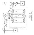
- the PSA process works by simply providing a source of clean dry air to a set of sieve filled canisters 11,12,13,14 . By alternately pressurizing one canister, and venting the second canister, the PSA process adsorbs the waste gas, allowing product to pass. At a predetermined time interval, the once pressurized canister is vented while the once vented canister is pressurized. Since the process is primarily mechanical, the process is reversible and will produce an infinite source of product, either oxygen or nitrogen as long as the system control is operational, and the source of pressurized air is available.
- Figure 2 discloses a known PSA system 10 using a 4-way slide valve.
- the valve In the first state, the valve directs feed air to bed 1, while directing waste gas external to the system.
- the valve changes state the waste gas in bed 1 is directed external to the system, and bed 2 receives the feed air.
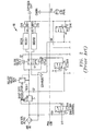
- Figure 3 teaches a known PSA system 10 using a series of independent valves, either two-way or three way valves, to perform air conservation.
- a number of the valves are used to perform the normal pressurization and venting for the PSA system.
- An additional set of valves are used to perform the pre-pressurization function.
- the present invention eliminates a number of the independent valves by combining certain two-way and three way valves. This invention eliminates all the additional valves taught in U.S. Patent No. 5,074,893 , Fluid Adsorption System, and U.S. Patent No. 6,077,331 , Molecular Sieve Type Gas Separation Apparatus and Method, by way of exemplary prior teachings, and accomplishes air conservation with two highly reliable solenoid valves or similar functioning motors, and one linear slide valve.
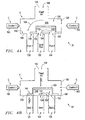
- the linear slide valve has all of the features of those described in Patent No. 6,409,807, but it includes an air conserving feature previously unknown. It has an internal slide block 100 which moves linearly back and forth across a slide plate 106 with three mating ports 130, 132, and 134 .
- the slide plate ports are labeled "port 1,” “vent port,” and “port 2" sequentially across the plate in the Figure 4a-e series.
- the feed air flow 108 passes through a fourth port labeled "feed air" 144 , and depending on the position of the slide block 100 , alternately pressurizes either port 1 130 or port 2 134 .
- port 1 130 is connected to the feed air
- port 2 134 is connected to the vent port 132 by the air or fluid path 110 provided within the interior chamber 148 in the slide block 100 . See Fig. 4a .
- port 2 134 is connected to the feed air 144
- port 1 130 is connected to the vent port 132 for fluid or gas flow 110 . See Fig. 4e .
- a slide type valve V for regulating a gas generating system 10 that has at least a first and a second gas concentrating bed unit 12 and 14 respectively includes an outer body 120 with a slide face 106 having at least three open ports 130 , 132 , and 134 communicating with an interior cavity 136 formed in the outer body 120 .
- the slide face 106 has an exterior surface 140 and an essentially flat interior surface 142 .
- the open ports form a vent port 132 and at least two bed ports 130, 134 each of which is adapted to communicate an air flow with a gas concentrating bed unit 12 or 14 .
- the vent port 132 is formed between two bed ports 130 and 134 .
- a feed air port 144 in the outer body 120 is adapted for communicating feed air 108 into the interior cavity 136 of the outer body 120 .
- a slide block 100 having an essentially flat face 146 suitable for sliding along the interior surface of the slide face 142 of the outer body 120 has a hollow interior cavity 148 and a first and a second opening 150 and 152 respectively formed through the flat face 146 compatible with the open ports of the outer body 120 .
- the slide face 146 of the slide block 100 has a closing portion 104 position between the first and second openings 150 and 152.
- a controller C moves the slide block between a first state S1 and a second state S2 for desired air flow between the gas concentrating bed units 12, 14 and the vent port 132 .
- the undercut 102 , the two ends of the slide face 146 of the slide block 100 , the closing portion 104 , and the vents 150 and 152 , are formed to permit fluid flows 108 and 110 in accordance with the following description of Figures 4a through 4e .
- the present invention has the internal slide block 100 , which has an undercut 102 for providing the vent gas path as previously described.
- an undercut 102 for providing the vent gas path as previously described.
- the slide plate ports 150, 152 and the slide block undercut 102 are changed from the known art.
- the spacing of the ports 150, 152 and the slide face 146 are critically sized and spaced with the undercut 102 of the slide block 100 .
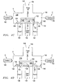
- the PSA process is allowed to continue as in a typical OBOGS or OBIGGS.
- position A corresponding to state S1 of Fig. 4a
- the feed gas or fluid flow 108 comes in the feed gas port 144 , and is directed to port 1 130 .
- port 2 134 a gas or fluid flow 110 , generally a waste by-product, is directed to the vent port 132 through the cavity 148 formed in the slide block 100 .
- the slide block 100 is moved into position such that ports 1 130 and 2134 are allowed to have fluid or gas flow communication. Fluid flow with Port 1 130 passes through vent 150 into the chamber 148 and through vent 152 into Port 2 134 or vice versa.
- This gas path 110 allows the waste gas from port 1 130 to pass to port 2 134 through the interior cavity 148 of the sliding block 100 .
- the closing feature 104 blocks the passage of gas or fluid into and out of the vent port 132 .
- the feed air flow 108 is blocked from passage into port 1 130 , vent port 132 , and port 2 134 .
- vent port 132 is opened for fluid flow to port 1 130 and is closed to port 2 134 and the feed air flow 108 .
- the feed air port 144 is opened to port 2 134 and is closed to port 1 130 and to the feed air flow 108 .
- Port 2 134 is blocked by the sliding surface 146 of the slide block 100 to any fluid flow there-through.
- Exhaust flow 110 can communicate between the port 1 130 through vent 150 then into the cavity 148 and finally through vent 152 that is partially opened to the vent port 132 , and vice versa.
- the feed gas port 144 is completely open to port 2 134 permitting fluid flow 108 from the feed air port 144 through the interior cavity 136 and into port 2 134 .
- the vent gas port 132 is completely open to port 1 130 permitting fluid to pass from port 1 130 through the cavity or chamber 148 of the slide block 100 to the vent port 132 through the openings 150 and 152 in the slide block 100.
- valve V changes state and the process is reversed, where the waste gas flow 110 from port 2 134 is allowed to pre-pressurize port 1 130 during the transition from position B to position A, or state S2 to state S1.
- Control 1 160 and control 2 162 can be solenoids selected for their operational characteristics. Such solenoids would operate in an opposing, but cooperating, manner to move the slide block 100 back and forth. Alternatively, one or more known linear drive motors can function to move the slide block 100 in the controller C , thereby replacing solenoids for control 1 160 and control 2 162.
- the present air conserving slide valve should improve the air efficiency over 15%.
Landscapes
- Engineering & Computer Science (AREA)
- General Engineering & Computer Science (AREA)
- Mechanical Engineering (AREA)
- Separation Of Gases By Adsorption (AREA)
- Multiple-Way Valves (AREA)
- Sliding Valves (AREA)
- Magnetically Actuated Valves (AREA)
- Fluid-Damping Devices (AREA)
- Massaging Devices (AREA)
- Chair Legs, Seat Parts, And Backrests (AREA)
Claims (10)
- Schiebeventil zum Regulieren eines Gaserzeugungssystems (10), das wenigstens eine erste und eine zweite Gaskonzentrations-Betteinheit (12, 14) besitzt, wobei das Schiebeventil versehen ist mit:einem äußeren Körper (120), der eine Gleitfläche (106) besitzt, die mit wenigstens vier offenen Anschlüssen (130, 132, 134 und 144) versehen ist, die mit einem in dem Außenkörper (120) ausgebildeten Innenhohlraum (136) in Verbindung stehen; wobei die Gleitfläche (106) eine äußere Oberfläche (140) und eine im Wesentlichen ebene innere Oberfläche (142) besitzt;wobei die offenen Anschlüsse (130, 132, 134 und 144) einen Entlüftungsanschluss (132) und wenigstens zwei Bettanschlüsse (130, 134) bilden; wobei der Entlüftungsanschluss (132) zwischen zwei Bettanschlüssen (130, 134) ausgebildet ist; undwobei die offenen Anschlüsse (130, 132, 134 und 144) ferner einen Luftzufuhranschluss (144) bilden, der im Außenkörper (120) ausgebildet und dazu ausgelegt ist, eine Luftzufuhrströmung (108) in den inneren Hohlraum (136) des Außenkörpers zu leiten;einem Gleitblock (100) mit einer im Wesentlichen ebenen Fläche (146), die dazu geeignet ist, längs der inneren Oberfläche der Gleitfläche (142) des Außenkörpers (120) zu gleiten; wobei der Gleitblock (100) einen hohlen Innenhohlraum (148) sowie eine erste und eine zweite Öffnung (150, 152), die durch die ebene Fläche (146) hindurch ausgebildet sind und mit den offenen Anschlüssen des Außenkörpers (120) kompatibel sind, besitzt; und wobei die Gleitfläche (146) des Gleitblocks (100) einen Schließabschnitt (104) besitzt, der zwischen der ersten und der zweiten Öffnung (150, 152) positioniert ist; undeinem Steuermittel (160, 162), um den Gleitblock (100) zwischen einem ersten Zustand und einem zweiten Zustand für eine gewünschte Luftströmung zwischen den Gaskonzentrations-Betteinheiten (12, 14) und dem Entlüftungsanschluss (132) zu bewegen,dadurch gekennzeichnet, dass jeder der Bettanschlüsse (130, 134) dazu ausgelegt ist, eine Verbindung zwischen einer Luftströmung und einer Gaskonzentrations-Betteinheit (12, 14) herzustellen, wobei der Gleitblock (100) konfiguriert ist, um den beiden Bettanschlüssen (130, 134) eine Fluid- oder Gasströmungsverbindung durch den hohlen Innenhohlraum (148) des Gleitblocks (100) zu ermöglichen, während gleichzeitig der Schließabschnitt (104) den Durchgang von Gas oder Fluid in den und aus dem Entlüftungsanschluss (132) blockiert.
- Schiebeventil nach Anspruch 1, wobei der Gleitblock (100) an der im Wesentlichen ebenen inneren Oberfläche (142) dicht anliegt, um eine unerwünschte Luftströmung aus dem Innenhohlraum (148) des Gleitblocks (100), der sich zwischen der ebenen Fläche (146) des Gleitblocks (100) und der ebenen inneren Oberfläche (142) des Außenkörpers (120) bewegt, minimal zu machen.
- Schiebeventil nach Anspruch 1, wobei die Steuereinheit ferner eine erste und eine gegenüberliegende zweite Steuereinheit (160, 162) aufweist, die zusammenwirkend den Gleitblock bewegen.
- Schiebeventil nach Anspruch 3, wobei die erste und die zweite Steuereinheit (160, 162) Elektromagneten sind.
- Schiebeventil nach Anspruch 1, wobei die Steuereinheit ferner einen Linearantriebsmotor enthält.
- Steuersystem zum Steuern eines Gaserzeugungssystems (10), das wenigstens eine erste und eine zweite Gaskonzentrations-Betteinheit (12, 14) aufweist, wobei das Steuersystem ein Schiebeventil nach einem der vorhergehenden Ansprüche enthält.
- Steuersystem nach Anspruch 6, wobei der Gleitblock (100) an der im Wesentlichen ebenen inneren Oberfläche (142) dicht anliegt, um eine unerwünschte Luftströmung aus dem Innenhohlraum (148) des Gleitblocks (100), der sich zwischen der ebenen Fläche (146) des Gleitblocks (100) und der ebenen inneren Oberfläche (142) des Außenkörpers (120) bewegt, minimal zu machen.
- Steuersystem nach Anspruch 7, wobei die Steuereinheit ferner eine erste und eine gegenüberliegende zweite Steuereinheit (160, 162) aufweist, die zusammenwirkend den Gleitblock bewegen.
- Steuersystem nach Anspruch 8, wobei die erste und die zweite Steuereinheit (160, 162) Elektromagneten sind.
- Steuersystem nach Anspruch 6, wobei die Steuereinheit ferner einen Linearantriebsmotor enthält.
Applications Claiming Priority (3)
| Application Number | Priority Date | Filing Date | Title |
|---|---|---|---|
| US32014903P | 2003-04-27 | 2003-04-27 | |
| US10/250,243 US7036521B2 (en) | 2003-04-27 | 2003-06-17 | Air conserving slide valve |
| PCT/US2004/013826 WO2004096402A2 (en) | 2003-04-27 | 2004-04-27 | Air conserving slide valve |
Publications (3)
| Publication Number | Publication Date |
|---|---|
| EP1618326A2 EP1618326A2 (de) | 2006-01-25 |
| EP1618326A4 EP1618326A4 (de) | 2006-07-26 |
| EP1618326B1 true EP1618326B1 (de) | 2008-07-30 |
Family
ID=33302579
Family Applications (1)
| Application Number | Title | Priority Date | Filing Date |
|---|---|---|---|
| EP04751281A Expired - Lifetime EP1618326B1 (de) | 2003-04-27 | 2004-04-27 | Luftsparender schieber |
Country Status (6)
| Country | Link |
|---|---|
| US (1) | US7036521B2 (de) |
| EP (1) | EP1618326B1 (de) |
| JP (1) | JP4477630B2 (de) |
| AT (1) | ATE403098T1 (de) |
| DE (1) | DE602004015441D1 (de) |
| WO (1) | WO2004096402A2 (de) |
Families Citing this family (16)
| Publication number | Priority date | Publication date | Assignee | Title |
|---|---|---|---|---|
| FR2845451B1 (fr) * | 2002-10-03 | 2005-07-22 | Air Liquide | Vanne de regulation de debit a la demande a double entree |
| WO2009145842A2 (en) | 2008-04-04 | 2009-12-03 | Forsight Labs, Llc | Therapeutic device for pain management and vision |
| JP5389570B2 (ja) * | 2009-08-25 | 2014-01-15 | 株式会社不二工機 | 多方切換弁 |
| US9498385B2 (en) | 2009-10-23 | 2016-11-22 | Nexisvision, Inc. | Conformable therapeutic shield for vision and pain |
| WO2011050327A1 (en) | 2009-10-23 | 2011-04-28 | Forsight Labs Llc | Corneal denervation for treatment of ocular pain |
| US9101441B2 (en) | 2010-12-21 | 2015-08-11 | Alcon Research, Ltd. | Vitrectomy probe with adjustable cutter port size |
| US8888802B2 (en) * | 2010-12-21 | 2014-11-18 | Alcon Research, Ltd. | Vitrectomy probe with adjustable cutter port size |
| US12044905B2 (en) | 2011-04-28 | 2024-07-23 | Journey1 Inc | Contact lenses for refractive correction |
| JP5848958B2 (ja) * | 2011-11-14 | 2016-01-27 | Jfeスチール株式会社 | 圧力スイング吸着法によるガス分離装置 |
| US9095409B2 (en) | 2011-12-20 | 2015-08-04 | Alcon Research, Ltd. | Vitrectomy probe with adjustable cutter port size |
| CA2916885A1 (en) | 2013-06-26 | 2014-12-31 | Nexisvision, Inc. | Contact lenses for refractive correction |
| EP3094560A1 (de) | 2013-12-18 | 2016-11-23 | Carleton Life Support Systems, Inc. | Lufttrocknendes system für obogs |
| US20190040878A1 (en) * | 2016-01-20 | 2019-02-07 | Nexmatic LLC | Four-way control valve for pneumatic charging and discharging of working vessel |
| US10253892B2 (en) | 2017-02-09 | 2019-04-09 | Goodrich Corporation | Energetic one way sequence termination valve |
| CN110860185B (zh) * | 2018-08-27 | 2021-07-27 | 杰智环境科技股份有限公司 | 切换阀及可切换脱附气体流向的吸脱附转轮设备及方法 |
| CN111442115B (zh) * | 2020-03-19 | 2021-04-02 | 珠海格力电器股份有限公司 | 四通阀及应用其的空调系统 |
Family Cites Families (45)
| Publication number | Priority date | Publication date | Assignee | Title |
|---|---|---|---|---|
| US1849242A (en) * | 1927-11-21 | 1932-03-15 | Moll Hermann | Reversing valve |
| US3703068A (en) | 1971-03-26 | 1972-11-21 | Union Carbide Corp | Control system for selective adsorption process |
| US3922149A (en) | 1974-01-30 | 1975-11-25 | Garrett Corp | Oxygen air enrichment method |
| US4361073A (en) * | 1974-03-18 | 1982-11-30 | Chandler Evans Inc. | Sub-critical time modulated control mechanism |
| US4190795A (en) * | 1977-09-09 | 1980-02-26 | Coberly & Associates | Constant intensity light source |
| US4197095A (en) | 1978-08-31 | 1980-04-08 | Pall Corporation | Heatless adsorbent fractionators with microprocessor cycle control and process |
| US4349357A (en) | 1980-06-23 | 1982-09-14 | Stanley Aviation Corporation | Apparatus and method for fractionating air and other gaseous mixtures |
| DE3173496D1 (en) | 1980-08-18 | 1986-02-27 | Normalair Garrett Ltd | Molecular sieve type gas separation systems |
| DE3112929A1 (de) * | 1981-03-31 | 1982-10-07 | Joseph Vögele AG, 6800 Mannheim | Umsteuervorrichtung fuer eine zweileitungs-fettzentralschmieranlage |
| DE3271897D1 (en) | 1981-11-13 | 1986-08-07 | Normalair Garrett Ltd | Molecular sieve type gas separation systems |
| US4648888A (en) | 1982-07-09 | 1987-03-10 | Hudson Oxygen Therapy Sales Co. | Oxygen concentrator |
| US4516424A (en) | 1982-07-09 | 1985-05-14 | Hudson Oxygen Therapy Sales Company | Oxygen concentrator monitor and regulation assembly |
| US4627860A (en) | 1982-07-09 | 1986-12-09 | Hudson Oxygen Therapy Sales Company | Oxygen concentrator and test apparatus |
| US4472177A (en) | 1982-09-09 | 1984-09-18 | Air Products And Chemicals, Inc. | Control system and method for air fractionation by vacuum swing adsorption |
| US4449990A (en) | 1982-09-10 | 1984-05-22 | Invacare Respiratory Corp. | Method and apparatus for fractioning oxygen |
| JPS5958277A (ja) * | 1982-09-28 | 1984-04-03 | Matsushita Electric Ind Co Ltd | 電磁三方弁 |
| US4567909A (en) | 1983-03-10 | 1986-02-04 | Litton Systems, Inc. | Oxygen partial pressure controller for a pressure swing adsorption system |
| DE3469491D1 (en) | 1983-03-31 | 1988-04-07 | Normalair Garrett Ltd | Molecular sieve type gas separation systems |
| EP0129304B1 (de) | 1983-06-15 | 1988-07-13 | Normalair-Garrett (Holdings) Limited | Gastrennungssysteme von Molekularsiebtyp |
| US4631073A (en) | 1984-03-15 | 1986-12-23 | Wilkerson Corporation | Method and apparatus for theadsorptive fractionation of gases |
| DE3672510D1 (de) | 1985-02-22 | 1990-08-16 | Normalair Garrett Ltd | Pneumatischer partialdrucksensor. |
| US4693730A (en) | 1986-07-24 | 1987-09-15 | Union Carbide Corporation | Pressure swing adsorption product purity control method and apparatus |
| CA1297298C (en) | 1986-09-22 | 1992-03-17 | Akira Kato | Oxygen enriching apparatus with means for regulating oxygen concentration of oxygen enriched gas |
| GB8623605D0 (en) | 1986-10-01 | 1986-11-05 | Normalair Garrett Ltd | Aircraft on-board gas generating apparatus |
| US4927434A (en) | 1988-12-16 | 1990-05-22 | Pall Corporation | Gas component extraction |
| GB8907447D0 (en) | 1989-04-03 | 1989-05-17 | Normalair Garrett Ltd | Molecular sieve-type gas separation systems |
| US5071453A (en) | 1989-09-28 | 1991-12-10 | Litton Systems, Inc. | Oxygen concentrator with pressure booster and oxygen concentration monitoring |
| US5154737A (en) | 1990-01-12 | 1992-10-13 | Vbm Corporation | System for eliminating air leakage and high purity oxygen of a PSA oxygen concentrator |
| US5258056A (en) | 1991-09-27 | 1993-11-02 | The Boc Group, Inc. | PSA system with product turndown and purity control |
| GB2273252B (en) | 1992-12-09 | 1996-09-18 | Boc Group Plc | The separation of gaseous mixtures |
| US5340381A (en) | 1993-05-17 | 1994-08-23 | Vorih Marc L | Operating system for dual-sieve oxygen concentrators |
| US5407465A (en) | 1993-12-16 | 1995-04-18 | Praxair Technology, Inc. | Tuning of vacuum pressure swing adsorption systems |
| US5474595A (en) | 1994-04-25 | 1995-12-12 | Airsep Corporation | Capacity control system for pressure swing adsorption apparatus and associated method |
| US5593478A (en) | 1994-09-28 | 1997-01-14 | Sequal Technologies, Inc. | Fluid fractionator |
| US5531807A (en) | 1994-11-30 | 1996-07-02 | Airsep Corporation | Apparatus and method for supplying oxygen to passengers on board aircraft |
| US5529607A (en) | 1995-03-15 | 1996-06-25 | The Boc Group, Inc. | PSA process with dynamic purge control |
| US5656065A (en) | 1995-10-04 | 1997-08-12 | Air Products And Chemicals, Inc. | Multibed pressure swing adsorption apparatus and method for the operation thereof |
| US5711787A (en) | 1995-11-22 | 1998-01-27 | Praxair Technology, Inc. | Oxygen recovery pressure swing adsorption process |
| GB9524721D0 (en) | 1995-12-02 | 1996-01-31 | Normalair Garrett Ltd | Molecular sieve type gas separation apparatus |
| US6063169A (en) * | 1996-05-10 | 2000-05-16 | Litton Systems, Inc. | Control means for molecular sieve on-board oxygen generator |
| US5733359A (en) | 1996-06-19 | 1998-03-31 | The Boc Group, Inc. | Pressure swing adsorption process turndown control |
| US5746806A (en) | 1996-08-15 | 1998-05-05 | Nellcor Puritan Bennett Incorporated | Apparatus and method for controlling output of an oxygen concentrator |
| US5858063A (en) | 1997-06-03 | 1999-01-12 | Litton Systems, Inc. | Oxygen concentrator with beds' duty cycle control and self-test |
| US6170524B1 (en) * | 1999-05-21 | 2001-01-09 | The United States Of America As Represented By The Administrator Of The Environmental Protection Agency | Fast valve and actuator |
| US6409807B1 (en) * | 2000-05-23 | 2002-06-25 | Litton Systems, Inc. | Linear gas valve cycle control, shut-off-valve and self test |
-
2003
- 2003-06-17 US US10/250,243 patent/US7036521B2/en not_active Expired - Lifetime
-
2004
- 2004-04-27 JP JP2006514273A patent/JP4477630B2/ja not_active Expired - Fee Related
- 2004-04-27 DE DE200460015441 patent/DE602004015441D1/de not_active Expired - Lifetime
- 2004-04-27 WO PCT/US2004/013826 patent/WO2004096402A2/en not_active Ceased
- 2004-04-27 EP EP04751281A patent/EP1618326B1/de not_active Expired - Lifetime
- 2004-04-27 AT AT04751281T patent/ATE403098T1/de not_active IP Right Cessation
Also Published As
| Publication number | Publication date |
|---|---|
| ATE403098T1 (de) | 2008-08-15 |
| WO2004096402A2 (en) | 2004-11-11 |
| JP2006524570A (ja) | 2006-11-02 |
| EP1618326A4 (de) | 2006-07-26 |
| JP4477630B2 (ja) | 2010-06-09 |
| US7036521B2 (en) | 2006-05-02 |
| US20040211476A1 (en) | 2004-10-28 |
| DE602004015441D1 (de) | 2008-09-11 |
| EP1618326A2 (de) | 2006-01-25 |
| WO2004096402A3 (en) | 2005-09-15 |
Similar Documents
| Publication | Publication Date | Title |
|---|---|---|
| EP1618326B1 (de) | Luftsparender schieber | |
| US4783205A (en) | Aircraft on-board gas generating apparatus | |
| US5256174A (en) | Gas separator system | |
| US6669758B1 (en) | Variable inlet air restriction for composition control of product gas | |
| KR20080002695A (ko) | 회전형 인덱싱 멀티 포트 밸브를 구비하는 압력 변동 흡착장치 | |
| JPH1015067A (ja) | 分子ふるいオンボード酸素生成装置のための制御手段 | |
| JP5323474B2 (ja) | ガス発生器をタンデム式に動作させる方法 | |
| JPS6344599B2 (de) | ||
| CA2179047A1 (en) | Method and system for controlling a pressurized fluid and valve assembly for use therein | |
| Al-Dakkan et al. | Energy saving control for pneumatic servo systems | |
| CN106594327A (zh) | 一种用于吸附式干燥器的高压气体组合阀 | |
| CN111963495A (zh) | 一种气动延时换向模块 | |
| CN206468847U (zh) | 一种用于吸附式干燥器的高压气体组合阀 | |
| JP2003254462A (ja) | マイクロロック弁 | |
| US20050211318A1 (en) | Fluid distribution and control valve and use thereof to supply enriched air to the occupants of an aircraft | |
| US20180313370A1 (en) | Electro-pneumatic modular manifold for the control of a pneumatically actuated access mechanism | |
| FR2785553B1 (fr) | Installation psa utilisant des vannes a durees de manoeuvre importantes et heterogenes | |
| CN2473131Y (zh) | 一种自动灌包机料门 | |
| CN2651545Y (zh) | 电控滑管阀 | |
| CN209818811U (zh) | 用于气体换向的三通阀门 | |
| RU1800989C (ru) | Устройство дл регулировани параметров среды в барокамере | |
| JPS56133015A (en) | Regeneration controller for compressed-air dehumidifier | |
| JPH01304024A (ja) | 圧力スイングガス分離装置 | |
| JPH05212235A (ja) | 混合ガス分離装置 | |
| JPH08277097A (ja) | 駆動力制御装置 |
Legal Events
| Date | Code | Title | Description |
|---|---|---|---|
| PUAI | Public reference made under article 153(3) epc to a published international application that has entered the european phase |
Free format text: ORIGINAL CODE: 0009012 |
|
| 17P | Request for examination filed |
Effective date: 20051019 |
|
| AK | Designated contracting states |
Kind code of ref document: A2 Designated state(s): AT BE BG CH CY CZ DE DK EE ES FI FR GB GR HU IE IT LI LU MC NL PL PT RO SE SI SK TR |
|
| AX | Request for extension of the european patent |
Extension state: AL HR LT LV MK |
|
| A4 | Supplementary search report drawn up and despatched |
Effective date: 20060626 |
|
| DAX | Request for extension of the european patent (deleted) | ||
| 17Q | First examination report despatched |
Effective date: 20070712 |
|
| GRAP | Despatch of communication of intention to grant a patent |
Free format text: ORIGINAL CODE: EPIDOSNIGR1 |
|
| GRAS | Grant fee paid |
Free format text: ORIGINAL CODE: EPIDOSNIGR3 |
|
| GRAA | (expected) grant |
Free format text: ORIGINAL CODE: 0009210 |
|
| AK | Designated contracting states |
Kind code of ref document: B1 Designated state(s): AT BE BG CH CY CZ DE DK EE ES FI FR GB GR HU IE IT LI LU MC NL PL PT RO SE SI SK TR |
|
| REG | Reference to a national code |
Ref country code: GB Ref legal event code: FG4D |
|
| REG | Reference to a national code |
Ref country code: CH Ref legal event code: EP |
|
| REF | Corresponds to: |
Ref document number: 602004015441 Country of ref document: DE Date of ref document: 20080911 Kind code of ref document: P |
|
| REG | Reference to a national code |
Ref country code: IE Ref legal event code: FG4D |
|
| PG25 | Lapsed in a contracting state [announced via postgrant information from national office to epo] |
Ref country code: NL Free format text: LAPSE BECAUSE OF FAILURE TO SUBMIT A TRANSLATION OF THE DESCRIPTION OR TO PAY THE FEE WITHIN THE PRESCRIBED TIME-LIMIT Effective date: 20080730 Ref country code: ES Free format text: LAPSE BECAUSE OF FAILURE TO SUBMIT A TRANSLATION OF THE DESCRIPTION OR TO PAY THE FEE WITHIN THE PRESCRIBED TIME-LIMIT Effective date: 20081110 Ref country code: PT Free format text: LAPSE BECAUSE OF FAILURE TO SUBMIT A TRANSLATION OF THE DESCRIPTION OR TO PAY THE FEE WITHIN THE PRESCRIBED TIME-LIMIT Effective date: 20081230 |
|
| PG25 | Lapsed in a contracting state [announced via postgrant information from national office to epo] |
Ref country code: SI Free format text: LAPSE BECAUSE OF FAILURE TO SUBMIT A TRANSLATION OF THE DESCRIPTION OR TO PAY THE FEE WITHIN THE PRESCRIBED TIME-LIMIT Effective date: 20080730 Ref country code: AT Free format text: LAPSE BECAUSE OF FAILURE TO SUBMIT A TRANSLATION OF THE DESCRIPTION OR TO PAY THE FEE WITHIN THE PRESCRIBED TIME-LIMIT Effective date: 20080730 Ref country code: FI Free format text: LAPSE BECAUSE OF FAILURE TO SUBMIT A TRANSLATION OF THE DESCRIPTION OR TO PAY THE FEE WITHIN THE PRESCRIBED TIME-LIMIT Effective date: 20080730 Ref country code: BG Free format text: LAPSE BECAUSE OF FAILURE TO SUBMIT A TRANSLATION OF THE DESCRIPTION OR TO PAY THE FEE WITHIN THE PRESCRIBED TIME-LIMIT Effective date: 20081030 |
|
| PG25 | Lapsed in a contracting state [announced via postgrant information from national office to epo] |
Ref country code: BE Free format text: LAPSE BECAUSE OF FAILURE TO SUBMIT A TRANSLATION OF THE DESCRIPTION OR TO PAY THE FEE WITHIN THE PRESCRIBED TIME-LIMIT Effective date: 20080730 |
|
| PG25 | Lapsed in a contracting state [announced via postgrant information from national office to epo] |
Ref country code: DK Free format text: LAPSE BECAUSE OF FAILURE TO SUBMIT A TRANSLATION OF THE DESCRIPTION OR TO PAY THE FEE WITHIN THE PRESCRIBED TIME-LIMIT Effective date: 20080730 Ref country code: EE Free format text: LAPSE BECAUSE OF FAILURE TO SUBMIT A TRANSLATION OF THE DESCRIPTION OR TO PAY THE FEE WITHIN THE PRESCRIBED TIME-LIMIT Effective date: 20080730 |
|
| PG25 | Lapsed in a contracting state [announced via postgrant information from national office to epo] |
Ref country code: SK Free format text: LAPSE BECAUSE OF FAILURE TO SUBMIT A TRANSLATION OF THE DESCRIPTION OR TO PAY THE FEE WITHIN THE PRESCRIBED TIME-LIMIT Effective date: 20080730 Ref country code: CZ Free format text: LAPSE BECAUSE OF FAILURE TO SUBMIT A TRANSLATION OF THE DESCRIPTION OR TO PAY THE FEE WITHIN THE PRESCRIBED TIME-LIMIT Effective date: 20080730 Ref country code: RO Free format text: LAPSE BECAUSE OF FAILURE TO SUBMIT A TRANSLATION OF THE DESCRIPTION OR TO PAY THE FEE WITHIN THE PRESCRIBED TIME-LIMIT Effective date: 20080730 |
|
| PLBE | No opposition filed within time limit |
Free format text: ORIGINAL CODE: 0009261 |
|
| STAA | Information on the status of an ep patent application or granted ep patent |
Free format text: STATUS: NO OPPOSITION FILED WITHIN TIME LIMIT |
|
| 26N | No opposition filed |
Effective date: 20090506 |
|
| REG | Reference to a national code |
Ref country code: CH Ref legal event code: PL |
|
| PG25 | Lapsed in a contracting state [announced via postgrant information from national office to epo] |
Ref country code: SE Free format text: LAPSE BECAUSE OF FAILURE TO SUBMIT A TRANSLATION OF THE DESCRIPTION OR TO PAY THE FEE WITHIN THE PRESCRIBED TIME-LIMIT Effective date: 20081030 Ref country code: LI Free format text: LAPSE BECAUSE OF NON-PAYMENT OF DUE FEES Effective date: 20090430 Ref country code: CH Free format text: LAPSE BECAUSE OF NON-PAYMENT OF DUE FEES Effective date: 20090430 |
|
| PG25 | Lapsed in a contracting state [announced via postgrant information from national office to epo] |
Ref country code: MC Free format text: LAPSE BECAUSE OF NON-PAYMENT OF DUE FEES Effective date: 20090430 Ref country code: IE Free format text: LAPSE BECAUSE OF NON-PAYMENT OF DUE FEES Effective date: 20090427 |
|
| PG25 | Lapsed in a contracting state [announced via postgrant information from national office to epo] |
Ref country code: PL Free format text: LAPSE BECAUSE OF FAILURE TO SUBMIT A TRANSLATION OF THE DESCRIPTION OR TO PAY THE FEE WITHIN THE PRESCRIBED TIME-LIMIT Effective date: 20080730 |
|
| PG25 | Lapsed in a contracting state [announced via postgrant information from national office to epo] |
Ref country code: GR Free format text: LAPSE BECAUSE OF FAILURE TO SUBMIT A TRANSLATION OF THE DESCRIPTION OR TO PAY THE FEE WITHIN THE PRESCRIBED TIME-LIMIT Effective date: 20081031 |
|
| PG25 | Lapsed in a contracting state [announced via postgrant information from national office to epo] |
Ref country code: LU Free format text: LAPSE BECAUSE OF NON-PAYMENT OF DUE FEES Effective date: 20090427 |
|
| PG25 | Lapsed in a contracting state [announced via postgrant information from national office to epo] |
Ref country code: HU Free format text: LAPSE BECAUSE OF FAILURE TO SUBMIT A TRANSLATION OF THE DESCRIPTION OR TO PAY THE FEE WITHIN THE PRESCRIBED TIME-LIMIT Effective date: 20090131 |
|
| PG25 | Lapsed in a contracting state [announced via postgrant information from national office to epo] |
Ref country code: TR Free format text: LAPSE BECAUSE OF FAILURE TO SUBMIT A TRANSLATION OF THE DESCRIPTION OR TO PAY THE FEE WITHIN THE PRESCRIBED TIME-LIMIT Effective date: 20080730 |
|
| PG25 | Lapsed in a contracting state [announced via postgrant information from national office to epo] |
Ref country code: CY Free format text: LAPSE BECAUSE OF FAILURE TO SUBMIT A TRANSLATION OF THE DESCRIPTION OR TO PAY THE FEE WITHIN THE PRESCRIBED TIME-LIMIT Effective date: 20080730 |
|
| REG | Reference to a national code |
Ref country code: FR Ref legal event code: PLFP Year of fee payment: 13 |
|
| REG | Reference to a national code |
Ref country code: FR Ref legal event code: PLFP Year of fee payment: 14 |
|
| REG | Reference to a national code |
Ref country code: FR Ref legal event code: PLFP Year of fee payment: 15 |
|
| REG | Reference to a national code |
Ref country code: DE Ref legal event code: R082 Ref document number: 602004015441 Country of ref document: DE Representative=s name: MUELLER HOFFMANN & PARTNER PATENTANWAELTE MBB, DE Ref country code: DE Ref legal event code: R081 Ref document number: 602004015441 Country of ref document: DE Owner name: COBHAM MISSION SYSTEMS DAVENPORT LSS INC., DAV, US Free format text: FORMER OWNER: CARLETON LIFE SUPPORT SYSTEMS, INC., ORCHARD PARK, N.Y., US |
|
| P01 | Opt-out of the competence of the unified patent court (upc) registered |
Effective date: 20230521 |
|
| PGFP | Annual fee paid to national office [announced via postgrant information from national office to epo] |
Ref country code: IT Payment date: 20230519 Year of fee payment: 20 Ref country code: FR Payment date: 20230526 Year of fee payment: 20 Ref country code: DE Payment date: 20230530 Year of fee payment: 20 |
|
| PGFP | Annual fee paid to national office [announced via postgrant information from national office to epo] |
Ref country code: GB Payment date: 20230529 Year of fee payment: 20 |
|
| REG | Reference to a national code |
Ref country code: DE Ref legal event code: R071 Ref document number: 602004015441 Country of ref document: DE |
|
| REG | Reference to a national code |
Ref country code: GB Ref legal event code: PE20 Expiry date: 20240426 |
|
| PG25 | Lapsed in a contracting state [announced via postgrant information from national office to epo] |
Ref country code: GB Free format text: LAPSE BECAUSE OF EXPIRATION OF PROTECTION Effective date: 20240426 |
|
| PG25 | Lapsed in a contracting state [announced via postgrant information from national office to epo] |
Ref country code: GB Free format text: LAPSE BECAUSE OF EXPIRATION OF PROTECTION Effective date: 20240426 |