EP1618923A1 - Implantable cardiac stimulation device with automatic detection of the installation of a probe and of the implantation of the housing - Google Patents
Implantable cardiac stimulation device with automatic detection of the installation of a probe and of the implantation of the housing Download PDFInfo
- Publication number
- EP1618923A1 EP1618923A1 EP05291566A EP05291566A EP1618923A1 EP 1618923 A1 EP1618923 A1 EP 1618923A1 EP 05291566 A EP05291566 A EP 05291566A EP 05291566 A EP05291566 A EP 05291566A EP 1618923 A1 EP1618923 A1 EP 1618923A1
- Authority
- EP
- European Patent Office
- Prior art keywords
- probe
- threshold
- impedance
- monopolar
- current
- Prior art date
- Legal status (The legal status is an assumption and is not a legal conclusion. Google has not performed a legal analysis and makes no representation as to the accuracy of the status listed.)
- Granted
Links
Images


Classifications
-
- A—HUMAN NECESSITIES
- A61—MEDICAL OR VETERINARY SCIENCE; HYGIENE
- A61N—ELECTROTHERAPY; MAGNETOTHERAPY; RADIATION THERAPY; ULTRASOUND THERAPY
- A61N1/00—Electrotherapy; Circuits therefor
- A61N1/18—Applying electric currents by contact electrodes
- A61N1/32—Applying electric currents by contact electrodes alternating or intermittent currents
- A61N1/36—Applying electric currents by contact electrodes alternating or intermittent currents for stimulation
- A61N1/362—Heart stimulators
- A61N1/37—Monitoring; Protecting
- A61N1/3706—Pacemaker parameters
Definitions
- the invention relates to "active implantable medical devices" as defined by the Council of the European Communities Directive 90/385 / EEC of 20 June 1990, in particular cardiac pacemaker devices, defibrillators, cardioverters and / or “multisite” devices enabling deliver low energy electrical impulses to the heart for the treatment of cardiac arrhythmias.
- These devices comprise a generator containing in the same housing the various electronic circuits and their power supply battery. At the time of implantation, this generator is mechanically connected and electrically connected to a probe provided with intracardiac stimulation electrodes making it possible to detect the depolarization potentials of the myocardium and to deliver to the latter the stimulation pulses produced by the generator.
- connection of the probe must be able to be detected automatically by the generator, so as to activate various functions, launch algorithms, initialize a certain number of parameters, store starting data, etc.
- US-A-5 522 856 and US-A-5 370 666 detect such insertion of the probe by continuously scanning the terminals of the connector head of the device and measuring the impedance between these terminals: in the absence probe, this impedance is extremely high, but as soon as a probe is inserted, the value decreases below a certain threshold whose crossing is detected in order to release the stimulator from a standby mode and to put it in a totally different mode. functional.
- the continuous polling of the impedance is however disadvantageous in terms of consumption and thus of the battery life, because it requires at each measurement the injection of a current between the terminals of the probe and the activation of circuits of measurement of the corresponding voltage collected.
- Another possibility is to use an external programmer to activate the generator at the end of implantation, but this technique requires the intervention of the surgeon, so manipulation and risk of forgetting.
- One of the aims of the invention is to propose a circuit that can fully automatically detect the connection of a probe, but without requiring a direct and permanent measurement of the impedance between terminals, and without recourse to an external programmer.
- Another object of the invention is to propose a device that can, in an entirely autonomous way, not only detect the connection of a probe, but incidentally also determine the type of probe used - monopolar or bipolar - and switch and parameterize accordingly. the various circuits and algorithms of the device. This function, managed fully automatically by the device, avoids any risk of error resulting from a lack of conformity between the type of probe used and the operating mode of the device (this avoids, for example, any risk of bipolar stimulation mistakenly applied to a monopolar probe).
- the automatic determination of the polarity type also makes it possible to take into account that in most countries the stimulator is delivered by default in unipolar configuration, to be sure to provoke stimulation in any case. But today in most cases it is a bipolar probe that is implanted, which requires parameterizing the generator accordingly after connecting the probe.
- the system according to the invention by automatic determination of the polarity to be used at the implantation of the device, allows automatic parameterization of the generator without intervention of the surgeon.
- Another object of the invention is to propose a device making it possible to take into account the particular configuration in which the probe has been implanted and then connected to the pacemaker casing, but where the latter has not yet been introduced into the site.
- implantation the incision or "pocket” in which the surgeon plans to place the pulse generator.
- the housing is therefore not yet in contact with the patient's tissues and can not serve as a potential reference: in this case, it is preferable to avoid monopolar stimulation on the probe, because the pulses delivered would be ineffective because of of the absence of mass return.
- the device of the invention makes it possible to take into account this intermediate configuration, until effective implementation of the device. Only after detection of the actual implantation will the corresponding functions of the stimulator be activated, and possibly configured the polarity, monopolar or bipolar. With the automatic activation of the pacemaker functions, the surgeon will never need to force a particular stimulation mode prior to implantation of the generator in the pocket, or after completion of implantation; it will only be necessary to connect the probe, whatever its type, to the generator, and safety will be automatically ensured during and after the intervention.
- the invention provides a device of the general type known for example from US-A 5 522 856 and US-A-5 370 666 above, that is to say comprising a housing and in this housing, a generator and a generator supply battery, the generator being able to produce pacing pulses in monopolar or bipolar mode; being connected to a connector head provided with at least two terminals capable of being connected to electrodes of a detection and stimulation probe connected to the connector, this probe possibly being a monopolar probe or a bipolar probe; and including means detecting the presence of a probe connected to the connector.
- said detection means comprise, in combination: means for polling the consumption of the battery by the generator, able to measure the current delivered by the battery and to deliver a measured value of the current; comparator means, adapted to compare the measured value with a pre-programmed current threshold value and to indicate that the probe is connected to the connector when the measured value exceeds said pre-programmed threshold value of current; and means, when the measured value does not exceed said preprogrammed current threshold value, to (i) detect and count the spontaneous depolarizations collected between said terminals of the connector head, (ii) compare the number of depolarizations thus counted at a pre-programmed counting threshold, and (iii) deliver a signal of suspicion of implantation in case of crossing this counting threshold.
- the invention can be implemented by appropriate programming of the control software of a known pacemaker, for example the implantable devices marketed by ELA Medical, Montrouge, France such as the Symphony and ELA devices. Rhapsody.
- programmable microprocessor devices having circuitry for receiving, shaping, and processing electrical signals collected by cardiac electrodes, and delivering pacing pulses to these electrodes. It is possible to implement in memory software that will be executed to implement the functions of the invention described below. The adaptation of these devices is within the reach of the skilled person, and it will not be described in detail.
- the following description will essentially concern the implementation of the ventricular pacing function. Indeed, even in the case of a dual chamber device, the detection of the implantation is intended to ensure priority that ventricular pacing is possible and effective. If only atrial stimulation was possible and effective, implantation of the device would not automatically be considered established, because the contribution of the atrium in a dual chamber device is less. However, everything that will be described in the context of ventricular pacing is directly transposable to atrial pacing. Similarly, in the case of a multisite device, the same sequence of steps is similarly applicable to each of the stages.
- the principle of the invention is based on the permanent analysis or "scanning" of the consumption of the device.
- This scan is permanent, including in the commercial delivery packaging. It is therefore possible at any time to report a change in behavior of the prosthesis, revealed by an increase in consumption.
- the implantation of the prosthesis will increase the consumption due to the stimulation on a charge that is no longer infinite (as was the case in the shipping container), the detection of cardiac signals activating digital filters whose consumption depends on the input signal, as well as microcontroller awakenings executing software instructions specific to each new endocavity detection.
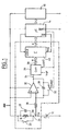
- the polling of this consumption is made by a hardware circuit of which a schematic diagram is given in FIG. 1.
- the consumption of this circuit is very small, of the order of 0.2 ⁇ A, a value that is quite acceptable even for permanent operation.
- This circuit 10 is connected on the one hand to the battery 12 whose current I p will be measured and, on the other hand, to the microcontroller 14, which is of a conventional type, making it possible to execute the implementation software of the device and including read-only memories, timers, DMA controllers, interrupt system, clock, etc.
- This microcontroller 14 is itself interfaced to a circuit 16 containing the dedicated electronics of the device with its stimulation stages, detection amplifiers, sensor processing lines, telemetry system, voltage, current and time references, etc. .
- the battery 12 supplies all the electronic circuits of the device and also provides the energy of the stimulation pulses.
- the current I p supplied by this battery 12 passes through the measurement resistor 18 when the current scanning is activated, that is to say when a switch 20 is open (if there is no longer any need to perform this scan, for example after implantation of the device, the switch 20 will be closed and the circuitry of the cell 10 glandalimentée).
- the capacitor 22, in parallel with the resistor 18, serves to filter the fast consumption transients passing through this resistor.
- the current Ip passing through the resistor 18 produces a voltage V m proportional to the current at 24.
- This voltage is integrated by the circuit consisting of the resistor 26, the capacitor 28 and the operational amplifier 30.
- the integration time constant is chosen relatively short, typically 50 ms to avoid saturation of the amplifier 30.
- the integration cycle is defined by the CLKINT signal produced by the microcontroller 14 which controls a switch 32.
- the switch 32 is open and, at the end of the integration, the integrated voltage present at 34 at the output of the amplifier 30 is converted into a digital value by the analog / digital converter 36.
- the switch 32 is then closed to discharge the capacitor 28 before resuming a new integration cycle of 50 ms.
- Values integration elementals over 50 ms, delivered at 38 at the output of the converter 36, are summed by the adder 40, for a time fixed by the signal RAZ produced by the microcontroller 14.
- This summation duration is chosen sufficiently long, typically of the order of 6 s, to be able to integrate several cardiac cycles of the device.
- the result of the adder in two bytes, is read by the microcontroller in two stages (by the selection signal UB / LB for selecting the first byte and then the second byte) .
- the microcontroller 14 When the microcontroller 14 has thus acquired an average value of the current I p on the battery for 6 s, it resets the adder 40 by the signal RAZ in order to start a new cycle of integration of the current of the battery.
- a measurement of the consumption every 6 seconds gives an appropriate representation of both the overall consumption of the device circuits and the consumption related to the stimulation.
- the resolution of the measurement is chosen sufficiently low to discriminate the start or stop of the main functional blocks of the prosthesis, as well as to discriminate changes in the stimulation parameters. This resolution must be less than 1 ⁇ A, advantageously chosen of the order of 0.16 ⁇ A.
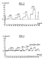
- FIG. 2 shows the variation of the current for various probe impedance values in the absence of detected cardiac signals: when no probe is connected, the current is at a reference value I 0 ; when a probe is connected, two consumption levels can be observed, corresponding respectively to the connection of the ventricular probe, followed by the connection of the atrial probe.
- FIG. 2 shows the current variations in the case of a high impedance connection (3 k ⁇ ) and then disconnection of this probe and connection of a slightly lower impedance probe (2 k ⁇ ), etc.
- the called current is of course the higher the impedance of the probe is low and we see that the variation of the called current is detectable even for high impedance probes (3 k ⁇ ), and even if only the ventricular probe is connected (first stage of variation), which is especially in the case of a simple chamber model.
- FIG. 3 shows the variations of the current called as a function of the frequency of the cardiac signals detected by the device, for various increasing frequencies of the rhythm: 61 cpm, 70 cpm, 80 cpm, ...
- the invention provides for counting the spontaneous ventricular depolarizations (R waves).
- This wave counting system R which in addition provides additional security, will be described later with reference to FIG. R wave counting is however optional, if the current measurement of the battery provides a resolution high enough to suffice on its own.
- Figures 4 and 5 are flowcharts detailing the successive steps of implementation of the invention, to detect the implantation ( Figure 4) and then appropriately configure the stimulation / detection polarity of the device ( Figure 5).
- the implant is configured to deliver stimulation simultaneously in bipolar and monopolar mode: whether or not the housing is in contact with In the patient's tissues, ventricular training will be effective once a ventricular lead has been implanted and connected to the prosthesis.
- an RPP3K indicator is set to 0 to indicate that the apparatus is not implanted, and programmable thresholds are defined: R-wave count (typically 100), and SMC consumption threshold, corresponding to a suspicion of implantation; the threshold of consumption is preferably initialized to the value of the current consumed by the prosthesis at 37 ° C on infinite load, increased by a significant programmable value, indicative of a possible implantation (typically 500 nA). The implant detection cycle is then started ("ON").
- the device executes a delay of duration greater than or equal to the duration of a measurement of the current of the battery, for example a time delay of 6.25 s (step 402).
- step 406 If the verification performed in steps 405 and 406 is positive, it should be checked before deciding whether the prosthesis is actually connected to these probes and therefore implanted. This confirmation must, however, be made after a delay (step 407) allowing the practitioner who connected the probe and placed the housing in the implantation pocket to reinterpret quickly to refine the conditions of implantation (position of the probes, the housing, ligatures , etc.), for example for 5 minutes.
- the next phase consists of searching for the polarity of the probes present, to choose, preferably, a bipolar detection configuration if a bipolar probe is connected, and a monopolar stimulation configuration by default.
- the polarity search begins with the ventricular probe (steps 501 to 504) and then, if the apparatus is a dual chamber (step 505), continues by looking for polarity of the atrial probe (steps 506 to 510).
- Step 501 is an impedance measurement of the ventricular probe in bipolar mode, i.e., between the proximal electrode ("RING") and the distal electrode (“TIP").
- the probe is a monopolar probe (step 504) and the stimulation and detection are programmed in monopolar mode.
- Step 505 tests whether the model of the apparatus is of the double chamber type, because in this case, it is also necessary to configure the ear stage (steps 506 to 509, counterparts of steps 501 to 504).
- step 510 the automatic configuration of the device is completed, and the algorithm is disabled.
- this step 510 would be replaced by the scanning of another stage following the same principle, to check which type of probe it is connected and then configure it automatically.
Landscapes
- Health & Medical Sciences (AREA)
- Heart & Thoracic Surgery (AREA)
- Life Sciences & Earth Sciences (AREA)
- Radiology & Medical Imaging (AREA)
- Cardiology (AREA)
- Engineering & Computer Science (AREA)
- Biomedical Technology (AREA)
- Nuclear Medicine, Radiotherapy & Molecular Imaging (AREA)
- Biophysics (AREA)
- Animal Behavior & Ethology (AREA)
- General Health & Medical Sciences (AREA)
- Public Health (AREA)
- Veterinary Medicine (AREA)
- Electrotherapy Devices (AREA)
- Measurement Of The Respiration, Hearing Ability, Form, And Blood Characteristics Of Living Organisms (AREA)
- Measuring And Recording Apparatus For Diagnosis (AREA)
Applications Claiming Priority (1)
| Application Number | Priority Date | Filing Date | Title |
|---|---|---|---|
| FR0408162A FR2873298B1 (fr) | 2004-07-23 | 2004-07-23 | Stimulateur cardiaque implantable a detection automatique de la mise en place d'une sonde et de l'implantation du boitier |
Publications (2)
| Publication Number | Publication Date |
|---|---|
| EP1618923A1 true EP1618923A1 (de) | 2006-01-25 |
| EP1618923B1 EP1618923B1 (de) | 2007-02-14 |
Family
ID=34947969
Family Applications (1)
| Application Number | Title | Priority Date | Filing Date |
|---|---|---|---|
| EP05291566A Expired - Lifetime EP1618923B1 (de) | 2004-07-23 | 2005-07-21 | Implantable cardiac stimulation device with automatic detection of the installation of a probe and of the implantation of the housing |
Country Status (5)
| Country | Link |
|---|---|
| US (1) | US7440801B2 (de) |
| EP (1) | EP1618923B1 (de) |
| AT (1) | ATE353690T1 (de) |
| DE (1) | DE602005000554T2 (de) |
| FR (1) | FR2873298B1 (de) |
Cited By (3)
| Publication number | Priority date | Publication date | Assignee | Title |
|---|---|---|---|---|
| WO2008088569A1 (en) * | 2007-01-18 | 2008-07-24 | Medtronic, Inc. | Bi-directional connector assembly for an implantable medical device |
| EP3023122A1 (de) | 2014-11-19 | 2016-05-25 | Sorin CRM SAS | Aktive implantierbare medizinische vorrichtung zur kombinierten ausführung von herz- und peripheren behandlungen, die mit mitteln zur detektion und automatischen kopplung an den sonden ausgestattet ist |
| EP3042692A1 (de) | 2014-11-19 | 2016-07-13 | Sorin CRM SAS | Implantierbare medizinische vorrichtung zur behandlung des herzens und der peripherie mit mitteln zur zulassung oder unterdrückung der behandlung auf basis von erfassten signalen |
Families Citing this family (6)
| Publication number | Priority date | Publication date | Assignee | Title |
|---|---|---|---|---|
| WO2006124787A2 (en) * | 2005-05-13 | 2006-11-23 | Cardiocore Lab, Inc. | Method and apparatus for sequenced extraction from electrocardiogramic waveforms |
| US8241197B2 (en) * | 2005-12-31 | 2012-08-14 | John W Royalty | Method of generating a cardiogram with a magnet |
| US8688217B2 (en) * | 2008-10-24 | 2014-04-01 | Boston Scientific Neuromodulation Corporation | Method to detect proper lead connection in an implantable stimulation system |
| US8260424B2 (en) * | 2008-10-24 | 2012-09-04 | Boston Scientific Neuromodulation Corporation | Systems and methods for detecting a loss of electrical connectivity between components of implantable medical lead systems |
| EP4335490B1 (de) * | 2017-11-13 | 2025-09-10 | The Charles Stark Draper Laboratory, Inc. | Implantierbare intra- und transkörper-drahtlosnetzwerke für therapien |
| US11998749B2 (en) | 2019-10-21 | 2024-06-04 | Biotronik Se & Co. Kg | Implantable medical device |
Citations (5)
| Publication number | Priority date | Publication date | Assignee | Title |
|---|---|---|---|---|
| US5370666A (en) | 1992-06-05 | 1994-12-06 | Siemens-Elema Ab | Pacemaker with power-consuming component inhibited during storage |
| US5522856A (en) | 1994-09-20 | 1996-06-04 | Vitatron Medical, B.V. | Pacemaker with improved shelf storage capacity |
| US5534018A (en) * | 1994-11-30 | 1996-07-09 | Medtronic, Inc. | Automatic lead recognition for implantable medical device |
| US6016447A (en) * | 1998-10-27 | 2000-01-18 | Medtronic, Inc. | Pacemaker implant recognition |
| EP1438985A1 (de) * | 2003-01-17 | 2004-07-21 | Ela Medical | Implantierbare medizinische Vorrichtung wie ein Herzschrittmacher mit einer Einrichtung zur Feststellung der Präsenz und des Types einer angeordneten Sonde |
Family Cites Families (3)
| Publication number | Priority date | Publication date | Assignee | Title |
|---|---|---|---|---|
| US537066A (en) | 1895-04-09 | Shelf-roller | ||
| US5713932A (en) * | 1996-10-28 | 1998-02-03 | Medtronic, Inc. | Method and apparatus for determining atrial lead disclocation and confirming diagnosis of atrial tachyarrhythimias |
| US6317633B1 (en) * | 1999-01-19 | 2001-11-13 | Medtronic, Inc. | Implantable lead functional status monitor and method |
-
2004
- 2004-07-23 FR FR0408162A patent/FR2873298B1/fr not_active Expired - Fee Related
-
2005
- 2005-07-20 US US11/186,623 patent/US7440801B2/en active Active
- 2005-07-21 DE DE602005000554T patent/DE602005000554T2/de not_active Expired - Lifetime
- 2005-07-21 AT AT05291566T patent/ATE353690T1/de not_active IP Right Cessation
- 2005-07-21 EP EP05291566A patent/EP1618923B1/de not_active Expired - Lifetime
Patent Citations (5)
| Publication number | Priority date | Publication date | Assignee | Title |
|---|---|---|---|---|
| US5370666A (en) | 1992-06-05 | 1994-12-06 | Siemens-Elema Ab | Pacemaker with power-consuming component inhibited during storage |
| US5522856A (en) | 1994-09-20 | 1996-06-04 | Vitatron Medical, B.V. | Pacemaker with improved shelf storage capacity |
| US5534018A (en) * | 1994-11-30 | 1996-07-09 | Medtronic, Inc. | Automatic lead recognition for implantable medical device |
| US6016447A (en) * | 1998-10-27 | 2000-01-18 | Medtronic, Inc. | Pacemaker implant recognition |
| EP1438985A1 (de) * | 2003-01-17 | 2004-07-21 | Ela Medical | Implantierbare medizinische Vorrichtung wie ein Herzschrittmacher mit einer Einrichtung zur Feststellung der Präsenz und des Types einer angeordneten Sonde |
Cited By (7)
| Publication number | Priority date | Publication date | Assignee | Title |
|---|---|---|---|---|
| WO2008088569A1 (en) * | 2007-01-18 | 2008-07-24 | Medtronic, Inc. | Bi-directional connector assembly for an implantable medical device |
| US7933652B2 (en) | 2007-01-18 | 2011-04-26 | Medtronic, Inc. | Bi-directional connector assembly for an implantable medical device |
| US8364268B2 (en) | 2007-01-18 | 2013-01-29 | Medtronic, Inc. | Bi-directional connector assembly for an implantable medical device |
| EP3023122A1 (de) | 2014-11-19 | 2016-05-25 | Sorin CRM SAS | Aktive implantierbare medizinische vorrichtung zur kombinierten ausführung von herz- und peripheren behandlungen, die mit mitteln zur detektion und automatischen kopplung an den sonden ausgestattet ist |
| EP3042692A1 (de) | 2014-11-19 | 2016-07-13 | Sorin CRM SAS | Implantierbare medizinische vorrichtung zur behandlung des herzens und der peripherie mit mitteln zur zulassung oder unterdrückung der behandlung auf basis von erfassten signalen |
| US9795798B2 (en) | 2014-11-19 | 2017-10-24 | Sorin Crm Sas | Active implantable medical device with cardiac lead and peripheral lead discrimination |
| US9808638B2 (en) | 2014-11-19 | 2017-11-07 | Sorin Crm Sas | Active implantable medical device with cardiac lead and peripheral lead discrimination |
Also Published As
| Publication number | Publication date |
|---|---|
| DE602005000554T2 (de) | 2007-11-22 |
| US7440801B2 (en) | 2008-10-21 |
| US20060052833A1 (en) | 2006-03-09 |
| DE602005000554D1 (de) | 2007-03-29 |
| ATE353690T1 (de) | 2007-03-15 |
| FR2873298B1 (fr) | 2006-09-22 |
| EP1618923B1 (de) | 2007-02-14 |
| FR2873298A1 (fr) | 2006-01-27 |
Similar Documents
| Publication | Publication Date | Title |
|---|---|---|
| EP1438985B1 (de) | Implantierbare medizinische Vorrichtung wie ein Herzschrittmacher mit einer Einrichtung zur Feststellung der Präsenz und des Types einer angeordneten Sonde | |
| EP0605264B1 (de) | Implantierbarer Herzschittmacher | |
| FR2602146A1 (fr) | Circuit generateur d'impulsions de stimulation pour stimulateur cardiaque | |
| EP0862927B1 (de) | Multi-Ort Herzschrittmacher zur Behandlung von Herzinsuffizienzen mit Reizimpulsen | |
| FR2494119A1 (fr) | Stimulateur cardiaque programmable multimode commande par un microprocesseur | |
| EP2926863B1 (de) | Verwendung eines implantierbaren Herzschrittmachers zur Stimulation, Defibrillation und/oder Resynchronisation des Herzmuskels als Impulsgenerator zur Vagus-Nerv-Stimulation (VNS) | |
| FR2712500A1 (fr) | Procédé de commande automatique du seuil de détection du rythme cardiaque dans un appareil implantable. | |
| EP0770412A1 (de) | Medische Vorrichtung sowie aktiver implantierbarer Defibrillator/Kardiovertierer zum Vorhofsdefibrillieren | |
| FR2901146A1 (fr) | Dispositif medical implantable actif de stimulation cardiaque, resynchronisation, cardioversion et/ou defibrillation, comportant des moyens de detection d'artefacts de bruit ventriculaire | |
| FR2680093A1 (fr) | Procede de controle de l'energie de stimulation dans un stimulateur cardiaque. | |
| EP1618923B1 (de) | Implantable cardiac stimulation device with automatic detection of the installation of a probe and of the implantation of the housing | |
| EP3345651B1 (de) | System zur erfassungsüberprüfung in implantierbaren drahtlosen herzschrittmachern | |
| EP1405654B1 (de) | Aktives implantierbares medizinisches Gerät, wie Herzschrittmacher, Defibrillatoren, Kardiovertierer und/oder Multisitevorrichtungen, mit Mitteln zur Feststellung der durchschnittlichen hemodynamischen Kennzahl | |
| EP2374503B1 (de) | Aktive implantierbare medizinische Vorrichtung für Vagusnervstimulation mit Optimisierung der Ventrikelfüllung | |
| FR2808212A1 (fr) | Procede et systeme de determination d'un seuil de bruit dans un systeme de cardiostimulation | |
| EP2803385B1 (de) | Implantierbares CRT-Gerät zur Stimulation beider Ventrikel und zur Erkennung von Erfassungsverlusten und anodischen Stimulationen | |
| EP1433497B1 (de) | Aktive implantierbare medizinische Vorrichtung mit Detektierung von evozierten Herzpotentialen, insbesondere Atrialpotentialen | |
| EP3025758B1 (de) | Aktive implantierbare medizinische vorrichtung, insbesondere vom typ leadless-kapsel, mit detektion der zyklusweisen erfassung durch analyse eines signals für die endokardiale beschleunigung | |
| EP1543864B1 (de) | Implantierbares aktives medizinisches Gerät mit Ventrikel-Resynchronisationsmodus | |
| FR2829030A1 (fr) | Dispositif medical actif implantable, notamment stimulateur cardiaque, defibrillateur, cardiovecteur ou dispositif multisite, comprenant des moyens d'ajustement cycle a cycle de l'amplitude de stimulation | |
| EP1080744A1 (de) | Implantierbarer Kardiostimulator mit automatischer Anpassung des Stimulationspulsniveaus | |
| EP2881140B1 (de) | Implantierbare aktive medizinische Vorrichtung zur Doppelkammer-Stimulation für die Behandlung von Herzinsuffizienz mit erhaltener Auswurffraktion (HFpEF) | |
| EP3042693B1 (de) | Aktive implantierbare medizinische vorrichtung, insbesondere vom typ autonome kapsel, mit dynamischer optimierung der energie der stimulationsimpulse | |
| EP1800710B1 (de) | Aktive implantierbare medizinische Vorrichtung, insbesondere Herzschrittmacher, Defibrillator, und/oder Kardiovertierer des AAI/DDD-Typs, mit Mitteln zur automatischen Moduseinstellung nach automatischer Implantierungsdetektion | |
| FR2793146A1 (fr) | Dispositif medical implantable actif, notamment stimulateur cardiaque, defibrillateur et/ou cardioverteur de type ddd/aai a fonctionnement optimise a l'effort |
Legal Events
| Date | Code | Title | Description |
|---|---|---|---|
| PUAI | Public reference made under article 153(3) epc to a published international application that has entered the european phase |
Free format text: ORIGINAL CODE: 0009012 |
|
| AK | Designated contracting states |
Kind code of ref document: A1 Designated state(s): AT BE BG CH CY CZ DE DK EE ES FI FR GB GR HU IE IS IT LI LT LU LV MC NL PL PT RO SE SI SK TR |
|
| AX | Request for extension of the european patent |
Extension state: AL BA HR MK YU |
|
| 17P | Request for examination filed |
Effective date: 20060619 |
|
| AKX | Designation fees paid |
Designated state(s): AT BE BG CH CY CZ DE DK EE ES FI FR GB GR HU IE IS IT LI LT LU LV MC NL PL PT RO SE SI SK TR |
|
| GRAP | Despatch of communication of intention to grant a patent |
Free format text: ORIGINAL CODE: EPIDOSNIGR1 |
|
| GRAS | Grant fee paid |
Free format text: ORIGINAL CODE: EPIDOSNIGR3 |
|
| GRAA | (expected) grant |
Free format text: ORIGINAL CODE: 0009210 |
|
| AK | Designated contracting states |
Kind code of ref document: B1 Designated state(s): AT BE BG CH CY CZ DE DK EE ES FI FR GB GR HU IE IS IT LI LT LU LV MC NL PL PT RO SE SI SK TR |
|
| PG25 | Lapsed in a contracting state [announced via postgrant information from national office to epo] |
Ref country code: DK Free format text: LAPSE BECAUSE OF FAILURE TO SUBMIT A TRANSLATION OF THE DESCRIPTION OR TO PAY THE FEE WITHIN THE PRESCRIBED TIME-LIMIT Effective date: 20070214 Ref country code: SI Free format text: LAPSE BECAUSE OF FAILURE TO SUBMIT A TRANSLATION OF THE DESCRIPTION OR TO PAY THE FEE WITHIN THE PRESCRIBED TIME-LIMIT Effective date: 20070214 Ref country code: AT Free format text: LAPSE BECAUSE OF FAILURE TO SUBMIT A TRANSLATION OF THE DESCRIPTION OR TO PAY THE FEE WITHIN THE PRESCRIBED TIME-LIMIT Effective date: 20070214 Ref country code: PL Free format text: LAPSE BECAUSE OF FAILURE TO SUBMIT A TRANSLATION OF THE DESCRIPTION OR TO PAY THE FEE WITHIN THE PRESCRIBED TIME-LIMIT Effective date: 20070214 Ref country code: FI Free format text: LAPSE BECAUSE OF FAILURE TO SUBMIT A TRANSLATION OF THE DESCRIPTION OR TO PAY THE FEE WITHIN THE PRESCRIBED TIME-LIMIT Effective date: 20070214 Ref country code: NL Free format text: LAPSE BECAUSE OF FAILURE TO SUBMIT A TRANSLATION OF THE DESCRIPTION OR TO PAY THE FEE WITHIN THE PRESCRIBED TIME-LIMIT Effective date: 20070214 |
|
| REG | Reference to a national code |
Ref country code: GB Ref legal event code: FG4D Free format text: NOT ENGLISH |
|
| REG | Reference to a national code |
Ref country code: CH Ref legal event code: EP |
|
| REF | Corresponds to: |
Ref document number: 602005000554 Country of ref document: DE Date of ref document: 20070329 Kind code of ref document: P |
|
| REG | Reference to a national code |
Ref country code: IE Ref legal event code: FG4D Free format text: LANGUAGE OF EP DOCUMENT: FRENCH |
|
| PG25 | Lapsed in a contracting state [announced via postgrant information from national office to epo] |
Ref country code: BG Free format text: LAPSE BECAUSE OF FAILURE TO SUBMIT A TRANSLATION OF THE DESCRIPTION OR TO PAY THE FEE WITHIN THE PRESCRIBED TIME-LIMIT Effective date: 20070514 |
|
| GBT | Gb: translation of ep patent filed (gb section 77(6)(a)/1977) |
Effective date: 20070424 |
|
| PG25 | Lapsed in a contracting state [announced via postgrant information from national office to epo] |
Ref country code: ES Free format text: LAPSE BECAUSE OF FAILURE TO SUBMIT A TRANSLATION OF THE DESCRIPTION OR TO PAY THE FEE WITHIN THE PRESCRIBED TIME-LIMIT Effective date: 20070525 |
|
| REG | Reference to a national code |
Ref country code: SE Ref legal event code: TRGR |
|
| PG25 | Lapsed in a contracting state [announced via postgrant information from national office to epo] |
Ref country code: IS Free format text: LAPSE BECAUSE OF FAILURE TO SUBMIT A TRANSLATION OF THE DESCRIPTION OR TO PAY THE FEE WITHIN THE PRESCRIBED TIME-LIMIT Effective date: 20070614 |
|
| PG25 | Lapsed in a contracting state [announced via postgrant information from national office to epo] |
Ref country code: PT Free format text: LAPSE BECAUSE OF FAILURE TO SUBMIT A TRANSLATION OF THE DESCRIPTION OR TO PAY THE FEE WITHIN THE PRESCRIBED TIME-LIMIT Effective date: 20070716 |
|
| NLV1 | Nl: lapsed or annulled due to failure to fulfill the requirements of art. 29p and 29m of the patents act | ||
| PG25 | Lapsed in a contracting state [announced via postgrant information from national office to epo] |
Ref country code: SK Free format text: LAPSE BECAUSE OF FAILURE TO SUBMIT A TRANSLATION OF THE DESCRIPTION OR TO PAY THE FEE WITHIN THE PRESCRIBED TIME-LIMIT Effective date: 20070214 |
|
| PLBE | No opposition filed within time limit |
Free format text: ORIGINAL CODE: 0009261 |
|
| STAA | Information on the status of an ep patent application or granted ep patent |
Free format text: STATUS: NO OPPOSITION FILED WITHIN TIME LIMIT |
|
| PG25 | Lapsed in a contracting state [announced via postgrant information from national office to epo] |
Ref country code: CZ Free format text: LAPSE BECAUSE OF FAILURE TO SUBMIT A TRANSLATION OF THE DESCRIPTION OR TO PAY THE FEE WITHIN THE PRESCRIBED TIME-LIMIT Effective date: 20070214 Ref country code: RO Free format text: LAPSE BECAUSE OF FAILURE TO SUBMIT A TRANSLATION OF THE DESCRIPTION OR TO PAY THE FEE WITHIN THE PRESCRIBED TIME-LIMIT Effective date: 20070214 |
|
| 26N | No opposition filed |
Effective date: 20071115 |
|
| BERE | Be: lapsed |
Owner name: ELA MEDICAL Effective date: 20070731 |
|
| PG25 | Lapsed in a contracting state [announced via postgrant information from national office to epo] |
Ref country code: LV Free format text: LAPSE BECAUSE OF FAILURE TO SUBMIT A TRANSLATION OF THE DESCRIPTION OR TO PAY THE FEE WITHIN THE PRESCRIBED TIME-LIMIT Effective date: 20070214 |
|
| PG25 | Lapsed in a contracting state [announced via postgrant information from national office to epo] |
Ref country code: LT Free format text: LAPSE BECAUSE OF FAILURE TO SUBMIT A TRANSLATION OF THE DESCRIPTION OR TO PAY THE FEE WITHIN THE PRESCRIBED TIME-LIMIT Effective date: 20070214 |
|
| PG25 | Lapsed in a contracting state [announced via postgrant information from national office to epo] |
Ref country code: MC Free format text: LAPSE BECAUSE OF NON-PAYMENT OF DUE FEES Effective date: 20070731 Ref country code: GR Free format text: LAPSE BECAUSE OF FAILURE TO SUBMIT A TRANSLATION OF THE DESCRIPTION OR TO PAY THE FEE WITHIN THE PRESCRIBED TIME-LIMIT Effective date: 20070515 |
|
| PG25 | Lapsed in a contracting state [announced via postgrant information from national office to epo] |
Ref country code: BE Free format text: LAPSE BECAUSE OF NON-PAYMENT OF DUE FEES Effective date: 20070731 |
|
| PG25 | Lapsed in a contracting state [announced via postgrant information from national office to epo] |
Ref country code: EE Free format text: LAPSE BECAUSE OF FAILURE TO SUBMIT A TRANSLATION OF THE DESCRIPTION OR TO PAY THE FEE WITHIN THE PRESCRIBED TIME-LIMIT Effective date: 20070214 |
|
| PG25 | Lapsed in a contracting state [announced via postgrant information from national office to epo] |
Ref country code: CY Free format text: LAPSE BECAUSE OF FAILURE TO SUBMIT A TRANSLATION OF THE DESCRIPTION OR TO PAY THE FEE WITHIN THE PRESCRIBED TIME-LIMIT Effective date: 20070214 |
|
| PG25 | Lapsed in a contracting state [announced via postgrant information from national office to epo] |
Ref country code: LU Free format text: LAPSE BECAUSE OF NON-PAYMENT OF DUE FEES Effective date: 20070721 |
|
| PG25 | Lapsed in a contracting state [announced via postgrant information from national office to epo] |
Ref country code: HU Free format text: LAPSE BECAUSE OF FAILURE TO SUBMIT A TRANSLATION OF THE DESCRIPTION OR TO PAY THE FEE WITHIN THE PRESCRIBED TIME-LIMIT Effective date: 20070815 Ref country code: TR Free format text: LAPSE BECAUSE OF FAILURE TO SUBMIT A TRANSLATION OF THE DESCRIPTION OR TO PAY THE FEE WITHIN THE PRESCRIBED TIME-LIMIT Effective date: 20070214 |
|
| REG | Reference to a national code |
Ref country code: CH Ref legal event code: PL |
|
| PG25 | Lapsed in a contracting state [announced via postgrant information from national office to epo] |
Ref country code: LI Free format text: LAPSE BECAUSE OF NON-PAYMENT OF DUE FEES Effective date: 20090731 Ref country code: CH Free format text: LAPSE BECAUSE OF NON-PAYMENT OF DUE FEES Effective date: 20090731 |
|
| PGFP | Annual fee paid to national office [announced via postgrant information from national office to epo] |
Ref country code: IE Payment date: 20120710 Year of fee payment: 8 Ref country code: SE Payment date: 20120711 Year of fee payment: 8 |
|
| REG | Reference to a national code |
Ref country code: SE Ref legal event code: EUG |
|
| REG | Reference to a national code |
Ref country code: IE Ref legal event code: MM4A |
|
| PG25 | Lapsed in a contracting state [announced via postgrant information from national office to epo] |
Ref country code: SE Free format text: LAPSE BECAUSE OF NON-PAYMENT OF DUE FEES Effective date: 20130722 |
|
| PG25 | Lapsed in a contracting state [announced via postgrant information from national office to epo] |
Ref country code: IE Free format text: LAPSE BECAUSE OF NON-PAYMENT OF DUE FEES Effective date: 20130721 |
|
| REG | Reference to a national code |
Ref country code: FR Ref legal event code: PLFP Year of fee payment: 12 |
|
| REG | Reference to a national code |
Ref country code: FR Ref legal event code: PLFP Year of fee payment: 13 |
|
| REG | Reference to a national code |
Ref country code: FR Ref legal event code: PLFP Year of fee payment: 14 |
|
| P01 | Opt-out of the competence of the unified patent court (upc) registered |
Effective date: 20230714 |
|
| PGFP | Annual fee paid to national office [announced via postgrant information from national office to epo] |
Ref country code: IT Payment date: 20230707 Year of fee payment: 19 Ref country code: GB Payment date: 20230725 Year of fee payment: 19 |
|
| PGFP | Annual fee paid to national office [announced via postgrant information from national office to epo] |
Ref country code: FR Payment date: 20230727 Year of fee payment: 19 Ref country code: DE Payment date: 20230712 Year of fee payment: 19 |
|
| REG | Reference to a national code |
Ref country code: DE Ref legal event code: R119 Ref document number: 602005000554 Country of ref document: DE |
|
| GBPC | Gb: european patent ceased through non-payment of renewal fee |
Effective date: 20240721 |
|
| PG25 | Lapsed in a contracting state [announced via postgrant information from national office to epo] |
Ref country code: DE Free format text: LAPSE BECAUSE OF NON-PAYMENT OF DUE FEES Effective date: 20250201 |
|
| PG25 | Lapsed in a contracting state [announced via postgrant information from national office to epo] |
Ref country code: FR Free format text: LAPSE BECAUSE OF NON-PAYMENT OF DUE FEES Effective date: 20240731 |
|
| PG25 | Lapsed in a contracting state [announced via postgrant information from national office to epo] |
Ref country code: GB Free format text: LAPSE BECAUSE OF NON-PAYMENT OF DUE FEES Effective date: 20240721 |
|
| PG25 | Lapsed in a contracting state [announced via postgrant information from national office to epo] |
Ref country code: IT Free format text: LAPSE BECAUSE OF NON-PAYMENT OF DUE FEES Effective date: 20240721 |