EP1619335A2 - Justierbares Band für Fenster, Türen und dergleichen - Google Patents
Justierbares Band für Fenster, Türen und dergleichen Download PDFInfo
- Publication number
- EP1619335A2 EP1619335A2 EP05014167A EP05014167A EP1619335A2 EP 1619335 A2 EP1619335 A2 EP 1619335A2 EP 05014167 A EP05014167 A EP 05014167A EP 05014167 A EP05014167 A EP 05014167A EP 1619335 A2 EP1619335 A2 EP 1619335A2
- Authority
- EP
- European Patent Office
- Prior art keywords
- wing
- band
- frame
- guide
- hinge part
- Prior art date
- Legal status (The legal status is an assumption and is not a legal conclusion. Google has not performed a legal analysis and makes no representation as to the accuracy of the status listed.)
- Granted
Links
Images

Classifications
-
- E—FIXED CONSTRUCTIONS
- E05—LOCKS; KEYS; WINDOW OR DOOR FITTINGS; SAFES
- E05D—HINGES OR SUSPENSION DEVICES FOR DOORS, WINDOWS OR WINGS
- E05D7/00—Hinges or pivots of special construction
- E05D7/04—Hinges adjustable relative to the wing or the frame
- E05D7/0415—Hinges adjustable relative to the wing or the frame with adjusting drive means
-
- E—FIXED CONSTRUCTIONS
- E05—LOCKS; KEYS; WINDOW OR DOOR FITTINGS; SAFES
- E05D—HINGES OR SUSPENSION DEVICES FOR DOORS, WINDOWS OR WINGS
- E05D3/00—Hinges with pins
- E05D3/02—Hinges with pins with one pin
- E05D2003/025—Hinges with pins with one pin having three knuckles
-
- E—FIXED CONSTRUCTIONS
- E05—LOCKS; KEYS; WINDOW OR DOOR FITTINGS; SAFES
- E05D—HINGES OR SUSPENSION DEVICES FOR DOORS, WINDOWS OR WINGS
- E05D5/00—Construction of single parts, e.g. the parts for attachment
- E05D5/02—Parts for attachment, e.g. flaps
- E05D5/0215—Parts for attachment, e.g. flaps for attachment to profile members or the like
- E05D5/0223—Parts for attachment, e.g. flaps for attachment to profile members or the like with parts, e.g. screws, extending through the profile wall or engaging profile grooves
- E05D5/0238—Parts for attachment, e.g. flaps for attachment to profile members or the like with parts, e.g. screws, extending through the profile wall or engaging profile grooves with parts engaging profile grooves
-
- E—FIXED CONSTRUCTIONS
- E05—LOCKS; KEYS; WINDOW OR DOOR FITTINGS; SAFES
- E05D—HINGES OR SUSPENSION DEVICES FOR DOORS, WINDOWS OR WINGS
- E05D7/00—Hinges or pivots of special construction
- E05D7/04—Hinges adjustable relative to the wing or the frame
- E05D7/0415—Hinges adjustable relative to the wing or the frame with adjusting drive means
- E05D7/0423—Screw-and-nut mechanisms
-
- E—FIXED CONSTRUCTIONS
- E05—LOCKS; KEYS; WINDOW OR DOOR FITTINGS; SAFES
- E05Y—INDEXING SCHEME ASSOCIATED WITH SUBCLASSES E05D AND E05F, RELATING TO CONSTRUCTION ELEMENTS, ELECTRIC CONTROL, POWER SUPPLY, POWER SIGNAL OR TRANSMISSION, USER INTERFACES, MOUNTING OR COUPLING, DETAILS, ACCESSORIES, AUXILIARY OPERATIONS NOT OTHERWISE PROVIDED FOR, APPLICATION THEREOF
- E05Y2201/00—Constructional elements; Accessories therefor
- E05Y2201/60—Suspension or transmission members; Accessories therefor
- E05Y2201/622—Suspension or transmission members elements
- E05Y2201/638—Cams; Ramps
-
- E—FIXED CONSTRUCTIONS
- E05—LOCKS; KEYS; WINDOW OR DOOR FITTINGS; SAFES
- E05Y—INDEXING SCHEME ASSOCIATED WITH SUBCLASSES E05D AND E05F, RELATING TO CONSTRUCTION ELEMENTS, ELECTRIC CONTROL, POWER SUPPLY, POWER SIGNAL OR TRANSMISSION, USER INTERFACES, MOUNTING OR COUPLING, DETAILS, ACCESSORIES, AUXILIARY OPERATIONS NOT OTHERWISE PROVIDED FOR, APPLICATION THEREOF
- E05Y2900/00—Application of doors, windows, wings or fittings thereof
- E05Y2900/10—Application of doors, windows, wings or fittings thereof for buildings or parts thereof
- E05Y2900/13—Type of wing
- E05Y2900/132—Doors
-
- E—FIXED CONSTRUCTIONS
- E05—LOCKS; KEYS; WINDOW OR DOOR FITTINGS; SAFES
- E05Y—INDEXING SCHEME ASSOCIATED WITH SUBCLASSES E05D AND E05F, RELATING TO CONSTRUCTION ELEMENTS, ELECTRIC CONTROL, POWER SUPPLY, POWER SIGNAL OR TRANSMISSION, USER INTERFACES, MOUNTING OR COUPLING, DETAILS, ACCESSORIES, AUXILIARY OPERATIONS NOT OTHERWISE PROVIDED FOR, APPLICATION THEREOF
- E05Y2900/00—Application of doors, windows, wings or fittings thereof
- E05Y2900/10—Application of doors, windows, wings or fittings thereof for buildings or parts thereof
- E05Y2900/13—Type of wing
- E05Y2900/148—Windows
Definitions
- the invention relates to an adjustable band, in particular for mounting on hollow profiles, the preamble of claim 1 corresponding type.
- the present invention has for its object to provide an adjustable band, wherein the guide function is improved during the adjustment process.
- the hinge part comprises a guide leg, which is received in a guide chamber, which is provided in the fastening part, displaceable in the adjustment direction leader, a guide in the adjustment direction relative to each other displaceable components takes place over a large area.
- the guiding function is improved, on the other hand, the forces introduced by the holding forces into the material per unit area are reduced by the large area, whereby the band of the invention is also suitable for heavy wings, such as fire doors and the like.
- a groove extending transversely to the adjustment direction is provided in the guide leg.
- the band according to the invention comprises a displaceable in the fastening part transversely to the adjustment adjustment, which is in engagement with the groove.
- a displacement of the adjustment leads through the inclined to its direction of adjustment groove to the fact that the guide leg and with it the hinge part is forcibly displaced in the adjustment direction.
- the adjusting element is rod-shaped and has a lateral extension which engages in the groove in the guide leg.
- the fastening part comprises in a particularly preferred embodiment, a parallel to the hinge axis extending receptacle along which the adjusting element can be displaced.
- a particularly effective clamping can be achieved when fixing screws act on the parallel to the adjustment direction extending narrow sides of the guide leg.
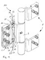
- the designated in the drawing as a whole with 100 band comprises a wing hinge part 1 and a frame hinge part 2.
- the hinge parts 1 and 2 are connected in a known and not explained in more detail here manner about the hinge axis S pivotally.
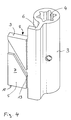
- the wing hinge part 1 comprises a hinge part 3, which has a recess 4 for receiving a hinge pin, not shown in the drawing, defining the hinge axis S (see also FIG. 4).
- the hinge part 3 comprises a guide leg 5, which is connected via an angled portion 6 integral with the recess 4 containing part of the hinge part 3.
- the guide leg 5 has a substantially plate-like shape. With its flat sides 7, 8 and its narrow sides 9, 10 running parallel to the adjustment direction P, it is mounted in a guiding manner in a guide chamber 11, which is provided in a fastening part 12 of the wing hinge part.
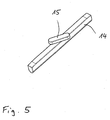
- the guide leg 5 has on its in Figs. 1 and 4 facing the viewer flat side 5, a groove 13. In this groove 13 engages a projection 15 provided on a substantially rod-shaped adjusting element 14 (see FIG. 5).
- the adjusting element 14 is in a receptacle 16 provided for this, which is parallel to the Hinge axis S extends, slidably mounted in the fastening part 12 in the longitudinal direction of the receptacle 26.
- the displacement and fixation of the adjusting element 14 are provided at both end portions of the receptacle 16 provided internal thread 17, 18 are screwed into the grub screws which act on the two ends of the adjusting element 14.
- the fastening part 12 furthermore has a fastening structure 23 which, in its configuration, is adapted to the wing on which the attachment of the band is to take place.
- the fastening structure 23 is not intended to be discussed in the context of this description, since it is irrelevant to the mode of operation of the band for the purpose of adjustability.
Landscapes
- Engineering & Computer Science (AREA)
- Mechanical Engineering (AREA)
- Hinges (AREA)
- Liquid Crystal (AREA)
- Wing Frames And Configurations (AREA)
Abstract
Description
- Die Erfindung betrifft ein justierbares Band, insbesondere zur Montage an Hohlprofilen, der dem Oberbegriff des Anspruchs 1 entsprechenden Art.
- Hohlprofile kommen im modernen Tür- und Fensterbau vielfach zum Einsatz. Sie sind meist aus Aluminiumlegierungen hergestellt.
- Um einen Flügel in dem dazugehörigen Rahmen justieren zu können, ist es beispielsweise aus der DE 40 07 364 C2 bekannt, einen Bandteil in ein Scharnierteil und ein Befestigungsteil zweizuteilen und die Teile in einer zur Scharnierachse des Bandes senkrechten Richtung verlagerbar aneinander anzubringen, wobei eine Führung gegen Bewegungen der beiden Teile relativ zueinander außerhalb der Justierrichtung durch Eingriff von im Querschnitt viereckigen Bolzen in Langlöcher bewirkt wird.
- Ausgehend von der DE 40 07 364 C2 liegt der vorliegenden Erfindung die Aufgabe zugrunde, ein justierbares Band zu schaffen, bei welchem die Führungsfunktion während des Justiervorganges verbessert ist.
- Diese Aufgabe wird durch das in Anspruch 1 wiedergegebene Band gelöst.
- Dadurch, daß das Scharnierteil einen Führungsschenkel umfaßt, der in einer Führungskammer, die in dem Befestigungsteil vorgesehen ist, in Justierrichtung verlagerbar führend aufgenommen ist, findet eine Führung in Verstellrichtung relativ zueinander verlagerbarer Bauteile großflächig statt. Hierdurch wird einerseits die Führungsfunktion verbessert, andererseits sind durch die Großflächigkeit die durch die Haltekräfte in das Material pro Flächeneinheit eingeleiteten Kräfte reduziert, wodurch das erfindungsgemäße Band auch für schwere Flügel, wie Feuerschutztüren und dergleichen, geeignet ist.
- Um die Verstellung in Justierrichtung zwischen dem Scharnierteil und dem Befestigungsteil vornehmen zu können, ist in dem Führungsschenkel eine quer zur Justierrichtung verlaufende Nut vorgesehen.
- Ferner umfaßt das erfindungsgemäße Band ein in dem Befestigungsteil quer zur Verstellrichtung verlagerbares Verstellelement, welches mit der Nut in Eingriff steht. Eine Verlagerung des Verstellelements führt durch die zu dessen Verstellrichtung schräg verlaufende Nut dazu, daß der Führungsschenkel und mit ihm das Scharnierteil in Justierrichtung zwangsverlagert wird.
- Bei einer bevorzugten Ausführungsform des erfindungsgemäßen Bandes ist das Verstellelement stabförmig ausgebildet und weist einen seitlichen Fortsatz auf, der in die Nut in dem Führungsschenkel eingreift.
- Das Befestigungsteil umfaßt bei einer besonders bevorzugten Ausführungsform eine sich parallel zur Scharnierachse erstreckende Aufnahme, entlang welcher das Verstellelement verlagert werden kann.
- Besonders bevorzugt ist es, wenn zur Bewirkung der Verlagerung des Verstellelements an den Enden der Aufnahme Innengewinde vorgesehen sind, in die auf das Verstellelement wirkende Madenschrauben eingedreht sind. Durch diese Maßnahme kann auf einfache Weise das Verstellelement und damit das Scharnierteil in die gewünschte Position gebracht und durch Einklemmen zwischen den beiden Madenschrauben in dieser fixiert werden.
- Ist die gewünschte Justierung des Flügels in dem Rahmen erfolgt, kann eine zusätzliche Sicherung dieser Justierstellung erfolgen, wenn - wie besonders bevorzugt - in die Führungskammer mündende Gewindebohrungen vorgesehen sind, in die Fixierschrauben eindrehbar sind, die mit dem Befestigungsschenkel klemmend in Anlage bringbar sind.
- Eine besonders wirksame Klemmung kann erzielt werden, wenn Fixierschrauben auf die parallel zur Justierrichtung verlaufenden Schmalseiten des Führungsschenkels wirken.
- In der Zeichnung ist ein Ausführungsbeispiel eines erfindungsgemäßen Bandes dargestellt.
- Es zeigen:
- Fig. 1 ein erfindungsgemäßes Band in einer perspektivischen Ansicht von schräg vorn, wobei das Befestigungsteil des Flügelbandteils teilgeschnitten dargestellt ist;
- Fig. 2 das Befestigungsteil in einer perspektivischen Einzeldarstellung gemäß Fig. 1 von vorn;
- Fig. 3 dasselbe Befestigungsteil in einer Ansicht gemäß Fig. 2 von hinten;
- Fig. 4 das Scharnierteil des Bandteils in einer perspektivischen Einzeldarstellung sowie
- Fig. 5 das Verstellelement in einer perspektivischen Einzeldarstellung.
- Das in der Zeichnung als Ganzes mit 100 bezeichnete Band umfaßt einen Flügelbandteil 1 und einen Rahmenbandteil 2. Die Bandteile 1 und 2 sind in bekannter und hier nicht näher erläuterter Weise um die Scharnierachse S verschwenkbar miteinander verbunden.
- Im folgenden soll lediglich auf die Ausgestaltung des Flügelbandteils 1 eingegangen werden. Es versteht sich, daß auch der Rahmenbandteil 2 oder auch nur der Rahmenbandteil 2 in entsprechender Weise ausgestaltet sein können.
- Der Flügelbandteil 1 umfaßt ein Scharnierteil 3, welches eine Ausnehmung 4 zur Aufnahme eines in der Zeichnung nicht dargestellten, die Scharnierachse S definierenden Bandbolzens aufweist (siehe auch Fig. 4).
- Das Scharnierteil 3 umfaßt einen Führungsschenkel 5, der über eine Abwinklung 6 einstückig mit dem die Ausnehmung 4 enthaltenden Teil des Scharnierteils 3 verbunden ist.
- Der Führungsschenkel 5 weist eine im wesentlichen plattenförmige Gestalt auf. Er ist mit seinen Flachseiten 7, 8 und seinen zur Justierrichtung P parallel verlaufenden Schmalseiten 9, 10 führend in einer Führungskammer 11 gelagert, die in einem Befestigungsteil 12 des Flügelbandteils vorgesehen ist.
- Der Führungsschenkel 5 weist auf seiner in den Fig. 1 und 4 dem Betrachter zugewandten Flachseite 5 eine Nut 13 auf. In diese Nut 13 greift ein an einem im wesentlichen stabförmigen Verstellelement 14 vorgesehener Vorsprung 15 (siehe Fig. 5) ein. Das Verstellelement 14 ist in einer hierfür vorgesehenen Aufnahme 16, die sich parallel zur Scharnierachse S erstreckt, in dem Befestigungsteil 12 in Längsrichtung der Aufnahme 26 verschiebbar gelagert.
- Der Verschiebung und Fixierung des Verstellelements 14 dienen an beiden Endbereichen der Aufnahme 16 vorgesehene Innengewinde 17, 18 in die Madenschrauben eindrehbar sind, die auf die beiden Enden des Verstellelements 14 wirken.
- Wie insbesondere aus Fig. 1 sinnfällig wird, kann durch Drehen von in die Innengewinde 17, 18 eingedrehte Madenschrauben 19, 20 eine Verlagerung des Verstellelements 14 in Längsrichtung der Aufnahme und eine Fixierung desselben in einer gewünschten Stellung erfolgen. Letzteres, indem die während der Verstellung unbelastete Madenschraube gegen die zugewandte Schmalseite des Führungsschenkels 5 gedreht wird.
- Zwecks zusätzlicher Sicherung des Führungsschenkels 5 nach Erreichen der gewünschten Justierstellung sind von den Schmalseiten her in die Führungskammer 11 mündende Gewindebohrungen 21, 22 vorgesehen, in die Fixierungsschrauben 24, 25 eindrehbar sind, die jeweils mit einer Schmalseite 9, 10 des Führungsschenkels 5 in Anlage bringbar sind und den Führungsschenkel 5 somit zwischen sich einklemmen.
- Das Befestigungsteil 12 weist des weiteren eine Befestigungsstruktur 23 auf, die in ihrer Ausgestaltung an den Flügel, an dem die Befestigung des Bandes erfolgen soll, angepaßt ist. Auf die Befestigungsstruktur 23 soll im Rahmen dieser Beschreibung nicht eingegangen werden, da sie für die Funktionsweise des Bandes zum Zwecke der Justierbarkeit unerheblich ist.
-
- 100
- Band
- 1
- Flügelbandteil
- 2
- Rahmenbandteil
- 3
- Scharnierteil
- 4
- Ausnehmung
- 5
- Führungsschenkel
- 6
- Abwinklung
- 7, 8
- Flachseiten
- 9, 10
- Schmalseiten
- 11
- Führungskammer
- 12
- Befestigungsteil
- 13
- Nut
- 14
- Verstellelement
- 15
- Vorsprung
- 16
- Aufnahme
- 17, 18 .
- Innengewinde
- 19,20
- Madenschrauben
- 21,22
- Gewindebohrungen
- 23
- Befestigungsstruktur
- 24, 25
- Fixierungsschrauben
- P
- Justierrichtung
- S
- Scharnierachse
Claims (6)
- Justierbares Band,
mit einem, an einem Rahmen befestigbaren Rahmenbandteil (2),
mit einem an einem Flügel befestigbaren Flügelbandteil (1),
wobei der Flügel- und/oder der Rahmenbandteil (1, 2) mehrteilig ausgebildet sind, derart, daß der Bandteil an dem Rahmen oder Flügel befestigbares Befestigungsteil (12) und ein die scharniergelenkige Verbindung zu dem anderen Bandteil herstellendes Scharnierteil (3) umfaßt,
dadurch gekennzeichnet,
daß das Scharnierteil (3) einen Führungsschenkel (5) umfaßt, der in einer Führungskammer (11), die in dem Befestigungsteil (12) vorgesehen ist, in Justierrichtung (P) verlagerbar führend aufgenommen ist,
daß der Führungsschenkel (5) eine quer zur Justierrichtung (P) verlaufende Nut (13) umfaßt und
daß in dem Befestigungsteil. (12) ein quer zur Justierrichtung (P) verlagerbares Verstellelement (14) gelagert ist, welches mit der Nut (13) in Eingriff steht. - Band nach Anspruch 1,
dadurch gekennzeichnet,
daß das Verstellelement (14) etwa stabförmig ausgebildet ist und einen seitlichen Vorsprung (15) umfaßt, der in die Nut (13) eingreift. - Band nach Anspruch 1 oder 2,
dadurch gekennzeichnet,
daß das Befestigungsteil (12) eine sich parallel zur Scharnierachse (S) erstreckende Aufnahme (16) umfaßt. - Band nach Anspruch 3,
dadurch gekennzeichnet,
daß die Enden der Aufnahme Innengewinde (17, 18) aufweisen, in die auf das Verstellelement (14) wirkende Madenschrauben (19, 20) eingedreht sind. - Band nach einem der Ansprüche 1 bis 4,
dadurch gekennzeichnet,
daß in die Führungskammer (11) mündende Gewindebohrungen (21, 22) vorgesehen sind, in die Fixierungsschrauben (24, 25) eindrehbar sind, die mit dem Führungsschenkel (5) zum Zwecke dessen Klemmung in Anlage bringbar sind. - Band nach Anspruch 5,
dadurch gekennzeichnet,
daß die Fixierungsschrauben (24, 25) auf die parallel zur Justierrichtung (P) verlaufenden Schmalseiten (9, 10) des Führungsschenkels (5) wirken.
Priority Applications (1)
| Application Number | Priority Date | Filing Date | Title |
|---|---|---|---|
| PL05014167T PL1619335T3 (pl) | 2004-07-22 | 2005-06-30 | Regulowana zawiasa do okien, drzwi lub podobnych zastosowań |
Applications Claiming Priority (1)
| Application Number | Priority Date | Filing Date | Title |
|---|---|---|---|
| DE202004011541U DE202004011541U1 (de) | 2004-07-22 | 2004-07-22 | Justierbares Band für Fenster, Türen u.dgl. |
Publications (3)
| Publication Number | Publication Date |
|---|---|
| EP1619335A2 true EP1619335A2 (de) | 2006-01-25 |
| EP1619335A3 EP1619335A3 (de) | 2008-08-20 |
| EP1619335B1 EP1619335B1 (de) | 2010-06-23 |
Family
ID=34982096
Family Applications (1)
| Application Number | Title | Priority Date | Filing Date |
|---|---|---|---|
| EP05014167A Expired - Lifetime EP1619335B1 (de) | 2004-07-22 | 2005-06-30 | Justierbares Band für Fenster, Türen und dergleichen |
Country Status (4)
| Country | Link |
|---|---|
| EP (1) | EP1619335B1 (de) |
| AT (1) | ATE472034T1 (de) |
| DE (2) | DE202004011541U1 (de) |
| PL (1) | PL1619335T3 (de) |
Cited By (4)
| Publication number | Priority date | Publication date | Assignee | Title |
|---|---|---|---|---|
| WO2016205866A1 (en) * | 2015-06-25 | 2016-12-29 | Inter-Join Pty Ltd | Reversible hinge and reinforced hinge assembly |
| BE1024327B1 (nl) * | 2016-06-29 | 2018-01-30 | PARYS Emmanuel Diederich Camille VAN | Scharnier voor een deur of raam en deur of raam daarmee uitgerust |
| CN110344694A (zh) * | 2019-07-05 | 2019-10-18 | 佛山市金砥柱建筑装饰材料有限公司 | 铰链双槽底座 |
| GB2605816A (en) * | 2021-04-14 | 2022-10-19 | Smart Systems Ltd | A hinge wing and extruded member |
Families Citing this family (2)
| Publication number | Priority date | Publication date | Assignee | Title |
|---|---|---|---|---|
| DE202006009023U1 (de) | 2006-06-08 | 2007-10-18 | Dr. Hahn Gmbh & Co. Kg | Band mit verbesserter Justierung |
| CN113653416B (zh) * | 2021-09-13 | 2023-03-28 | 希美克(广州)实业有限公司 | 一种可调式框扇合页装置 |
Citations (2)
| Publication number | Priority date | Publication date | Assignee | Title |
|---|---|---|---|---|
| DE9300931U1 (de) | 1992-01-31 | 1993-03-11 | Roto Frank Eisenwarenfabrik AG, Kalsdorf bei Graz | Seitenverstellbares Ladenband |
| DE4007364C2 (de) | 1990-03-08 | 2001-12-13 | Haps & Sohn Gmbh & Co Kg | Justierbares Tür- oder Fensterband |
Family Cites Families (4)
| Publication number | Priority date | Publication date | Assignee | Title |
|---|---|---|---|---|
| FR2515284B1 (fr) * | 1981-10-22 | 1985-06-21 | Monin R | Dispositif d'articulation reglable |
| DE19960686C2 (de) * | 1999-12-16 | 2002-08-01 | Dorma Gmbh & Co Kg | Justierbares Band |
| JP3315389B2 (ja) * | 2000-02-08 | 2002-08-19 | 株式会社住建産業 | 蝶 番 |
| DE20217852U1 (de) * | 2002-11-19 | 2004-04-01 | Dr. Hahn Gmbh & Co. Kg | Band für Türen, Fenster o.dgl. |
-
2004
- 2004-07-22 DE DE202004011541U patent/DE202004011541U1/de not_active Expired - Lifetime
-
2005
- 2005-06-30 AT AT05014167T patent/ATE472034T1/de not_active IP Right Cessation
- 2005-06-30 DE DE502005009782T patent/DE502005009782D1/de not_active Expired - Lifetime
- 2005-06-30 EP EP05014167A patent/EP1619335B1/de not_active Expired - Lifetime
- 2005-06-30 PL PL05014167T patent/PL1619335T3/pl unknown
Patent Citations (2)
| Publication number | Priority date | Publication date | Assignee | Title |
|---|---|---|---|---|
| DE4007364C2 (de) | 1990-03-08 | 2001-12-13 | Haps & Sohn Gmbh & Co Kg | Justierbares Tür- oder Fensterband |
| DE9300931U1 (de) | 1992-01-31 | 1993-03-11 | Roto Frank Eisenwarenfabrik AG, Kalsdorf bei Graz | Seitenverstellbares Ladenband |
Cited By (6)
| Publication number | Priority date | Publication date | Assignee | Title |
|---|---|---|---|---|
| WO2016205866A1 (en) * | 2015-06-25 | 2016-12-29 | Inter-Join Pty Ltd | Reversible hinge and reinforced hinge assembly |
| CN107923204A (zh) * | 2015-06-25 | 2018-04-17 | 英特-乔恩私人有限公司 | 可换向铰链及增强型铰链组件 |
| BE1024327B1 (nl) * | 2016-06-29 | 2018-01-30 | PARYS Emmanuel Diederich Camille VAN | Scharnier voor een deur of raam en deur of raam daarmee uitgerust |
| CN110344694A (zh) * | 2019-07-05 | 2019-10-18 | 佛山市金砥柱建筑装饰材料有限公司 | 铰链双槽底座 |
| GB2605816A (en) * | 2021-04-14 | 2022-10-19 | Smart Systems Ltd | A hinge wing and extruded member |
| GB2605816B (en) * | 2021-04-14 | 2024-08-21 | Smart Systems Ltd | A hinge wing and extruded member |
Also Published As
| Publication number | Publication date |
|---|---|
| EP1619335B1 (de) | 2010-06-23 |
| EP1619335A3 (de) | 2008-08-20 |
| DE502005009782D1 (de) | 2010-08-05 |
| PL1619335T3 (pl) | 2010-11-30 |
| DE202004011541U1 (de) | 2005-12-08 |
| ATE472034T1 (de) | 2010-07-15 |
Similar Documents
| Publication | Publication Date | Title |
|---|---|---|
| EP0285229B2 (de) | Einstellbares Gelenkband, insbesondere für Türen | |
| EP3124727A1 (de) | Türband für eine verdeckte anordnung zwischen türflügel und türzarge | |
| EP2345787B1 (de) | Türband für Aluminiumtüren | |
| EP2754813B1 (de) | Band, insbesondere für Kunststoff-Türen und -Fenster | |
| EP1619335B1 (de) | Justierbares Band für Fenster, Türen und dergleichen | |
| EP1379746B1 (de) | Befestigungsvorrichtung eines beschlagteils | |
| WO2025040582A1 (de) | Bandteil und bandanordnung | |
| DE102009020626B3 (de) | Bandbefestigungsteil | |
| EP4045744B1 (de) | Beschlaganordnung | |
| EP1243212B1 (de) | Duschtrennwand | |
| DE102018101285A1 (de) | Eckverbinder | |
| EP1619336A2 (de) | Justierbares Band für Fenster, Türen und dergleichen | |
| EP1659246A1 (de) | Scharnierbeschlag für Fensterläden | |
| EP4375463B1 (de) | Beschlagsteil | |
| DE19835510B4 (de) | Montagehilfe | |
| EP1619333A2 (de) | Band für Türen, Fenster und dergleichen | |
| EP2540942B1 (de) | Verstellbare Beschlagsanordnung | |
| DE202006010209U1 (de) | Band für Türen, Fenster o.dgl. | |
| DE102010027957A1 (de) | Eckband einer Ecklageranordnung | |
| DE20316622U1 (de) | Band für Türen, Fenster o.dgl. | |
| EP1514988A2 (de) | Band für Türen, Fenster oder dergleichen | |
| EP0897043B1 (de) | Band für Türen, Fenster und dergleichen | |
| AT16128U1 (de) | Montagehilfe | |
| EP3138982A1 (de) | Bandteil eines bandes sowie befestigungselement | |
| DE102016110646B3 (de) | Türanordnung |
Legal Events
| Date | Code | Title | Description |
|---|---|---|---|
| PUAI | Public reference made under article 153(3) epc to a published international application that has entered the european phase |
Free format text: ORIGINAL CODE: 0009012 |
|
| AK | Designated contracting states |
Kind code of ref document: A2 Designated state(s): AT BE BG CH CY CZ DE DK EE ES FI FR GB GR HU IE IS IT LI LT LU MC NL PL PT RO SE SI SK TR |
|
| AX | Request for extension of the european patent |
Extension state: AL BA HR LV MK YU |
|
| PUAL | Search report despatched |
Free format text: ORIGINAL CODE: 0009013 |
|
| AK | Designated contracting states |
Kind code of ref document: A3 Designated state(s): AT BE BG CH CY CZ DE DK EE ES FI FR GB GR HU IE IS IT LI LT LU MC NL PL PT RO SE SI SK TR |
|
| AX | Request for extension of the european patent |
Extension state: AL BA HR LV MK YU |
|
| 17P | Request for examination filed |
Effective date: 20090121 |
|
| AKX | Designation fees paid |
Designated state(s): AT BE BG CH CY CZ DE DK EE ES FI FR GB GR HU IE IS IT LI LT LU MC NL PL PT RO SE SI SK TR |
|
| 17Q | First examination report despatched |
Effective date: 20090525 |
|
| GRAP | Despatch of communication of intention to grant a patent |
Free format text: ORIGINAL CODE: EPIDOSNIGR1 |
|
| GRAS | Grant fee paid |
Free format text: ORIGINAL CODE: EPIDOSNIGR3 |
|
| GRAA | (expected) grant |
Free format text: ORIGINAL CODE: 0009210 |
|
| AK | Designated contracting states |
Kind code of ref document: B1 Designated state(s): AT BE BG CH CY CZ DE DK EE ES FI FR GB GR HU IE IS IT LI LT LU MC NL PL PT RO SE SI SK TR |
|
| REG | Reference to a national code |
Ref country code: CH Ref legal event code: EP |
|
| REG | Reference to a national code |
Ref country code: IE Ref legal event code: FG4D Free format text: LANGUAGE OF EP DOCUMENT: GERMAN |
|
| REF | Corresponds to: |
Ref document number: 502005009782 Country of ref document: DE Date of ref document: 20100805 Kind code of ref document: P |
|
| REG | Reference to a national code |
Ref country code: SE Ref legal event code: TRGR |
|
| REG | Reference to a national code |
Ref country code: NL Ref legal event code: VDEP Effective date: 20100623 |
|
| PG25 | Lapsed in a contracting state [announced via postgrant information from national office to epo] |
Ref country code: LT Free format text: LAPSE BECAUSE OF FAILURE TO SUBMIT A TRANSLATION OF THE DESCRIPTION OR TO PAY THE FEE WITHIN THE PRESCRIBED TIME-LIMIT Effective date: 20100623 |
|
| LTIE | Lt: invalidation of european patent or patent extension |
Effective date: 20100623 |
|
| PG25 | Lapsed in a contracting state [announced via postgrant information from national office to epo] |
Ref country code: SI Free format text: LAPSE BECAUSE OF FAILURE TO SUBMIT A TRANSLATION OF THE DESCRIPTION OR TO PAY THE FEE WITHIN THE PRESCRIBED TIME-LIMIT Effective date: 20100623 Ref country code: FI Free format text: LAPSE BECAUSE OF FAILURE TO SUBMIT A TRANSLATION OF THE DESCRIPTION OR TO PAY THE FEE WITHIN THE PRESCRIBED TIME-LIMIT Effective date: 20100623 |
|
| PGFP | Annual fee paid to national office [announced via postgrant information from national office to epo] |
Ref country code: AT Payment date: 20100826 Year of fee payment: 6 Ref country code: FR Payment date: 20100723 Year of fee payment: 6 |
|
| REG | Reference to a national code |
Ref country code: PL Ref legal event code: T3 |
|
| PG25 | Lapsed in a contracting state [announced via postgrant information from national office to epo] |
Ref country code: GR Free format text: LAPSE BECAUSE OF FAILURE TO SUBMIT A TRANSLATION OF THE DESCRIPTION OR TO PAY THE FEE WITHIN THE PRESCRIBED TIME-LIMIT Effective date: 20100924 |
|
| PGFP | Annual fee paid to national office [announced via postgrant information from national office to epo] |
Ref country code: GB Payment date: 20100818 Year of fee payment: 6 |
|
| PG25 | Lapsed in a contracting state [announced via postgrant information from national office to epo] |
Ref country code: NL Free format text: LAPSE BECAUSE OF FAILURE TO SUBMIT A TRANSLATION OF THE DESCRIPTION OR TO PAY THE FEE WITHIN THE PRESCRIBED TIME-LIMIT Effective date: 20100623 Ref country code: EE Free format text: LAPSE BECAUSE OF FAILURE TO SUBMIT A TRANSLATION OF THE DESCRIPTION OR TO PAY THE FEE WITHIN THE PRESCRIBED TIME-LIMIT Effective date: 20100623 Ref country code: MC Free format text: LAPSE BECAUSE OF NON-PAYMENT OF DUE FEES Effective date: 20100630 |
|
| REG | Reference to a national code |
Ref country code: CH Ref legal event code: PL |
|
| REG | Reference to a national code |
Ref country code: IE Ref legal event code: FD4D |
|
| PG25 | Lapsed in a contracting state [announced via postgrant information from national office to epo] |
Ref country code: CY Free format text: LAPSE BECAUSE OF FAILURE TO SUBMIT A TRANSLATION OF THE DESCRIPTION OR TO PAY THE FEE WITHIN THE PRESCRIBED TIME-LIMIT Effective date: 20100623 Ref country code: SK Free format text: LAPSE BECAUSE OF FAILURE TO SUBMIT A TRANSLATION OF THE DESCRIPTION OR TO PAY THE FEE WITHIN THE PRESCRIBED TIME-LIMIT Effective date: 20100623 Ref country code: RO Free format text: LAPSE BECAUSE OF FAILURE TO SUBMIT A TRANSLATION OF THE DESCRIPTION OR TO PAY THE FEE WITHIN THE PRESCRIBED TIME-LIMIT Effective date: 20100623 Ref country code: IS Free format text: LAPSE BECAUSE OF FAILURE TO SUBMIT A TRANSLATION OF THE DESCRIPTION OR TO PAY THE FEE WITHIN THE PRESCRIBED TIME-LIMIT Effective date: 20101023 Ref country code: PT Free format text: LAPSE BECAUSE OF FAILURE TO SUBMIT A TRANSLATION OF THE DESCRIPTION OR TO PAY THE FEE WITHIN THE PRESCRIBED TIME-LIMIT Effective date: 20101025 Ref country code: CZ Free format text: LAPSE BECAUSE OF FAILURE TO SUBMIT A TRANSLATION OF THE DESCRIPTION OR TO PAY THE FEE WITHIN THE PRESCRIBED TIME-LIMIT Effective date: 20100623 |
|
| PG25 | Lapsed in a contracting state [announced via postgrant information from national office to epo] |
Ref country code: IE Free format text: LAPSE BECAUSE OF FAILURE TO SUBMIT A TRANSLATION OF THE DESCRIPTION OR TO PAY THE FEE WITHIN THE PRESCRIBED TIME-LIMIT Effective date: 20100623 Ref country code: DK Free format text: LAPSE BECAUSE OF FAILURE TO SUBMIT A TRANSLATION OF THE DESCRIPTION OR TO PAY THE FEE WITHIN THE PRESCRIBED TIME-LIMIT Effective date: 20100623 Ref country code: CH Free format text: LAPSE BECAUSE OF NON-PAYMENT OF DUE FEES Effective date: 20100630 Ref country code: LI Free format text: LAPSE BECAUSE OF NON-PAYMENT OF DUE FEES Effective date: 20100630 |
|
| PLBE | No opposition filed within time limit |
Free format text: ORIGINAL CODE: 0009261 |
|
| STAA | Information on the status of an ep patent application or granted ep patent |
Free format text: STATUS: NO OPPOSITION FILED WITHIN TIME LIMIT |
|
| PGFP | Annual fee paid to national office [announced via postgrant information from national office to epo] |
Ref country code: SE Payment date: 20100816 Year of fee payment: 6 |
|
| 26N | No opposition filed |
Effective date: 20110324 |
|
| REG | Reference to a national code |
Ref country code: DE Ref legal event code: R097 Ref document number: 502005009782 Country of ref document: DE Effective date: 20110323 |
|
| PGFP | Annual fee paid to national office [announced via postgrant information from national office to epo] |
Ref country code: PL Payment date: 20110527 Year of fee payment: 7 |
|
| PGFP | Annual fee paid to national office [announced via postgrant information from national office to epo] |
Ref country code: BE Payment date: 20110610 Year of fee payment: 7 Ref country code: IT Payment date: 20110623 Year of fee payment: 7 |
|
| PGFP | Annual fee paid to national office [announced via postgrant information from national office to epo] |
Ref country code: DE Payment date: 20110630 Year of fee payment: 7 |
|
| GBPC | Gb: european patent ceased through non-payment of renewal fee |
Effective date: 20110630 |
|
| PG25 | Lapsed in a contracting state [announced via postgrant information from national office to epo] |
Ref country code: AT Free format text: LAPSE BECAUSE OF NON-PAYMENT OF DUE FEES Effective date: 20110630 |
|
| REG | Reference to a national code |
Ref country code: SE Ref legal event code: EUG |
|
| REG | Reference to a national code |
Ref country code: AT Ref legal event code: MM01 Ref document number: 472034 Country of ref document: AT Kind code of ref document: T Effective date: 20110630 |
|
| REG | Reference to a national code |
Ref country code: FR Ref legal event code: ST Effective date: 20120229 |
|
| PG25 | Lapsed in a contracting state [announced via postgrant information from national office to epo] |
Ref country code: FR Free format text: LAPSE BECAUSE OF NON-PAYMENT OF DUE FEES Effective date: 20110630 |
|
| PG25 | Lapsed in a contracting state [announced via postgrant information from national office to epo] |
Ref country code: GB Free format text: LAPSE BECAUSE OF NON-PAYMENT OF DUE FEES Effective date: 20110630 |
|
| PG25 | Lapsed in a contracting state [announced via postgrant information from national office to epo] |
Ref country code: BG Free format text: LAPSE BECAUSE OF FAILURE TO SUBMIT A TRANSLATION OF THE DESCRIPTION OR TO PAY THE FEE WITHIN THE PRESCRIBED TIME-LIMIT Effective date: 20100623 Ref country code: LU Free format text: LAPSE BECAUSE OF NON-PAYMENT OF DUE FEES Effective date: 20100630 Ref country code: HU Free format text: LAPSE BECAUSE OF FAILURE TO SUBMIT A TRANSLATION OF THE DESCRIPTION OR TO PAY THE FEE WITHIN THE PRESCRIBED TIME-LIMIT Effective date: 20101224 |
|
| PG25 | Lapsed in a contracting state [announced via postgrant information from national office to epo] |
Ref country code: TR Free format text: LAPSE BECAUSE OF FAILURE TO SUBMIT A TRANSLATION OF THE DESCRIPTION OR TO PAY THE FEE WITHIN THE PRESCRIBED TIME-LIMIT Effective date: 20100623 |
|
| BERE | Be: lapsed |
Owner name: DR. HAHN G.M.B.H. & CO. KG Effective date: 20120630 |
|
| PG25 | Lapsed in a contracting state [announced via postgrant information from national office to epo] |
Ref country code: IT Free format text: LAPSE BECAUSE OF NON-PAYMENT OF DUE FEES Effective date: 20120630 |
|
| REG | Reference to a national code |
Ref country code: DE Ref legal event code: R119 Ref document number: 502005009782 Country of ref document: DE Effective date: 20130101 |
|
| PG25 | Lapsed in a contracting state [announced via postgrant information from national office to epo] |
Ref country code: DE Free format text: LAPSE BECAUSE OF NON-PAYMENT OF DUE FEES Effective date: 20130101 Ref country code: BE Free format text: LAPSE BECAUSE OF NON-PAYMENT OF DUE FEES Effective date: 20120630 Ref country code: SE Free format text: LAPSE BECAUSE OF NON-PAYMENT OF DUE FEES Effective date: 20110701 |
|
| PG25 | Lapsed in a contracting state [announced via postgrant information from national office to epo] |
Ref country code: BG Free format text: LAPSE BECAUSE OF FAILURE TO SUBMIT A TRANSLATION OF THE DESCRIPTION OR TO PAY THE FEE WITHIN THE PRESCRIBED TIME-LIMIT Effective date: 20100923 |
|
| PG25 | Lapsed in a contracting state [announced via postgrant information from national office to epo] |
Ref country code: ES Free format text: LAPSE BECAUSE OF FAILURE TO SUBMIT A TRANSLATION OF THE DESCRIPTION OR TO PAY THE FEE WITHIN THE PRESCRIBED TIME-LIMIT Effective date: 20101004 |
|
| REG | Reference to a national code |
Ref country code: PL Ref legal event code: LAPE |
|
| PG25 | Lapsed in a contracting state [announced via postgrant information from national office to epo] |
Ref country code: PL Free format text: LAPSE BECAUSE OF NON-PAYMENT OF DUE FEES Effective date: 20120630 |