EP1619383A2 - Injecteur de carburant actionné par un electro aimant - Google Patents
Injecteur de carburant actionné par un electro aimant Download PDFInfo
- Publication number
- EP1619383A2 EP1619383A2 EP05106773A EP05106773A EP1619383A2 EP 1619383 A2 EP1619383 A2 EP 1619383A2 EP 05106773 A EP05106773 A EP 05106773A EP 05106773 A EP05106773 A EP 05106773A EP 1619383 A2 EP1619383 A2 EP 1619383A2
- Authority
- EP
- European Patent Office
- Prior art keywords
- injector
- supporting body
- pin
- tubular
- annular
- Prior art date
- Legal status (The legal status is an assumption and is not a legal conclusion. Google has not performed a legal analysis and makes no representation as to the accuracy of the status listed.)
- Granted
Links
- 239000000446 fuel Substances 0.000 title claims abstract description 42
- 238000002347 injection Methods 0.000 claims abstract description 54
- 239000007924 injection Substances 0.000 claims abstract description 54
- 230000005291 magnetic effect Effects 0.000 claims abstract description 19
- 230000001105 regulatory effect Effects 0.000 claims abstract description 4
- 229910045601 alloy Inorganic materials 0.000 claims abstract description 3
- 239000000956 alloy Substances 0.000 claims abstract description 3
- 229910000831 Steel Inorganic materials 0.000 claims abstract 3
- 239000010959 steel Substances 0.000 claims abstract 3
- 239000002861 polymer material Substances 0.000 claims description 6
- 238000007789 sealing Methods 0.000 claims description 6
- 229910001374 Invar Inorganic materials 0.000 claims description 3
- 239000007787 solid Substances 0.000 claims description 3
- 229910000531 Co alloy Inorganic materials 0.000 claims description 2
- QVYYOKWPCQYKEY-UHFFFAOYSA-N [Fe].[Co] Chemical compound [Fe].[Co] QVYYOKWPCQYKEY-UHFFFAOYSA-N 0.000 claims description 2
- 239000000463 material Substances 0.000 claims description 2
- 230000002093 peripheral effect Effects 0.000 claims description 2
- 239000004033 plastic Substances 0.000 claims description 2
- 229910001220 stainless steel Inorganic materials 0.000 description 4
- 239000010935 stainless steel Substances 0.000 description 4
- 230000000694 effects Effects 0.000 description 3
- 230000007774 longterm Effects 0.000 description 2
- 238000003754 machining Methods 0.000 description 2
- 230000035699 permeability Effects 0.000 description 2
- 239000004696 Poly ether ether ketone Substances 0.000 description 1
- 230000016571 aggressive behavior Effects 0.000 description 1
- JUPQTSLXMOCDHR-UHFFFAOYSA-N benzene-1,4-diol;bis(4-fluorophenyl)methanone Chemical compound OC1=CC=C(O)C=C1.C1=CC(F)=CC=C1C(=O)C1=CC=C(F)C=C1 JUPQTSLXMOCDHR-UHFFFAOYSA-N 0.000 description 1
- 238000002485 combustion reaction Methods 0.000 description 1
- 238000013016 damping Methods 0.000 description 1
- 229920001971 elastomer Polymers 0.000 description 1
- 239000000806 elastomer Substances 0.000 description 1
- 239000003302 ferromagnetic material Substances 0.000 description 1
- 230000005226 mechanical processes and functions Effects 0.000 description 1
- 239000002184 metal Substances 0.000 description 1
- 229910052751 metal Inorganic materials 0.000 description 1
- 229920002530 polyetherether ketone Polymers 0.000 description 1
- 238000004088 simulation Methods 0.000 description 1
- 239000000126 substance Substances 0.000 description 1
Images


Classifications
-
- F—MECHANICAL ENGINEERING; LIGHTING; HEATING; WEAPONS; BLASTING
- F02—COMBUSTION ENGINES; HOT-GAS OR COMBUSTION-PRODUCT ENGINE PLANTS
- F02M—SUPPLYING COMBUSTION ENGINES IN GENERAL WITH COMBUSTIBLE MIXTURES OR CONSTITUENTS THEREOF
- F02M51/00—Fuel-injection apparatus characterised by being operated electrically
- F02M51/06—Injectors peculiar thereto with means directly operating the valve needle
- F02M51/061—Injectors peculiar thereto with means directly operating the valve needle using electromagnetic operating means
-
- F—MECHANICAL ENGINEERING; LIGHTING; HEATING; WEAPONS; BLASTING
- F02—COMBUSTION ENGINES; HOT-GAS OR COMBUSTION-PRODUCT ENGINE PLANTS
- F02M—SUPPLYING COMBUSTION ENGINES IN GENERAL WITH COMBUSTIBLE MIXTURES OR CONSTITUENTS THEREOF
- F02M55/00—Fuel-injection apparatus characterised by their fuel conduits or their venting means; Arrangements of conduits between fuel tank and pump F02M37/00
- F02M55/02—Conduits between injection pumps and injectors, e.g. conduits between pump and common-rail or conduits between common-rail and injectors
-
- F—MECHANICAL ENGINEERING; LIGHTING; HEATING; WEAPONS; BLASTING
- F02—COMBUSTION ENGINES; HOT-GAS OR COMBUSTION-PRODUCT ENGINE PLANTS
- F02M—SUPPLYING COMBUSTION ENGINES IN GENERAL WITH COMBUSTIBLE MIXTURES OR CONSTITUENTS THEREOF
- F02M61/00—Fuel-injectors not provided for in groups F02M39/00 - F02M57/00 or F02M67/00
- F02M61/04—Fuel-injectors not provided for in groups F02M39/00 - F02M57/00 or F02M67/00 having valves, e.g. having a plurality of valves in series
- F02M61/10—Other injectors with elongated valve bodies, i.e. of needle-valve type
-
- F—MECHANICAL ENGINEERING; LIGHTING; HEATING; WEAPONS; BLASTING
- F02—COMBUSTION ENGINES; HOT-GAS OR COMBUSTION-PRODUCT ENGINE PLANTS
- F02M—SUPPLYING COMBUSTION ENGINES IN GENERAL WITH COMBUSTIBLE MIXTURES OR CONSTITUENTS THEREOF
- F02M61/00—Fuel-injectors not provided for in groups F02M39/00 - F02M57/00 or F02M67/00
- F02M61/16—Details not provided for in, or of interest apart from, the apparatus of groups F02M61/02 - F02M61/14
- F02M61/166—Selection of particular materials
-
- Y—GENERAL TAGGING OF NEW TECHNOLOGICAL DEVELOPMENTS; GENERAL TAGGING OF CROSS-SECTIONAL TECHNOLOGIES SPANNING OVER SEVERAL SECTIONS OF THE IPC; TECHNICAL SUBJECTS COVERED BY FORMER USPC CROSS-REFERENCE ART COLLECTIONS [XRACs] AND DIGESTS
- Y10—TECHNICAL SUBJECTS COVERED BY FORMER USPC
- Y10S—TECHNICAL SUBJECTS COVERED BY FORMER USPC CROSS-REFERENCE ART COLLECTIONS [XRACs] AND DIGESTS
- Y10S239/00—Fluid sprinkling, spraying, and diffusing
- Y10S239/04—O-ring
-
- Y—GENERAL TAGGING OF NEW TECHNOLOGICAL DEVELOPMENTS; GENERAL TAGGING OF CROSS-SECTIONAL TECHNOLOGIES SPANNING OVER SEVERAL SECTIONS OF THE IPC; TECHNICAL SUBJECTS COVERED BY FORMER USPC CROSS-REFERENCE ART COLLECTIONS [XRACs] AND DIGESTS
- Y10—TECHNICAL SUBJECTS COVERED BY FORMER USPC
- Y10S—TECHNICAL SUBJECTS COVERED BY FORMER USPC CROSS-REFERENCE ART COLLECTIONS [XRACs] AND DIGESTS
- Y10S239/00—Fluid sprinkling, spraying, and diffusing
- Y10S239/19—Nozzle materials
-
- Y—GENERAL TAGGING OF NEW TECHNOLOGICAL DEVELOPMENTS; GENERAL TAGGING OF CROSS-SECTIONAL TECHNOLOGIES SPANNING OVER SEVERAL SECTIONS OF THE IPC; TECHNICAL SUBJECTS COVERED BY FORMER USPC CROSS-REFERENCE ART COLLECTIONS [XRACs] AND DIGESTS
- Y10—TECHNICAL SUBJECTS COVERED BY FORMER USPC
- Y10S—TECHNICAL SUBJECTS COVERED BY FORMER USPC CROSS-REFERENCE ART COLLECTIONS [XRACs] AND DIGESTS
- Y10S239/00—Fluid sprinkling, spraying, and diffusing
- Y10S239/90—Electromagnetically actuated fuel injector having ball and seat type valve
Definitions
- the present invention relates to an electromagnetically actuated fuel injector.
- An electromagnetic fuel injector normally comprises a tubular supporting body having a central channel, which acts as a fuel conduit and terminates in an injection nozzle regulated by an injection valve controlled by an electromagnetic actuator.
- the injection valve has a pin connected rigidly to a movable armature of the electromagnetic actuator, and which is moved by the electromagnetic actuator between a closed position and an open position respectively closing and opening the injection nozzle in opposition to a spring which keeps the pin in the closed position.
- Patent US-6027050-A1 which relates to a fuel injector having a pin which cooperates at one end with a valve seat, and is integral at the opposite end with a movable armature of an electromagnetic actuator; the pin is guided by the armature at the top, and at the bottom by the end portion of the pin sliding inside a guide portion of the valve seat.
- injectors with a hydraulically actuated pin are complicated and expensive to produce, by requiring a hydraulic circuit with a piezoelectrically or electromagnetically actuated control valve.
- the injector When assembled in an injection system, the injector is connected to a pressurized-fuel feed conduit. More specifically, the tubular supporting body of the injector is connected in fluidtight manner to the feed conduit to connect the central channel of the supporting body hydraulically to the feed conduit.
- the fluidtight connection is normally made using a connector, which provides for a conical connection with no elastic seals, i.e. an inclined surface of the supporting body is kept pressed against a corresponding inclined surface of the connector with no elastic seal in between.
- a connector which provides for a conical connection with no elastic seals, i.e. an inclined surface of the supporting body is kept pressed against a corresponding inclined surface of the connector with no elastic seal in between.
- an electromagnetically actuated fuel injector as recited in the accompanying Claims.
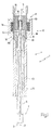
- Number 1 in Figure 1 indicates as a whole a fuel injector, which is cylindrically symmetrical about a longitudinal axis 2, and is controlled to inject fuel from an injection nozzle 3.
- Injector 1 comprises a cylindrical tubular supporting body 4 varying in section along longitudinal axis 2, and having a central channel 5 extending the full length of supporting body 4 to feed pressurized fuel to injection nozzle 3.
- Supporting body 4 houses an electromagnetic actuator 6 in a top portion, and an injection valve 7 in a bottom portion. In actual use, injection valve 7 is activated by electromagnetic actuator 6 to regulate fuel flow through injection nozzle 3, which is formed at injection valve 7.
- Supporting body 4 is formed by connection of a one-piece tubular top member 8, housing electromagnetic actuator 6, to a one-piece tubular bottom member 9, housing injection valve 7.
- Tubular top member 8 preferably comprises a cylindrical, internally threaded seat for receiving a threaded portion of tubular bottom member 9.
- Electromagnetic actuator 6 comprises an electromagnet 11 housed in a fixed position inside supporting body 4, and which, when excited, moves an armature 12 of ferromagnetic material along axis 2 from a closed position to an open position to open injection valve 7 in opposition to a spring 13 which keeps armature 12 in the closed position closing injection valve 7.
- Electromagnet 11 comprises a dry coil 14 powered electrically by an electronic control unit (not shown) and located outside supporting body 4; and a magnetic core 15 housed inside supporting body 4 and having a central hole 16 to permit fuel flow to injection nozzle 3.
- a cylindrical tubular retaining body 17 is fitted in a fixed position inside central hole 16 in magnetic core 15 to permit fuel flow to injection nozzle 3 and to keep spring 13 pressed against armature 12.
- Magnetic core 15 is preferably connected to supporting body 4 by an annular weld inside supporting body 4.
- Coil 14 of electromagnet 11 is housed inside a tubular seating body 18, which is closed at the bottom, surrounds supporting body 4, and is welded to supporting body 4 by an annular weld. At the top, seating body 18 is closed by an annular plug 19 welded to seating body 18 to isolate coil 14 inside seating body 18. It is important to note that, by virtue of its location, coil 14 dissipates considerable heat, and is isolated from the fuel and so unaffected by the mechanical effect and chemical aggression produced by the pressurized fuel.
- Armature 12 forms part of a movable assembly, which also comprises a shutter or pin 20 having a top portion integral with armature 12, and a bottom portion cooperating with a valve seat 21 (Figure 2) of injection valve 7 to regulate fuel flow through injection nozzle 3 in known manner.
- a shutter or pin 20 having a top portion integral with armature 12, and a bottom portion cooperating with a valve seat 21 ( Figure 2) of injection valve 7 to regulate fuel flow through injection nozzle 3 in known manner.
- valve seat 21 is defined by a disk-shaped sealing member 22, which closes the bottom of central channel 5 of supporting body 4 in fluidtight manner, and through which injection nozzle 3 extends.
- a tubular guide member 23 extends upwards from disk-shaped sealing member 22, houses pin 20 to define a bottom guide of pin 20, and has an outside diameter substantially equal to the inside diameter of central channel 5 of supporting body 4.
- Pin 20 terminates with a substantially spherical shutter head 24, which rests in fluidtight manner on valve seat 21.
- Shutter head 24 also rests in sliding manner against a cylindrical inner surface 25 of guide member 23, by which it is guided in its movement along longitudinal axis 2.
- Recesses 26 are formed in shutter head 24 to define, between each recess 26 and cylindrical inner surface 25 of guide member 23, a fuel flow passage to injection nozzle 3.
- injection nozzle 3 is defined by a number of through holes 27 extending from a hemispherical chamber 28 formed downstream from valve seat 21.
- armature 12 is a one-piece body, and comprises an annular member 29; and a disk-shaped member 30, which closes the underside of annular member 29, and in turn comprises a central through hole for receiving a top portion of pin 20, and a number of peripheral through holes (only two shown in Figure 1) to permit fuel flow to injection nozzle 3.
- a central portion of disk-shaped member 30 is shaped to receive and hold in position a bottom end of spring 13.
- Pin 20 is preferably made integral with disk-shaped member 30 of armature 12 by an annular weld.
- annular member 29 of armature 12 is substantially equal to the inside diameter of the corresponding portion of central channel 5 of supporting body 4, so that armature 12 can slide with respect to supporting body 4 along longitudinal axis 2, but is prevented from moving crosswise to longitudinal axis 2 with respect to supporting body 4.
- Pin 20 being connected rigidly to armature 12, armature 12 therefore also acts as a top guide for pin 20, which is therefore guided at the top by armature 12 and at the bottom by guide member 23.
- a bounce-damping device is connected to the underside face of disk-shaped member 30 of armature 12 to reduce bounce of shutter head 24 of pin 20 on valve seat 21 when pin 20 moves from the open position to the closed position closing injection valve 7.
- tubular bottom member 9 is much longer than tubular top member 8, and houses almost the whole of pin 20, which is the mechanical member responsible for opening and closing injection valve 7.
- pin 20 is the mechanical member responsible for opening and closing injection valve 7.
- both tubular bottom member 9 and pin 20 are made of a low-thermal-expansion alloy, in particular INVAR 36.
- Cylindrical sleeve 10 performs purely mechanical functions, to relieve tubular bottom member 9 of the axial and transverse loads to which injector 1 is subjected in use, and is therefore made of ordinary stainless steel.
- Tubular top member 8 is preferably made of high-tensile stainless steel with poor magnetic characteristics (i.e. nonmagnetic, and therefore of low magnetic permeability comparable to that of air).
- An iron-cobalt alloy such as hardened and tempered ISI 440C, may be used, for example.
- Seating body 18, annular plug 19, magnetic core 15, and armature 12 (or at least tubular member 9 of armature 12) are made of magnetic stainless steel (i.e. with a much higher magnetic permeability than air), such as VACUFLUX 50.
- supporting body 4 is formed in one piece and made entirely of high-tensile stainless steel with poor magnetic characteristics.
- Injector 1 as described above is cheap and easy to produce, by being formed by connecting a small number of parts, each of which is cylindrically symmetrical and therefore easy to produce by means of standard, easily automated turning operations involving no dedicated tooling. Moreover, simulation and testing have shown injector 1 as described above to be capable of operating at very high fuel pressures (close to 1000 bars) while still maintaining excellent dynamic performance (i.e. precise injection times).
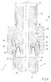
- supporting body 4 of injector 1 is connected to a pressurized-fuel feed conduit 31 by means of a connector 32. More specifically, supporting body 4 is connected in fluidtight manner to feed conduit 31 to connect central channel 5 of supporting body 4 hydraulically to feed conduit 31.
- Connector 32 is cylindrically symmetrical about longitudinal axis 2, and comprises a cylindrical top member 33, which is substantially equal in outside diameter to the inside diameter of feed conduit 31, and has a threaded outer end portion which screws inside feed conduit 31.
- Connector 32 also comprises a central member 34 larger in outside diameter than top member 33 and terminating with a truncated-cone-shaped surface 35; and a cylindrical bottom member 36 smaller in outside diameter than the inside diameter of central channel 5 of supporting body 4, and which is located inside central channel 5.
- the top end of supporting body 4 has a truncated-cone-shaped surface 37, which is positioned contacting truncated-cone-shaped surface 35 of central member 34 of connector 32.
- annular fastening member 38 is screwed to a threaded outer surface 39 of supporting body 4 so as to contact, with a given pressure, an annular top surface 40 of central member 34 of connector 32.
- annular seal 43 is fitted between an outer surface 41 of bottom member 36 and an inner surface 42 of central channel 5.
- bottom member 36 terminates with an annular enlargement 44 for retaining seal 43 on bottom member 36 during assembly.
- annular seal 43 is an O-ring seal made of elastic polymer material and having a solid oval-shaped cross section.
- annular seal 43 is a lip seal made of elastic polymer material and having a partly hollow, inverted-U-shaped cross section.
- An annular, inverted-U-shaped spring 45 is preferably inserted inside annular lip seal 43, and may be made of metal or elastomer.
- Connector 32 as described above provides for ensuring long-term sealing, even in the presence of continuous vibration, and is cheap and easy to produce, by the component parts not requiring particularly accurate machining.
Landscapes
- Engineering & Computer Science (AREA)
- Chemical & Material Sciences (AREA)
- Combustion & Propulsion (AREA)
- Mechanical Engineering (AREA)
- General Engineering & Computer Science (AREA)
- Physics & Mathematics (AREA)
- Electromagnetism (AREA)
- Fuel-Injection Apparatus (AREA)
Priority Applications (1)
| Application Number | Priority Date | Filing Date | Title |
|---|---|---|---|
| EP07114744A EP1852602B1 (fr) | 2004-07-23 | 2005-07-22 | Injecteur de carburant à commande électromagnétique |
Applications Claiming Priority (1)
| Application Number | Priority Date | Filing Date | Title |
|---|---|---|---|
| IT000466A ITBO20040466A1 (it) | 2004-07-23 | 2004-07-23 | Iniettore di carburante con attuazione elettromagnetica |
Related Child Applications (1)
| Application Number | Title | Priority Date | Filing Date |
|---|---|---|---|
| EP07114744A Division EP1852602B1 (fr) | 2004-07-23 | 2005-07-22 | Injecteur de carburant à commande électromagnétique |
Publications (3)
| Publication Number | Publication Date |
|---|---|
| EP1619383A2 true EP1619383A2 (fr) | 2006-01-25 |
| EP1619383A3 EP1619383A3 (fr) | 2006-04-12 |
| EP1619383B1 EP1619383B1 (fr) | 2007-11-28 |
Family
ID=34979616
Family Applications (2)
| Application Number | Title | Priority Date | Filing Date |
|---|---|---|---|
| EP07114744A Expired - Lifetime EP1852602B1 (fr) | 2004-07-23 | 2005-07-22 | Injecteur de carburant à commande électromagnétique |
| EP05106773A Expired - Lifetime EP1619383B1 (fr) | 2004-07-23 | 2005-07-22 | Injecteur de carburant actionné par un electro aimant |
Family Applications Before (1)
| Application Number | Title | Priority Date | Filing Date |
|---|---|---|---|
| EP07114744A Expired - Lifetime EP1852602B1 (fr) | 2004-07-23 | 2005-07-22 | Injecteur de carburant à commande électromagnétique |
Country Status (8)
| Country | Link |
|---|---|
| US (1) | US7438242B2 (fr) |
| EP (2) | EP1852602B1 (fr) |
| JP (1) | JP4741308B2 (fr) |
| CN (2) | CN100523475C (fr) |
| AT (1) | ATE435370T1 (fr) |
| DE (2) | DE602005003513T2 (fr) |
| ES (2) | ES2297623T3 (fr) |
| IT (1) | ITBO20040466A1 (fr) |
Cited By (7)
| Publication number | Priority date | Publication date | Assignee | Title |
|---|---|---|---|---|
| EP1843038A1 (fr) * | 2006-04-07 | 2007-10-10 | Siemens Aktiengesellschaft | Injecteur de carburant avec boitier à surfaces d'étanchéité coniques haute pression |
| EP1936181A1 (fr) * | 2006-12-12 | 2008-06-25 | MAGNETI MARELLI POWERTRAIN S.p.A. | Injecteur de carburant électromagnetique pour un moteur à combustion interne avec injection directe |
| DE102008006197A1 (de) * | 2008-01-26 | 2009-07-30 | Man Diesel Se | Kraftstoffversorgungsanlage einer Brennkraftmaschine |
| WO2010081583A1 (fr) * | 2009-01-13 | 2010-07-22 | Robert Bosch Gmbh | Soupape d'injection de combustible |
| WO2010106149A1 (fr) * | 2009-03-19 | 2010-09-23 | Delphi Technologies, Inc. | Agencement d'actionneur |
| EP2330288A1 (fr) * | 2009-11-23 | 2011-06-08 | Robert Bosch GmbH | Soupape d'injection de combustible |
| EP3208456A1 (fr) * | 2016-02-16 | 2017-08-23 | Delphi International Operations Luxembourg S.à r.l. | Ensemble de buse et injecteur de carburant |
Families Citing this family (10)
| Publication number | Priority date | Publication date | Assignee | Title |
|---|---|---|---|---|
| EP1760306A1 (fr) * | 2005-09-06 | 2007-03-07 | Siemens Aktiengesellschaft | Corps de boîte |
| DE102006052817A1 (de) * | 2006-11-09 | 2008-05-15 | Robert Bosch Gmbh | Brennstoffeinspritzventil |
| US7658631B2 (en) * | 2007-06-25 | 2010-02-09 | Caterpillar Inc. | Four wire elastomeric seal and fuel injector using same |
| EP2221468A1 (fr) * | 2009-02-20 | 2010-08-25 | Continental Automotive GmbH | Injecteur de fluide |
| CN103277224B (zh) * | 2013-06-08 | 2015-11-25 | 苏州柏德纳科技有限公司 | 一种具有压紧装置的喷油器 |
| DE102013018108B4 (de) * | 2013-12-03 | 2015-08-06 | Carl Freudenberg Kg | Dichtung |
| CN107613891B (zh) * | 2014-04-18 | 2021-12-14 | 贝克顿·迪金森公司 | 用于导管的针拘限安全互锁 |
| DE102015226769A1 (de) * | 2015-12-29 | 2017-06-29 | Robert Bosch Gmbh | Brennstoffeinspritzventil |
| US9915389B1 (en) * | 2017-02-06 | 2018-03-13 | Emerson Process Management Regulator Technologies, Inc. | Mechanically-retained sealing disks for use with fluid regulators |
| GB2615372B (en) * | 2022-02-03 | 2024-02-28 | Delphi Tech Ip Ltd | Fuel injector |
Citations (4)
| Publication number | Priority date | Publication date | Assignee | Title |
|---|---|---|---|---|
| EP0921302A2 (fr) | 1997-12-06 | 1999-06-09 | LUCAS INDUSTRIES public limited company | Injecteur de combustible |
| US6027050A (en) | 1996-06-22 | 2000-02-22 | Robert Bosch Gmbh | Injection valve in particular for directly injecting fuel into the combustion chamber of an internal combustion engine |
| EP1036932A2 (fr) | 1999-03-18 | 2000-09-20 | Delphi Technologies, Inc. | Injecteur de carburant |
| WO2001029395A2 (fr) | 1999-10-22 | 2001-04-26 | Robert Bosch Gmbh | Dispositif de commande hydraulique, en particulier pour un injecteur |
Family Cites Families (21)
| Publication number | Priority date | Publication date | Assignee | Title |
|---|---|---|---|---|
| GB269735A (en) * | 1925-11-09 | 1927-04-11 | Lorenz Konrad Braren | Improvements in or relating to fuel lines for internal combustion engines |
| GB2107809A (en) * | 1981-10-16 | 1983-05-05 | Rolls Royce | Fuel pipe seal |
| JPS60212669A (ja) * | 1984-04-05 | 1985-10-24 | Nippon Denso Co Ltd | アキユムレ−タ型燃料噴射ノズル |
| JP2508744B2 (ja) * | 1987-08-11 | 1996-06-19 | 日本電装株式会社 | 燃料噴射装置用電磁弁 |
| DE4111772A1 (de) * | 1991-04-11 | 1992-10-15 | Kloeckner Humboldt Deutz Ag | Ansaugsystem fuer eine selbstzuendende brennkraftmaschine |
| US5372313A (en) * | 1993-02-16 | 1994-12-13 | Siemens Automotive L.P. | Fuel injector |
| ITBO940223A1 (it) * | 1994-05-18 | 1995-11-18 | Weber Srl | Iniettore ad alta capacita' di atomizzazione |
| JPH0828393A (ja) * | 1994-07-19 | 1996-01-30 | Hitachi Ltd | 電磁式燃料噴射弁 |
| JPH08177689A (ja) * | 1994-12-28 | 1996-07-12 | Nippon Soken Inc | 内燃機関の燃料供給装置 |
| JP3687125B2 (ja) * | 1995-03-08 | 2005-08-24 | 株式会社デンソー | 内燃機関用燃料噴射ノズル |
| DE19631280A1 (de) * | 1996-08-02 | 1998-02-05 | Bosch Gmbh Robert | Brennstoffeinspritzventil und Verfahren zur Herstellung |
| US6484700B1 (en) * | 2000-08-24 | 2002-11-26 | Synerject, Llc | Air assist fuel injectors |
| US6302337B1 (en) * | 2000-08-24 | 2001-10-16 | Synerject, Llc | Sealing arrangement for air assist fuel injectors |
| DE10049034B4 (de) * | 2000-10-04 | 2005-08-04 | Robert Bosch Gmbh | Brennstoffeinspritzventil |
| US6755360B1 (en) * | 2001-03-01 | 2004-06-29 | Brunswick Corporation | Fuel injector with an improved poppet which is increasingly comformable to a valve seat in response to use |
| US6764028B2 (en) * | 2001-04-04 | 2004-07-20 | Synerject, Llc | Fuel injector nozzles |
| DE10130208A1 (de) * | 2001-06-22 | 2003-01-02 | Bosch Gmbh Robert | Brennstoffeinspritzventil |
| US6851622B2 (en) * | 2002-01-08 | 2005-02-08 | Siemens Vdo Automotive Corporation | Fuel injector having a ferromagnetic coil bobbin |
| US7252249B2 (en) * | 2002-02-22 | 2007-08-07 | Delphi Technologies, Inc. | Solenoid-type fuel injector assembly having stabilized ferritic stainless steel components |
| JP4120632B2 (ja) * | 2004-01-22 | 2008-07-16 | 株式会社デンソー | 燃料噴射弁 |
| ITBO20040560A1 (it) * | 2004-09-10 | 2004-12-10 | Magneti Marelli Powertrain Spa | Iniettore di carburante con valvola di iniezione provvista di alimentazione laterale |
-
2004
- 2004-07-23 IT IT000466A patent/ITBO20040466A1/it unknown
-
2005
- 2005-07-22 EP EP07114744A patent/EP1852602B1/fr not_active Expired - Lifetime
- 2005-07-22 AT AT07114744T patent/ATE435370T1/de not_active IP Right Cessation
- 2005-07-22 ES ES05106773T patent/ES2297623T3/es not_active Expired - Lifetime
- 2005-07-22 DE DE602005003513T patent/DE602005003513T2/de not_active Expired - Lifetime
- 2005-07-22 ES ES07114744T patent/ES2328643T3/es not_active Expired - Lifetime
- 2005-07-22 EP EP05106773A patent/EP1619383B1/fr not_active Expired - Lifetime
- 2005-07-22 US US11/188,224 patent/US7438242B2/en not_active Expired - Fee Related
- 2005-07-22 DE DE602005015259T patent/DE602005015259D1/de not_active Expired - Lifetime
- 2005-07-25 JP JP2005214067A patent/JP4741308B2/ja not_active Expired - Fee Related
- 2005-07-25 CN CNB2005100855918A patent/CN100523475C/zh not_active Expired - Fee Related
- 2005-07-25 CN CN200810188872XA patent/CN101598092B/zh not_active Expired - Fee Related
Patent Citations (4)
| Publication number | Priority date | Publication date | Assignee | Title |
|---|---|---|---|---|
| US6027050A (en) | 1996-06-22 | 2000-02-22 | Robert Bosch Gmbh | Injection valve in particular for directly injecting fuel into the combustion chamber of an internal combustion engine |
| EP0921302A2 (fr) | 1997-12-06 | 1999-06-09 | LUCAS INDUSTRIES public limited company | Injecteur de combustible |
| EP1036932A2 (fr) | 1999-03-18 | 2000-09-20 | Delphi Technologies, Inc. | Injecteur de carburant |
| WO2001029395A2 (fr) | 1999-10-22 | 2001-04-26 | Robert Bosch Gmbh | Dispositif de commande hydraulique, en particulier pour un injecteur |
Cited By (13)
| Publication number | Priority date | Publication date | Assignee | Title |
|---|---|---|---|---|
| EP1843038A1 (fr) * | 2006-04-07 | 2007-10-10 | Siemens Aktiengesellschaft | Injecteur de carburant avec boitier à surfaces d'étanchéité coniques haute pression |
| EP1936181A1 (fr) * | 2006-12-12 | 2008-06-25 | MAGNETI MARELLI POWERTRAIN S.p.A. | Injecteur de carburant électromagnetique pour un moteur à combustion interne avec injection directe |
| US7850100B2 (en) | 2006-12-12 | 2010-12-14 | Magneti Marelli Powertrain S.P.A. | Electromagnetic fuel injector for a direct injection internal combustion engine |
| CN101498265B (zh) * | 2008-01-26 | 2013-07-17 | 曼柴油机欧洲股份公司 | 内燃机的燃料供应设备 |
| DE102008006197A1 (de) * | 2008-01-26 | 2009-07-30 | Man Diesel Se | Kraftstoffversorgungsanlage einer Brennkraftmaschine |
| DE102008006197B4 (de) | 2008-01-26 | 2020-06-04 | Man Energy Solutions Se | Kraftstoffversorgungsanlage einer Brennkraftmaschine |
| US9103310B2 (en) | 2009-01-13 | 2015-08-11 | Robert Bosch Gmbh | Fuel injector |
| WO2010081583A1 (fr) * | 2009-01-13 | 2010-07-22 | Robert Bosch Gmbh | Soupape d'injection de combustible |
| CN102356230A (zh) * | 2009-03-19 | 2012-02-15 | 德尔福技术控股有限公司 | 致动器装置 |
| WO2010106149A1 (fr) * | 2009-03-19 | 2010-09-23 | Delphi Technologies, Inc. | Agencement d'actionneur |
| US9127633B2 (en) | 2009-03-19 | 2015-09-08 | Delphi International Operations Luxembourg S.A.R.L. | Actuator arrangement |
| EP2330288A1 (fr) * | 2009-11-23 | 2011-06-08 | Robert Bosch GmbH | Soupape d'injection de combustible |
| EP3208456A1 (fr) * | 2016-02-16 | 2017-08-23 | Delphi International Operations Luxembourg S.à r.l. | Ensemble de buse et injecteur de carburant |
Also Published As
| Publication number | Publication date |
|---|---|
| CN100523475C (zh) | 2009-08-05 |
| DE602005003513T2 (de) | 2008-10-23 |
| ATE435370T1 (de) | 2009-07-15 |
| ES2297623T3 (es) | 2008-05-01 |
| CN101598092A (zh) | 2009-12-09 |
| ES2328643T3 (es) | 2009-11-16 |
| JP4741308B2 (ja) | 2011-08-03 |
| ITBO20040466A1 (it) | 2004-10-23 |
| EP1852602B1 (fr) | 2009-07-01 |
| US7438242B2 (en) | 2008-10-21 |
| JP2006037958A (ja) | 2006-02-09 |
| DE602005015259D1 (de) | 2009-08-13 |
| US20060022072A1 (en) | 2006-02-02 |
| EP1619383B1 (fr) | 2007-11-28 |
| DE602005003513D1 (de) | 2008-01-10 |
| CN1757903A (zh) | 2006-04-12 |
| CN101598092B (zh) | 2011-03-30 |
| EP1852602A1 (fr) | 2007-11-07 |
| EP1619383A3 (fr) | 2006-04-12 |
Similar Documents
| Publication | Publication Date | Title |
|---|---|---|
| US7438242B2 (en) | Electromagnetically actuated fuel injector | |
| CN101490403B (zh) | 具有压力平衡的控制阀的燃料喷射器 | |
| EP1619384B1 (fr) | Injecteur de carburant comportant une aiguille de grande flexibilité | |
| CN102893016B (zh) | 电磁式燃料喷射阀 | |
| EP0604914A1 (fr) | Soupape électromagnétique de dosage d'un injecteur de combustible | |
| CN1776214B (zh) | 带有柱塞电磁激励的燃料喷射器 | |
| US6601784B2 (en) | Flexural element for positioning an armature in a fuel injector | |
| US7204434B2 (en) | Fuel injector | |
| US7191963B2 (en) | Fuel injector with hydraulic pin actuation | |
| JP7280439B2 (ja) | 燃料噴射弁のプレストローク調整方法 | |
| EP2631465A1 (fr) | Soupape à solénoïde | |
| US6953183B2 (en) | Proportional solenoid valve | |
| KR20100117091A (ko) | 밸브 조립체 및 조립 방법 | |
| JP2013167194A (ja) | 燃料噴射弁 | |
| US20250243829A1 (en) | Gas fuel injector | |
| CN100441857C (zh) | 喷射阀上设置有侧向进料孔的燃料喷射器 | |
| EP4474634A1 (fr) | Injecteur de carburant gazeux | |
| CN101560935B (zh) | 阀门片直接致动的、用于内燃发动机的燃料喷射器 | |
| JP2007170183A (ja) | 電磁式燃料噴射弁 | |
| JP4285466B2 (ja) | 電磁弁 | |
| US6913206B2 (en) | Fuel injector for an internal combustion engine with hydraulic pin actuation | |
| KR20230021603A (ko) | 기체 연료용 가스 계량공급 밸브 | |
| JP2008025651A (ja) | 電磁弁及びその製造方法 | |
| JP2010276002A (ja) | 燃料噴射弁 |
Legal Events
| Date | Code | Title | Description |
|---|---|---|---|
| PUAI | Public reference made under article 153(3) epc to a published international application that has entered the european phase |
Free format text: ORIGINAL CODE: 0009012 |
|
| AK | Designated contracting states |
Kind code of ref document: A2 Designated state(s): AT BE BG CH CY CZ DE DK EE ES FI FR GB GR HU IE IS IT LI LT LU LV MC NL PL PT RO SE SI SK TR |
|
| AX | Request for extension of the european patent |
Extension state: AL BA HR MK YU |
|
| PUAL | Search report despatched |
Free format text: ORIGINAL CODE: 0009013 |
|
| AK | Designated contracting states |
Kind code of ref document: A3 Designated state(s): AT BE BG CH CY CZ DE DK EE ES FI FR GB GR HU IE IS IT LI LT LU LV MC NL PL PT RO SE SI SK TR |
|
| AX | Request for extension of the european patent |
Extension state: AL BA HR MK YU |
|
| RIC1 | Information provided on ipc code assigned before grant |
Ipc: F02M 55/02 20060101ALI20060223BHEP Ipc: F02M 61/10 20060101ALI20060223BHEP Ipc: F02M 51/06 20060101AFI20051114BHEP Ipc: F02M 61/16 20060101ALI20060223BHEP |
|
| 17P | Request for examination filed |
Effective date: 20061004 |
|
| 17Q | First examination report despatched |
Effective date: 20061102 |
|
| AKX | Designation fees paid |
Designated state(s): AT BE BG CH CY CZ DE DK EE ES FI FR GB GR HU IE IS IT LI LT LU LV MC NL PL PT RO SE SI SK TR |
|
| GRAP | Despatch of communication of intention to grant a patent |
Free format text: ORIGINAL CODE: EPIDOSNIGR1 |
|
| GRAS | Grant fee paid |
Free format text: ORIGINAL CODE: EPIDOSNIGR3 |
|
| GRAA | (expected) grant |
Free format text: ORIGINAL CODE: 0009210 |
|
| AK | Designated contracting states |
Kind code of ref document: B1 Designated state(s): AT BE BG CH CY CZ DE DK EE ES FI FR GB GR HU IE IS IT LI LT LU LV MC NL PL PT RO SE SI SK TR |
|
| REG | Reference to a national code |
Ref country code: GB Ref legal event code: FG4D |
|
| REG | Reference to a national code |
Ref country code: IE Ref legal event code: FG4D |
|
| REG | Reference to a national code |
Ref country code: CH Ref legal event code: EP |
|
| REF | Corresponds to: |
Ref document number: 602005003513 Country of ref document: DE Date of ref document: 20080110 Kind code of ref document: P |
|
| REG | Reference to a national code |
Ref country code: SE Ref legal event code: TRGR |
|
| PG25 | Lapsed in a contracting state [announced via postgrant information from national office to epo] |
Ref country code: LI Free format text: LAPSE BECAUSE OF FAILURE TO SUBMIT A TRANSLATION OF THE DESCRIPTION OR TO PAY THE FEE WITHIN THE PRESCRIBED TIME-LIMIT Effective date: 20071128 Ref country code: CH Free format text: LAPSE BECAUSE OF FAILURE TO SUBMIT A TRANSLATION OF THE DESCRIPTION OR TO PAY THE FEE WITHIN THE PRESCRIBED TIME-LIMIT Effective date: 20071128 Ref country code: NL Free format text: LAPSE BECAUSE OF FAILURE TO SUBMIT A TRANSLATION OF THE DESCRIPTION OR TO PAY THE FEE WITHIN THE PRESCRIBED TIME-LIMIT Effective date: 20071128 |
|
| NLV1 | Nl: lapsed or annulled due to failure to fulfill the requirements of art. 29p and 29m of the patents act | ||
| REG | Reference to a national code |
Ref country code: ES Ref legal event code: FG2A Ref document number: 2297623 Country of ref document: ES Kind code of ref document: T3 |
|
| PG25 | Lapsed in a contracting state [announced via postgrant information from national office to epo] |
Ref country code: BG Free format text: LAPSE BECAUSE OF FAILURE TO SUBMIT A TRANSLATION OF THE DESCRIPTION OR TO PAY THE FEE WITHIN THE PRESCRIBED TIME-LIMIT Effective date: 20080228 Ref country code: LV Free format text: LAPSE BECAUSE OF FAILURE TO SUBMIT A TRANSLATION OF THE DESCRIPTION OR TO PAY THE FEE WITHIN THE PRESCRIBED TIME-LIMIT Effective date: 20071128 Ref country code: PL Free format text: LAPSE BECAUSE OF FAILURE TO SUBMIT A TRANSLATION OF THE DESCRIPTION OR TO PAY THE FEE WITHIN THE PRESCRIBED TIME-LIMIT Effective date: 20071128 Ref country code: SI Free format text: LAPSE BECAUSE OF FAILURE TO SUBMIT A TRANSLATION OF THE DESCRIPTION OR TO PAY THE FEE WITHIN THE PRESCRIBED TIME-LIMIT Effective date: 20071128 Ref country code: FI Free format text: LAPSE BECAUSE OF FAILURE TO SUBMIT A TRANSLATION OF THE DESCRIPTION OR TO PAY THE FEE WITHIN THE PRESCRIBED TIME-LIMIT Effective date: 20071128 Ref country code: LT Free format text: LAPSE BECAUSE OF FAILURE TO SUBMIT A TRANSLATION OF THE DESCRIPTION OR TO PAY THE FEE WITHIN THE PRESCRIBED TIME-LIMIT Effective date: 20071128 Ref country code: IS Free format text: LAPSE BECAUSE OF FAILURE TO SUBMIT A TRANSLATION OF THE DESCRIPTION OR TO PAY THE FEE WITHIN THE PRESCRIBED TIME-LIMIT Effective date: 20080328 |
|
| REG | Reference to a national code |
Ref country code: CH Ref legal event code: PL |
|
| PG25 | Lapsed in a contracting state [announced via postgrant information from national office to epo] |
Ref country code: AT Free format text: LAPSE BECAUSE OF FAILURE TO SUBMIT A TRANSLATION OF THE DESCRIPTION OR TO PAY THE FEE WITHIN THE PRESCRIBED TIME-LIMIT Effective date: 20071128 |
|
| ET | Fr: translation filed | ||
| PG25 | Lapsed in a contracting state [announced via postgrant information from national office to epo] |
Ref country code: DK Free format text: LAPSE BECAUSE OF FAILURE TO SUBMIT A TRANSLATION OF THE DESCRIPTION OR TO PAY THE FEE WITHIN THE PRESCRIBED TIME-LIMIT Effective date: 20071128 Ref country code: CZ Free format text: LAPSE BECAUSE OF FAILURE TO SUBMIT A TRANSLATION OF THE DESCRIPTION OR TO PAY THE FEE WITHIN THE PRESCRIBED TIME-LIMIT Effective date: 20071128 |
|
| PG25 | Lapsed in a contracting state [announced via postgrant information from national office to epo] |
Ref country code: SK Free format text: LAPSE BECAUSE OF FAILURE TO SUBMIT A TRANSLATION OF THE DESCRIPTION OR TO PAY THE FEE WITHIN THE PRESCRIBED TIME-LIMIT Effective date: 20071128 Ref country code: RO Free format text: LAPSE BECAUSE OF FAILURE TO SUBMIT A TRANSLATION OF THE DESCRIPTION OR TO PAY THE FEE WITHIN THE PRESCRIBED TIME-LIMIT Effective date: 20071128 Ref country code: BE Free format text: LAPSE BECAUSE OF FAILURE TO SUBMIT A TRANSLATION OF THE DESCRIPTION OR TO PAY THE FEE WITHIN THE PRESCRIBED TIME-LIMIT Effective date: 20071128 |
|
| PG25 | Lapsed in a contracting state [announced via postgrant information from national office to epo] |
Ref country code: PT Free format text: LAPSE BECAUSE OF FAILURE TO SUBMIT A TRANSLATION OF THE DESCRIPTION OR TO PAY THE FEE WITHIN THE PRESCRIBED TIME-LIMIT Effective date: 20080428 |
|
| PLBE | No opposition filed within time limit |
Free format text: ORIGINAL CODE: 0009261 |
|
| STAA | Information on the status of an ep patent application or granted ep patent |
Free format text: STATUS: NO OPPOSITION FILED WITHIN TIME LIMIT |
|
| 26N | No opposition filed |
Effective date: 20080829 |
|
| PG25 | Lapsed in a contracting state [announced via postgrant information from national office to epo] |
Ref country code: GR Free format text: LAPSE BECAUSE OF FAILURE TO SUBMIT A TRANSLATION OF THE DESCRIPTION OR TO PAY THE FEE WITHIN THE PRESCRIBED TIME-LIMIT Effective date: 20080229 |
|
| PG25 | Lapsed in a contracting state [announced via postgrant information from national office to epo] |
Ref country code: MC Free format text: LAPSE BECAUSE OF NON-PAYMENT OF DUE FEES Effective date: 20080731 |
|
| PG25 | Lapsed in a contracting state [announced via postgrant information from national office to epo] |
Ref country code: EE Free format text: LAPSE BECAUSE OF FAILURE TO SUBMIT A TRANSLATION OF THE DESCRIPTION OR TO PAY THE FEE WITHIN THE PRESCRIBED TIME-LIMIT Effective date: 20071128 |
|
| PG25 | Lapsed in a contracting state [announced via postgrant information from national office to epo] |
Ref country code: CY Free format text: LAPSE BECAUSE OF FAILURE TO SUBMIT A TRANSLATION OF THE DESCRIPTION OR TO PAY THE FEE WITHIN THE PRESCRIBED TIME-LIMIT Effective date: 20071128 Ref country code: IE Free format text: LAPSE BECAUSE OF NON-PAYMENT OF DUE FEES Effective date: 20080722 |
|
| PG25 | Lapsed in a contracting state [announced via postgrant information from national office to epo] |
Ref country code: LU Free format text: LAPSE BECAUSE OF NON-PAYMENT OF DUE FEES Effective date: 20080722 Ref country code: HU Free format text: LAPSE BECAUSE OF FAILURE TO SUBMIT A TRANSLATION OF THE DESCRIPTION OR TO PAY THE FEE WITHIN THE PRESCRIBED TIME-LIMIT Effective date: 20080529 |
|
| PG25 | Lapsed in a contracting state [announced via postgrant information from national office to epo] |
Ref country code: TR Free format text: LAPSE BECAUSE OF FAILURE TO SUBMIT A TRANSLATION OF THE DESCRIPTION OR TO PAY THE FEE WITHIN THE PRESCRIBED TIME-LIMIT Effective date: 20071128 |
|
| PG25 | Lapsed in a contracting state [announced via postgrant information from national office to epo] |
Ref country code: IT Free format text: LAPSE BECAUSE OF NON-PAYMENT OF DUE FEES Effective date: 20080731 |
|
| PGFP | Annual fee paid to national office [announced via postgrant information from national office to epo] |
Ref country code: SE Payment date: 20110627 Year of fee payment: 7 |
|
| PGFP | Annual fee paid to national office [announced via postgrant information from national office to epo] |
Ref country code: GB Payment date: 20110701 Year of fee payment: 7 Ref country code: ES Payment date: 20110715 Year of fee payment: 7 |
|
| REG | Reference to a national code |
Ref country code: SE Ref legal event code: EUG |
|
| GBPC | Gb: european patent ceased through non-payment of renewal fee |
Effective date: 20120722 |
|
| PG25 | Lapsed in a contracting state [announced via postgrant information from national office to epo] |
Ref country code: SE Free format text: LAPSE BECAUSE OF NON-PAYMENT OF DUE FEES Effective date: 20120723 Ref country code: GB Free format text: LAPSE BECAUSE OF NON-PAYMENT OF DUE FEES Effective date: 20120722 |
|
| REG | Reference to a national code |
Ref country code: ES Ref legal event code: FD2A Effective date: 20131021 |
|
| PG25 | Lapsed in a contracting state [announced via postgrant information from national office to epo] |
Ref country code: ES Free format text: LAPSE BECAUSE OF NON-PAYMENT OF DUE FEES Effective date: 20120723 |
|
| PGFP | Annual fee paid to national office [announced via postgrant information from national office to epo] |
Ref country code: DE Payment date: 20140620 Year of fee payment: 10 |
|
| PGFP | Annual fee paid to national office [announced via postgrant information from national office to epo] |
Ref country code: FR Payment date: 20140721 Year of fee payment: 10 |
|
| REG | Reference to a national code |
Ref country code: DE Ref legal event code: R119 Ref document number: 602005003513 Country of ref document: DE |
|
| PG25 | Lapsed in a contracting state [announced via postgrant information from national office to epo] |
Ref country code: DE Free format text: LAPSE BECAUSE OF NON-PAYMENT OF DUE FEES Effective date: 20160202 |
|
| REG | Reference to a national code |
Ref country code: FR Ref legal event code: ST Effective date: 20160331 |
|
| PG25 | Lapsed in a contracting state [announced via postgrant information from national office to epo] |
Ref country code: FR Free format text: LAPSE BECAUSE OF NON-PAYMENT OF DUE FEES Effective date: 20150731 |