EP1619695A2 - Ensemble de câbles avec moyens pour la prévention de la diaphonie - Google Patents
Ensemble de câbles avec moyens pour la prévention de la diaphonie Download PDFInfo
- Publication number
- EP1619695A2 EP1619695A2 EP05254371A EP05254371A EP1619695A2 EP 1619695 A2 EP1619695 A2 EP 1619695A2 EP 05254371 A EP05254371 A EP 05254371A EP 05254371 A EP05254371 A EP 05254371A EP 1619695 A2 EP1619695 A2 EP 1619695A2
- Authority
- EP
- European Patent Office
- Prior art keywords
- utp
- cable assembly
- wire pairs
- utp cable
- assembly according
- Prior art date
- Legal status (The legal status is an assumption and is not a legal conclusion. Google has not performed a legal analysis and makes no representation as to the accuracy of the status listed.)
- Granted
Links
Images


Classifications
-
- H—ELECTRICITY
- H01—ELECTRIC ELEMENTS
- H01B—CABLES; CONDUCTORS; INSULATORS; SELECTION OF MATERIALS FOR THEIR CONDUCTIVE, INSULATING OR DIELECTRIC PROPERTIES
- H01B7/00—Insulated conductors or cables characterised by their form
- H01B7/40—Insulated conductors or cables characterised by their form with arrangements for facilitating mounting or securing
-
- H—ELECTRICITY
- H01—ELECTRIC ELEMENTS
- H01B—CABLES; CONDUCTORS; INSULATORS; SELECTION OF MATERIALS FOR THEIR CONDUCTIVE, INSULATING OR DIELECTRIC PROPERTIES
- H01B11/00—Communication cables or conductors
- H01B11/02—Cables with twisted pairs or quads
- H01B11/04—Cables with twisted pairs or quads with pairs or quads mutually positioned to reduce cross-talk
-
- H—ELECTRICITY
- H01—ELECTRIC ELEMENTS
- H01B—CABLES; CONDUCTORS; INSULATORS; SELECTION OF MATERIALS FOR THEIR CONDUCTIVE, INSULATING OR DIELECTRIC PROPERTIES
- H01B11/00—Communication cables or conductors
- H01B11/02—Cables with twisted pairs or quads
- H01B11/06—Cables with twisted pairs or quads with means for reducing effects of electromagnetic or electrostatic disturbances, e.g. screens
-
- H—ELECTRICITY
- H01—ELECTRIC ELEMENTS
- H01B—CABLES; CONDUCTORS; INSULATORS; SELECTION OF MATERIALS FOR THEIR CONDUCTIVE, INSULATING OR DIELECTRIC PROPERTIES
- H01B13/00—Apparatus or processes specially adapted for manufacturing conductors or cables
- H01B13/06—Insulating conductors or cables
- H01B13/18—Applying discontinuous insulation, e.g. discs, beads
- H01B13/20—Applying discontinuous insulation, e.g. discs, beads for concentric or coaxial cables
- H01B13/206—Applying discontinuous insulation, e.g. discs, beads for concentric or coaxial cables by forming a helical web
Definitions
- the present invention relates to an unshielded twisted pair (UTP) cable assembly, and specifically a UTP cable assembly having a structure capable of preventing cross talk between wire pairs to improve its transmission property.
- UTP unshielded twisted pair
- the UTP cable is an unshielded twisted pair widely used to construct a communication network such as LAN, which includes wire pairs (P), each having two insulator-coated wires 10, 11 twisted in a spiral manner as shown in Fig. 1.
- wire pairs P
- at least two cables C are assembled as a bundle as shown in Fig. 2.
- a conventional bundle-type UTP cable has a disadvantage of inducing alien cross talk that an electromagnetic field induced in wires of each single UTP cable gives electromagnetic influences on other adjacent UTP cables due to its structure that adjacent cables are contacted with each other.
- a conventional UTP cable assembly has a problem that the inherent pitch arranged in of a cable pair at opposite locations or the aggregated pitch of twisted wire pairs are designed to have the same length in each UTP cable, so the alien cross talk between the UTP cables becomes worse.
- a UTP cable arranged in the center of the cable assembly is severely electromagnetically affected from other cables in all directions, and such a severe electromagnetical influence acts as a noise in the signal transmission system, eventually causing a communication disorder.
- the present invention is designed to solve the problems of the prior art, and it is an object of the present invention to provide a UTP cable assembly having a structure capable of preventing the generation of cross talk between internal wire pairs of the UTP cable, adjacent to each other.
- the present invention provides a UTP (Unshielded Twisted Pair) cable assembly, which includes at least two UTP cables, in each of which wire pairs, each having two insulator-coated wires twisted in a spiral manner, are aggregated in a sheath; and a web member interposed between the UTP cables to interconnect the adjacent UTP cables and keep a space between the adjacent UTP cables, wherein the web member has a width of 0.2 mm to 2.0 mm.
- UTP Unshielded Twisted Pair
- a width of the web member functions to minimize cross talk between the UTP cables and to keep an optimum space therebetween. At this time, if the web member has an extremely small width, it is difficult to dismantle the UTP cable assembly, causing damage of the cables, while, if the web member has an extremely large width, it is difficult to keep an optimum space between the UTP cables. Accordingly, The width of the web member may be preferably set to the range of 0.2 mm to 2.0 mm, more preferably 0.8 mm to 1.2 mm.
- the wire pair has a minimum pitch value of about 8 mm and a maximum pitch value of about 20 mm to satisfy cross talk property and other properties in the 4-pair single UTP cable.
- the pitch values of the remaining two wire pairs in the 4-pair single UTP cable are further determined within the range between the maximum and minimum pitch values. Pitch combinations among four wire pairs in the single UTP cable determined as above thus satisfy electric properties of each single UTP cable.
- Each single UTP cable should satisfy electric properties even if a web member is interposed between the UTP cables to keep a space between at least two UTP cables.
- the wire pairs arranged in corresponding locations in the UTP cables preferably have different pitch values.
- the difference of the pitch values between the corresponding wire pairs preferably has a value of 0.2 mm or more.
- the difference of pitches between the four wire pairs is preferably 0.5 mm to 7.5 mm, more preferably 1.0 mm to 7.0 mm.
- a cross filler may be further inserted in the sheath of the UTP cable in a length direction to isolate the wire pairs from each other.
- the UTP cable assembly includes at least two UTP cables, in each of which wire pairs, each having two insulator-coated wires twisted in a spiral manner, are aggregated in a sheath; and a web member interposed between the UTP cables to interconnect the adjacent UTP cables and keep a space between the UTP cables and having a width of 0.2 mm to 2.0 mm, wherein the wire pairs in each UTP cable are twisted at regular aggregation pitches, and aggregation pitches of the adjacent UTP cable have different lengths.
- the aggregation pitch is preferably 50 mm to 200 mm, more preferably 70 mm to 150 mm.
- aggregation pitches of wire pairs in an odd number group or in an even number group preferably have the same length, respectively.
- a cross filler may be further inserted in the sheath of the UTP cable in a length direction to isolate the wire pairs from each other.
- the web member is preferably made of polyvinyl chloride (PVC) or low smoke zero halogen (LSZH) materials, with its width of 0.2 mm to 2.0 mm, more preferably 0.8 mm to 1.2 mm.
- PVC polyvinyl chloride
- LSZH low smoke zero halogen
- Fig. 3 is a cross sectional view showing a UTP cable assembly according to one embodiment of the present invention.
- the UTP cable assembly includes at least two UTP cables C1, C2, each having a plurality of wire pairs P1 to P8 therein, and a web member 103 interposed between adjacent UTP cables C1, C2.
- the order of the wire pairs P1 to P8 shows in each single UTP cable P1 ⁇ P4 and P5 ⁇ P8 that P1 and P5 correspond to the shortest pitches and P4 and P8 correspond to the longest pitches, respectively. And, the order of their lengths is applied to every single UTP cable identically.
- the UTP cable C1, C2 is configured so that a plurality of wire pairs P1 to P8, each having two insulator-coated wires 100 and 101 twisted in a spiral manner, are aggregated in a sheath 102.
- the web member 103 is interposed between the UTP cables C1, C2 to connect the adjacent UTP cables C1, C2 to each other.
- the web member 103 also keeps a space between the UTP cables C1, C2 so as to prevent alien cross talk.
- the web member 103 has a web structure easily torn to facilitate dismantling operation of the cable, and is preferably formed of polyvinyl chloride (PVC) or low smoke zero halogen (LSZH) materials.
- PVC polyvinyl chloride
- LSZH low smoke zero halogen
- the shape of the web member 103 may be variously modified, not limited to one shown in the figures.
- the width W of the web member 103 may be preferably set to 0.2 mm to 2.0 mm, more preferably 0.8 mm to 1.2 mm, to keep an optimum space between the UTP cables C1, C2 and also to minimize the cross talk.
- the pitches of wire pairs arranged at the corresponding positions like P1 and P5, or P4 and P8, preferably have different lengths to minimize an electromagnetic interaction between the pairs.
- the difference of pitches between the corresponding wire pairs is preferably maintained to 0.2 mm or larger to prevent the electromagnetic interaction.
- the difference of pitches between the wire pairs is preferably maintained in the range of 0.5 mm to 7.5 mm, more preferably 1.0 mm to 7.0 mm, to minimize the electromagnetic interaction.
- the number of wire pairs is not limited to this embodiment but may be variously modified.
- a cross filler 104 is inserted in a length direction in the UTP cable C1, C2 having four wire pairs so as to isolate the wire pairs from each other and prevent the cross talk between the pairs.
- the cross filler 104 is provided with 4 bulkheads crossing with each other so as to bar interaction between the wire pairs.
- the aggregation pitches of wire pairs in an odd number group or in an even number group preferably have same length.
- the wire pairs in the UTP cables C1, C2 may be aggregated with being twisted with each other at regular aggregation pitches. That is to say, the UTP cable C1 is configured so that the wire pairs P1 to P4 are spirally twisted with each other at regular aggregation pitches, and the UTP cable C2 is configured so that the wire pairs P5 to P8 are spirally twisted with each other at regular aggregation pitches.
- the aggregation pitches of the UTP cables C1 and C2 preferably have different lengths to prevent the cross talk between the wire pairs. It is because that the electromagnetic interaction is inversely proportional to the distance between the wires.
- the aggregation pitches of the wire pairs are identical to each other, the space between the corresponding pairs of the respective UTP cables are kept regularly, which may maximize influence of the alien cross talk between the pairs.
- the aggregation pitches of the UTP cables C1, C2 may be set in the range of 50 mm to 200 mm, more preferably 70 mm to 150 mm, for more effective prevention-of the cross talk.
- the web member is interposed between the UTP cables to connect the adjacent UTP cables to each other, and simultaneously to prevent alien cross talk with keeping a space between the UTP cables.
- the web member has a web structure easily torn to facilitate dismantling operation of the cable, and is preferably formed of polyvinyl chloride (PVC) or low smoke zero halogen (LSZH) materials.
- PVC polyvinyl chloride
- LSZH low smoke zero halogen
- the shape of the web member may be variously modified, not limited to one shown in the figures.
- the width W of the web member 103 may be preferably set to 0.2 mm to 2.0 mm, more preferably 0.8 mm to 1.2 mm, to keep an optimum space between the UTP cables and also to minimize the cross talk.
- Fig. 4 shows an embodiment where four UTP cables C1 to C4 are connected in series. If at least 4 UTP cables are connected in series as shown in Fig. 4, respective pitches and aggregation pitches of the wire pairs in an odd number cable group (see C 1 and C3) or in an even number cable group (see C2 and C4) have the same lengths, while the pitches in adjacent cable groups preferably have different lengths to prevent the cross talk between the wire pairs P1 to P16.
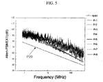
- Fig. 5 shows an embodiment to which conditions for keeping a regular space between UTP cables and conditions for optimizing their pitches as mentioned above are applied.
- a regulated value P20 of the alien cross talk regulated in IEC61156-5 and a measurement value of each cable are depicted.
- UTP cables are interconnected with an optimum space by means of the web member 103, so the wire pairs of adjacent UTP cables are not electromagnetically affected from each other and therefore the alien cross talk is prevented.
- the present invention may prevent the generation of alien cross talk between wire pairs and allow manufacture of standardized UTP cable assemblies because a space between the UTP cables may be kept optimally.
- the present invention ensures easy dismantling of cables under construction since UTP cables keep a constant space by means of a web structure that is easily torn.
- the present invention may provide a UTP cable assembly having optimized pitch conditions to minimize electromagnetic interaction between wire pairs.
- the present invention as mentioned above may be very usefully used for a 10-gigabit transmission network as a signal transmission system of a communication cable using copper, which requires prevention of alien cross talk.
Landscapes
- Physics & Mathematics (AREA)
- Electromagnetism (AREA)
- Engineering & Computer Science (AREA)
- Manufacturing & Machinery (AREA)
- Communication Cables (AREA)
Applications Claiming Priority (1)
| Application Number | Priority Date | Filing Date | Title |
|---|---|---|---|
| KR1020040057351A KR100603087B1 (ko) | 2004-07-22 | 2004-07-22 | 크로스토크 방지수단을 구비한 utp 케이블 어셈블리 |
Publications (3)
| Publication Number | Publication Date |
|---|---|
| EP1619695A2 true EP1619695A2 (fr) | 2006-01-25 |
| EP1619695A3 EP1619695A3 (fr) | 2009-04-08 |
| EP1619695B1 EP1619695B1 (fr) | 2015-01-14 |
Family
ID=35134567
Family Applications (1)
| Application Number | Title | Priority Date | Filing Date |
|---|---|---|---|
| EP05254371.7A Expired - Lifetime EP1619695B1 (fr) | 2004-07-22 | 2005-07-13 | Ensemble de câbles avec moyens pour la prévention de la diaphonie |
Country Status (2)
| Country | Link |
|---|---|
| EP (1) | EP1619695B1 (fr) |
| KR (1) | KR100603087B1 (fr) |
Cited By (4)
| Publication number | Priority date | Publication date | Assignee | Title |
|---|---|---|---|---|
| WO2009074102A1 (fr) * | 2007-12-13 | 2009-06-18 | Huawei Technologies Co., Ltd. | Câble de communication, système, armoire et procédé de combinaison pour paires torsadées dans un câble de communication |
| US8818156B2 (en) | 2010-03-30 | 2014-08-26 | Corning Cable Systems Llc | Multiple channel optical fiber furcation tube and cable assembly using same |
| WO2015158421A1 (fr) * | 2014-04-16 | 2015-10-22 | Rosenberger Hochfrequenztechnik Gmbh & Co. Kg | Ensemble de câbles |
| CN114360800A (zh) * | 2021-11-29 | 2022-04-15 | 安徽华通电缆集团有限公司 | 一种机器人专用超高速柔性双绞屏蔽抗扭转电缆 |
Families Citing this family (7)
| Publication number | Priority date | Publication date | Assignee | Title |
|---|---|---|---|---|
| US7550674B2 (en) | 2007-02-22 | 2009-06-23 | Nexans | UTP cable |
| KR100951051B1 (ko) | 2007-05-17 | 2010-04-05 | 엘에스전선 주식회사 | 고속 통신용 케이블 |
| KR200450912Y1 (ko) | 2008-07-11 | 2010-11-09 | 황영식 | 유티피케이블 |
| KR100989323B1 (ko) * | 2008-08-14 | 2010-10-25 | 엘에스전선 주식회사 | 유티피 케이블 |
| KR20140100534A (ko) | 2011-12-06 | 2014-08-14 | 제너럴 케이블 테크놀로지즈 코오포레이션 | 불연성 재료를 갖는 케이블 구성요소 |
| EP2795630A1 (fr) * | 2011-12-21 | 2014-10-29 | General Cable Technology Corp. | Câble ayant une couche barrière non inflammable |
| KR102346715B1 (ko) | 2019-10-25 | 2022-01-04 | 한재용 | 효율적인 매설이 가능한 집합형 연선케이블 |
Family Cites Families (9)
| Publication number | Priority date | Publication date | Assignee | Title |
|---|---|---|---|---|
| US4012577A (en) * | 1975-04-30 | 1977-03-15 | Spectra-Strip Corporation | Multiple twisted pair multi-conductor laminated cable |
| JP3495297B2 (ja) | 1999-09-03 | 2004-02-09 | 積水化学工業株式会社 | 配線ケーブル構造 |
| DE19948678A1 (de) * | 1999-10-04 | 2001-05-03 | Leoni Kabel Gmbh & Co Kg | Datenübertragungskabel und Herstellungsverfahren |
| JP2001351439A (ja) | 2000-06-02 | 2001-12-21 | Nishi Nippon Electric Wire & Cable Co Ltd | Lan・電話複合ケ−ブル及び縦幹線用lan・電話複合ケ−ブル |
| AU2002240456A1 (en) * | 2001-02-23 | 2002-09-12 | Commscope, Inc. Of North Carolina | Connecting web for cable applications |
| JP2003045237A (ja) | 2001-07-30 | 2003-02-14 | Yazaki Corp | 複合ケーブル |
| US20030106704A1 (en) * | 2001-12-06 | 2003-06-12 | Isley James A. | Electrical cable apparatus |
| US6770819B2 (en) * | 2002-02-12 | 2004-08-03 | Commscope, Properties Llc | Communications cables with oppositely twinned and bunched insulated conductors |
| KR100496452B1 (ko) * | 2002-11-18 | 2005-06-20 | 엘에스전선 주식회사 | 통신용 복합 케이블 |
-
2004
- 2004-07-22 KR KR1020040057351A patent/KR100603087B1/ko not_active Expired - Fee Related
-
2005
- 2005-07-13 EP EP05254371.7A patent/EP1619695B1/fr not_active Expired - Lifetime
Cited By (6)
| Publication number | Priority date | Publication date | Assignee | Title |
|---|---|---|---|---|
| WO2009074102A1 (fr) * | 2007-12-13 | 2009-06-18 | Huawei Technologies Co., Ltd. | Câble de communication, système, armoire et procédé de combinaison pour paires torsadées dans un câble de communication |
| CN101458979B (zh) * | 2007-12-13 | 2012-06-27 | 华为技术有限公司 | 通信电缆、系统、机柜和通信电缆中双绞线对的配合方法 |
| US8818156B2 (en) | 2010-03-30 | 2014-08-26 | Corning Cable Systems Llc | Multiple channel optical fiber furcation tube and cable assembly using same |
| WO2015158421A1 (fr) * | 2014-04-16 | 2015-10-22 | Rosenberger Hochfrequenztechnik Gmbh & Co. Kg | Ensemble de câbles |
| CN106165225A (zh) * | 2014-04-16 | 2016-11-23 | 罗森伯格高频技术有限及两合公司 | 电缆配置 |
| CN114360800A (zh) * | 2021-11-29 | 2022-04-15 | 安徽华通电缆集团有限公司 | 一种机器人专用超高速柔性双绞屏蔽抗扭转电缆 |
Also Published As
| Publication number | Publication date |
|---|---|
| KR100603087B1 (ko) | 2006-07-20 |
| EP1619695A3 (fr) | 2009-04-08 |
| KR20060009448A (ko) | 2006-02-01 |
| EP1619695B1 (fr) | 2015-01-14 |
Similar Documents
| Publication | Publication Date | Title |
|---|---|---|
| US9748020B2 (en) | Flex-resistant wire and wire harness | |
| EP1619695B1 (fr) | Ensemble de câbles avec moyens pour la prévention de la diaphonie | |
| US7922520B2 (en) | Cable connector including intermediary interconnection board | |
| JP5865481B2 (ja) | シールドスターカッドケーブル | |
| EP1818945B1 (fr) | Améliorations dans et concernant des câbles électriques | |
| CN101436450A (zh) | 多芯电缆结构 | |
| JP5228398B2 (ja) | 複合ケーブル | |
| US11083120B2 (en) | Braided electromagnetic interference protective sleeve and method of construction thereof | |
| US20180130571A1 (en) | Aluminum twisted wire and wire harness | |
| JP7818678B2 (ja) | 導体、光ファイバケーブル、またはその他のケーブルの螺旋状歪みリリーフ | |
| JP5366430B2 (ja) | Lanケーブル | |
| JP5863943B2 (ja) | スターカッドケーブル | |
| EP4340146A1 (fr) | Plateau de câble à mailles | |
| KR200184180Y1 (ko) | 리본형 다심 광섬유를 가이드하는 단조장용 슬롯형 광케이블 | |
| US7329814B2 (en) | Electrical cable | |
| KR102337643B1 (ko) | Utp 케이블 포설용 시스 모듈 | |
| CN216563936U (zh) | 一种运动线缆组件 | |
| RU2758281C1 (ru) | Симметричный неэкранированный восьмипарный кабель категории 5е в восьмисекционном полимерном сепараторе | |
| US10381131B2 (en) | Wire | |
| JP2003242839A (ja) | 映像伝送ケーブル | |
| US20100230129A1 (en) | Symmetrical data cable for communications and data technology | |
| JPS61193305A (ja) | 平型エレベ−タケ−ブル | |
| KR20080003414U (ko) | 다종 케이블 고정 클램프 | |
| JPH09163570A (ja) | 大束径架空送電線路 | |
| HK1132367A (en) | Multi-conductor cable construction |
Legal Events
| Date | Code | Title | Description |
|---|---|---|---|
| PUAI | Public reference made under article 153(3) epc to a published international application that has entered the european phase |
Free format text: ORIGINAL CODE: 0009012 |
|
| AK | Designated contracting states |
Kind code of ref document: A2 Designated state(s): AT BE BG CH CY CZ DE DK EE ES FI FR GB GR HU IE IS IT LI LT LU LV MC NL PL PT RO SE SI SK TR |
|
| AX | Request for extension of the european patent |
Extension state: AL BA HR MK YU |
|
| PUAL | Search report despatched |
Free format text: ORIGINAL CODE: 0009013 |
|
| RAP1 | Party data changed (applicant data changed or rights of an application transferred) |
Owner name: LS CABLE LTD. |
|
| AK | Designated contracting states |
Kind code of ref document: A3 Designated state(s): AT BE BG CH CY CZ DE DK EE ES FI FR GB GR HU IE IS IT LI LT LU LV MC NL PL PT RO SE SI SK TR |
|
| AX | Request for extension of the european patent |
Extension state: AL BA HR MK YU |
|
| 17P | Request for examination filed |
Effective date: 20090617 |
|
| 17Q | First examination report despatched |
Effective date: 20090908 |
|
| AKX | Designation fees paid |
Designated state(s): DE FR GB |
|
| GRAP | Despatch of communication of intention to grant a patent |
Free format text: ORIGINAL CODE: EPIDOSNIGR1 |
|
| INTG | Intention to grant announced |
Effective date: 20140915 |
|
| GRAS | Grant fee paid |
Free format text: ORIGINAL CODE: EPIDOSNIGR3 |
|
| GRAA | (expected) grant |
Free format text: ORIGINAL CODE: 0009210 |
|
| AK | Designated contracting states |
Kind code of ref document: B1 Designated state(s): DE FR GB |
|
| REG | Reference to a national code |
Ref country code: GB Ref legal event code: FG4D |
|
| REG | Reference to a national code |
Ref country code: DE Ref legal event code: R096 Ref document number: 602005045670 Country of ref document: DE Effective date: 20150305 |
|
| REG | Reference to a national code |
Ref country code: DE Ref legal event code: R097 Ref document number: 602005045670 Country of ref document: DE |
|
| PLBE | No opposition filed within time limit |
Free format text: ORIGINAL CODE: 0009261 |
|
| STAA | Information on the status of an ep patent application or granted ep patent |
Free format text: STATUS: NO OPPOSITION FILED WITHIN TIME LIMIT |
|
| 26N | No opposition filed |
Effective date: 20151015 |
|
| GBPC | Gb: european patent ceased through non-payment of renewal fee |
Effective date: 20150713 |
|
| PG25 | Lapsed in a contracting state [announced via postgrant information from national office to epo] |
Ref country code: GB Free format text: LAPSE BECAUSE OF NON-PAYMENT OF DUE FEES Effective date: 20150713 |
|
| REG | Reference to a national code |
Ref country code: FR Ref legal event code: PLFP Year of fee payment: 12 |
|
| PGFP | Annual fee paid to national office [announced via postgrant information from national office to epo] |
Ref country code: FR Payment date: 20160615 Year of fee payment: 12 |
|
| PGFP | Annual fee paid to national office [announced via postgrant information from national office to epo] |
Ref country code: DE Payment date: 20160614 Year of fee payment: 12 |
|
| REG | Reference to a national code |
Ref country code: DE Ref legal event code: R119 Ref document number: 602005045670 Country of ref document: DE |
|
| REG | Reference to a national code |
Ref country code: FR Ref legal event code: ST Effective date: 20180330 |
|
| PG25 | Lapsed in a contracting state [announced via postgrant information from national office to epo] |
Ref country code: DE Free format text: LAPSE BECAUSE OF NON-PAYMENT OF DUE FEES Effective date: 20180201 |
|
| PG25 | Lapsed in a contracting state [announced via postgrant information from national office to epo] |
Ref country code: FR Free format text: LAPSE BECAUSE OF NON-PAYMENT OF DUE FEES Effective date: 20170731 |