EP1620197B1 - Verfahren zur verhinderung der verunreinigung eines werkstücks - Google Patents
Verfahren zur verhinderung der verunreinigung eines werkstücks Download PDFInfo
- Publication number
- EP1620197B1 EP1620197B1 EP04728999A EP04728999A EP1620197B1 EP 1620197 B1 EP1620197 B1 EP 1620197B1 EP 04728999 A EP04728999 A EP 04728999A EP 04728999 A EP04728999 A EP 04728999A EP 1620197 B1 EP1620197 B1 EP 1620197B1
- Authority
- EP
- European Patent Office
- Prior art keywords
- container
- duct
- contaminant
- workpiece
- volume
- Prior art date
- Legal status (The legal status is an assumption and is not a legal conclusion. Google has not performed a legal analysis and makes no representation as to the accuracy of the status listed.)
- Expired - Lifetime
Links
- 238000000034 method Methods 0.000 title claims abstract description 46
- 238000011109 contamination Methods 0.000 title claims abstract description 17
- 230000002401 inhibitory effect Effects 0.000 title claims abstract description 5
- 239000000356 contaminant Substances 0.000 claims abstract description 58
- 238000010438 heat treatment Methods 0.000 claims abstract description 21
- 230000001681 protective effect Effects 0.000 claims abstract description 18
- 230000036961 partial effect Effects 0.000 claims abstract description 11
- 238000005476 soldering Methods 0.000 claims description 4
- 230000006835 compression Effects 0.000 claims 1
- 238000007906 compression Methods 0.000 claims 1
- 239000007789 gas Substances 0.000 description 20
- 239000000463 material Substances 0.000 description 11
- XKRFYHLGVUSROY-UHFFFAOYSA-N Argon Chemical compound [Ar] XKRFYHLGVUSROY-UHFFFAOYSA-N 0.000 description 6
- QVGXLLKOCUKJST-UHFFFAOYSA-N atomic oxygen Chemical compound [O] QVGXLLKOCUKJST-UHFFFAOYSA-N 0.000 description 5
- 239000001301 oxygen Substances 0.000 description 5
- 229910052760 oxygen Inorganic materials 0.000 description 5
- 238000011010 flushing procedure Methods 0.000 description 4
- 229910052786 argon Inorganic materials 0.000 description 3
- 150000001875 compounds Chemical class 0.000 description 2
- 230000003292 diminished effect Effects 0.000 description 2
- -1 for example Substances 0.000 description 2
- 230000002829 reductive effect Effects 0.000 description 2
- 229910001069 Ti alloy Inorganic materials 0.000 description 1
- RTAQQCXQSZGOHL-UHFFFAOYSA-N Titanium Chemical compound [Ti] RTAQQCXQSZGOHL-UHFFFAOYSA-N 0.000 description 1
- 230000004308 accommodation Effects 0.000 description 1
- WYTGDNHDOZPMIW-RCBQFDQVSA-N alstonine Natural products C1=CC2=C3C=CC=CC3=NC2=C2N1C[C@H]1[C@H](C)OC=C(C(=O)OC)[C@H]1C2 WYTGDNHDOZPMIW-RCBQFDQVSA-N 0.000 description 1
- 150000001722 carbon compounds Chemical class 0.000 description 1
- 239000003795 chemical substances by application Substances 0.000 description 1
- 238000010276 construction Methods 0.000 description 1
- 238000002474 experimental method Methods 0.000 description 1
- 230000001771 impaired effect Effects 0.000 description 1
- 239000011261 inert gas Substances 0.000 description 1
- 238000005304 joining Methods 0.000 description 1
- 230000000670 limiting effect Effects 0.000 description 1
- 238000004519 manufacturing process Methods 0.000 description 1
- 229910017464 nitrogen compound Inorganic materials 0.000 description 1
- 150000002830 nitrogen compounds Chemical class 0.000 description 1
- 239000000843 powder Substances 0.000 description 1
- 238000002360 preparation method Methods 0.000 description 1
- 229910052719 titanium Inorganic materials 0.000 description 1
- 239000010936 titanium Substances 0.000 description 1
Images
Classifications
-
- C—CHEMISTRY; METALLURGY
- C21—METALLURGY OF IRON
- C21D—MODIFYING THE PHYSICAL STRUCTURE OF FERROUS METALS; GENERAL DEVICES FOR HEAT TREATMENT OF FERROUS OR NON-FERROUS METALS OR ALLOYS; MAKING METAL MALLEABLE, e.g. BY DECARBURISATION OR TEMPERING
- C21D1/00—General methods or devices for heat treatment, e.g. annealing, hardening, quenching or tempering
- C21D1/74—Methods of treatment in inert gas, controlled atmosphere, vacuum or pulverulent material
-
- C—CHEMISTRY; METALLURGY
- C21—METALLURGY OF IRON
- C21D—MODIFYING THE PHYSICAL STRUCTURE OF FERROUS METALS; GENERAL DEVICES FOR HEAT TREATMENT OF FERROUS OR NON-FERROUS METALS OR ALLOYS; MAKING METAL MALLEABLE, e.g. BY DECARBURISATION OR TEMPERING
- C21D1/00—General methods or devices for heat treatment, e.g. annealing, hardening, quenching or tempering
- C21D1/74—Methods of treatment in inert gas, controlled atmosphere, vacuum or pulverulent material
- C21D1/773—Methods of treatment in inert gas, controlled atmosphere, vacuum or pulverulent material under reduced pressure or vacuum
Definitions
- the present invention relates to method for inhibiting contamination of a workpiece according to the preamble of patent claim 1 and the preamble of patent claim 19, respectively.
- Such a method and such a device can be used to inhibit contamination in various types of heat treatment of different products and components, yet for exemplifying but by no means limiting purposes a description will here follow of how the method and the invention can be applied so as to inhibit one or more components from being contaminated when joined together by soldering in an oven.
- a method according to the prior art which utilizes a protective gas of this kind is described in DE-A-24 48 714 .
- the partial pressures of unwanted gases are controlled by a flow of protective gas, such as argon, streaming continuously through the oven.
- the method does, however, have drawbacks.
- One drawback is that the purity of the oven atmosphere is determined by the purity of the protective gas. There are always contamination products present in a protective gas and these will be fed continuously to the oven together with the other gas.
- the oven is also required to be suitable for use of a protective gas, which means, in turn, that an existing oven may need to be modified, i.e. it is not possible to use just any vacuum oven, but rather the oven is required, for example, to have necessary gas connections.
- a continuous flushing of the oven using a highly pure gas, i.e. a high gas consumption involves substantial costs associated with the method.
- One object of the present invention is to provide a method of the type defined in the introduction, in which method at least some of the above-mentioned drawbacks of previously known such methods have been substantially reduced, i.e. to provide a method by which contamination of a workpiece can be inhibited even when the workpiece is heated in a relatively impure oven.
- the first container in a first step, is flushed and filled with a protective gas and, in a second step, the second container, preferably an oven, and hence the first container, is evacuated to create a vacuum inside the first and second container, so as, during the first and second step, to reduce the partial pressure for the contaminant in the first container before the workpiece is heated, means that the likelihood of substantial contamination of the workpiece is diminished.
- the initial concentration of a contaminant in the first container can be considerably reduced by such a method. This method should not be confused with methods according to the prior art in which continuous flushing of the oven is required throughout the heating process in order to inhibit contamination of the oven and of the workpiece being heated.
- the first container can be flushed and filled with a protective gas, for example argon, as a one-off measure, and placed in the second container, whereafter necessary evacuation is performed.
- either a duct, preferably a duct of relatively large volume which can act as a buffer in case of pressure fluctuations in the second container, and/or a valve system can be used to establish an atmospheric connection between the first and second container while contamination of the workpiece is inhibited.
- the difference in partial pressure between the contaminant in the second container and the contaminant in the first container, which difference can arise during heating as a result of leaks from the environment into the second container, tends to be equalized by the transport of such contaminant from the second container in the direction of the first container.
- a duct which has a cross section possessing at least one dimension with an extent in the same order of magnitude as the mean free path, and preferably less than the mean free path, which the contaminant has in the atmosphere prevailing in the duct as the workpiece is heated increases the likelihood of such a contaminant reacting with the limit face of the duct, whereby the transport of such a contaminant to the first container is inhibited.
- the likelihood of a contaminant being able to reach the first container can be further diminished by exposing the contaminant in the duct to a relatively large surface area in relation to the path over which the contaminant has to be transported in order to make its way inside the first container and the workpiece.
- the likelihood of the contaminant reacting with the limit face of the duct is thereby, in turn, substantially increased.
- valve system instead of, or in combination with a duct requires a slightly more advanced first container, but has the advantage that transport of contaminant from the second container to the first container during the heating phase can be very effectively inhibited.
- a valve in the first container is opened to establish an atmospheric connection between the first container and the second container, which valve is closed following completed evacuation.
- a valve in the first container is opened at a total pressure in the second container exceeding a predetermined value or at a pressure difference between the first and second container exceeding a predetermined value.
- the pressure at which the valve will open should be higher than pressure fluctuations arising in the second container, but lower than the pressure required to compress the first container at the temperature in question, in order to avoid damage to the first container.
- a further object of the present invention is to provide a device of the type defined in the introduction, which device is suitable for use in implementation of the method according to the invention.
- a major advantage of the invention is that the method according to the invention can be used for various types of pre-existing vacuum ovens.
- the device is portable and, if so desired, can be reused and moved between different ovens without the ovens having to be specially modified.
- a cost-effective method for heating workpieces while inhibiting contamination of the workpiece, and a method which is applicable in most vacuum ovens, are therefore obtained.
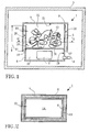
- FIGs. 1 and 2 an inventive device suitable for use in the implementation of the method according to the invention is illustrated diagrammatically.
- the device comprises a first container 1 for accommodating a workpiece 2, which first container 1 is intended for placement in a second container 3 as the workpiece 2 is heated.
- the second container 3 can be any arbitrary oven which is provided with a pump so that a vacuum can be created in the oven during heat-treatment of workpieces 2 in the oven.
- the invention can be applied at different vacuum levels and total pressure in the oven in the order of magnitude of 10 -2 mbar has proved to be appropriate.
- the first container 1 further comprises a first means 4 for introduction of a protective gas and a second means 5 for establishment of an atmospheric connection between the first container 1 and the second container 3.
- a first means 4 for introduction of a protective gas
- a second means 5 for establishment of an atmospheric connection between the first container 1 and the second container 3.
- the first means is a valve 4, with associated connections, disposed in the first container 1 and the second means is a duct 5 connecting the first container 1 to the environment, i.e. to the second container 3 when the first container 1 is placed in the second container 3.
- the first container has at least one such duct, but, in another embodiment, could have two or more ducts.
- the duct 5 can be produced in a variety of ways within the scope of the invention
- the device in the embodiment illustrated in Fig. 1 which has a first container 1 consisting of two parts 6, 7, in the form of a box 6 and a lid 7 for the box, for accommodating the workpiece 2 and, at the same time, creating the duct 5, has the advantage that no special means is required to open and close the first container 1 when a workpiece 2 is to be placed in or taken out of this.
- the lid 7 can quite simply be removed from the box 6, after which access is gained to the interior of the box.
- the lid 7 is disposed in the first container 1 such that the duct 5 is formed between the lid 7 and the box 6.
- the cross section 8 of the duct 5 is therefore, in this case, annular.
- one or more fixed or loose distancing elements (not shown) disposed between the upper edge 9 of the box and the lid 7 can be used to position the lid 7 and the box 6 in relation to each other so that a desired gap is obtained between the lid and the box.
- the duct 5 expediently has a cross section 8 possessing at least one dimension 10, here the gap width 10 between the lid and the box in the horizontal direction, with an extent in the same order of magnitude as the mean free path which the contaminant has in the atmosphere prevailing in the duct 5 as the workpiece 2 is heated, and the duct 5 preferably has a cross section possessing at least one dimension with an extent which is less than the mean free path which the contaminant has in the atmosphere prevailing in the duct 5 as the workpiece 2 is heated.
- the duct 5 has an extent in the longitudinal direction 11 which is many times greater than the extent of at least one cross-sectional dimension 10 of the duct 5 and, preferably, the duct 5 has an extent in the longitudinal direction 11 which is more than 10 times greater than the extent of at least one cross-sectional dimension of the duct 5. In certain cases, an extent of the duct which is 50 times, and preferably 100 times greater than the extent of at least one cross-sectional dimension of the duct is more advantageous. It is desirable if the volume of the duct 5 is relatively large. This means that the duct 5 expediently has a second sizeable cross-sectional dimension and, as described earlier, a large extent in the longitudinal direction.
- a cross-sectional dimension 12 of the duct 5 extends along the whole of the circumference of the first container 1, which means that, despite the relatively small extent of the gap 10 between the box 6 and the lid 7, the duct 5 has a relatively large cross-sectional area 8.
- the volume of the duct 5, i.e. the length of the duct x the cross-sectional area of the duct, in this case the duct length x the gap width x the box circumference, is expediently tailored to the volume of the first container so that the volume relationship V 1 /V k between the volume V 1 of the first container and the volume V k of the duct is less than 20, preferably less than 15 and, more preferably, less than 10.
- chip goods 13 in the form of chips, for example, for providing surfaces for the capture of said contaminant by dint of a reaction between the contaminant and the surfaces of the piece goods 13.
- chips i.e. material separated in the machine-working of a workpiece
- other piece goods which are thread-like or particular in form, such as, for example, a powder or the like, and which have surfaces suitable for capturing a contaminant.
- the device according to the embodiment in Figures 1 and 2 comprises a means 14, for example a dividing plate, for dividing the first container 1 into a first chamber 15 and a second chamber 16.
- the dividing plate 14 is tailored to the shape and size of the first container 1 so that a gap 17 is formed between the outer edge 18 of the dividing plate 14 and the inner limit face 19 of the first container 1.
- Chips 13 with high affinity for one or more contaminants can hence be disposed in the first chamber 15, so that, while the first and the second chamber 15, 16 of the first container 1 are in mutual atmospheric connection, the chips 13 are separated from the workpiece 2 present in the second chamber 16.
- the dividing plate could have flanges, such as plates, which are essentially parallel with the inner limit face of the first container, so that the gap 17 acquires a larger extent in the longitudinal direction (in the vertical direction in Fig. 1 ), which means that a second duct is formed between the flanges and the internal limit face of the first container.
- the second duct which therefore, in this case, connects the first and the second chamber, can be dimensioned so that it acquires essentially identical properties to the abovementioned duct situated between the box and the lid.
- the chips 13 can be made of titanium, for example, and can advantageously be made of the same material as the workpiece 2 to be heat-treated or soldered.
- a material with high affinity for the contaminant can also be utilized in the production and/or preparation of the first container 1.
- the internal face 20 of the duct and/or the inner side 19 of the first container can be lined with such a material in order further to reduce the risk of contamination of the workpiece.
- duct 5 is configured as an elongated, serpentine loop to inhibit the contaminant from reaching the workpiece.
- a long duct 5 can thereby be obtained in a space-saving manner.
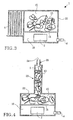
- the latter is provided with a tight-shutting door 22 or lid or the like, so that the container 1 can be opened and closed according to requirement.
- a further variant of the device according to the invention is illustrated diagrammatically, in which the duct 5 is configured as an elongated column.
- the column has a first portion 23, of larger cross-sectional area, disposed next to the first container 1, and which portion contains chips 13 with high affinity for a contaminant, and a second portion 25, of smaller cross-sectional area, disposed next to the environment-facing mouth 24 of the duct 5.
- the outer portion 25 of the duct 5 can have a cross-sectional dimension in the order of magnitude described earlier in this application, whereas the inner portion 23, in certain cases, can be permitted to have larger cross-sectional dimensions which allow chips 13 to be placed in a practical manner in the column.
- the column and a lid 22 which shuts tight against the container can be made integrated in a detachable part to enable the first container 1 to be opened and closed.
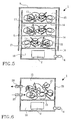
- FIG. 5 a further variant of the device according to the invention is illustrated diagrammatically, in which the first container 1 is provided with a plurality of chambers 15 for the accommodation of chips 13 at different levels in the first container 1.
- a dividing plate 14 is disposed between each set of two mutually adjoining chambers, so that a gap 17 is formed between the outer edge of the dividing plate and the internal limit face of the first container.
- FIG. 6 a further variant of the device according to the invention is illustrated diagrammatically, utilizing valves instead of a duct to establish the necessary connection with the environment, i.e. with the second container when the first container 1 is placed in the second container.
- the first container is provided with three valves 4, 26, 27 in the example illustrated in Fig. 6 , it is possible, at least in certain cases, to utilize a lesser number of valves by making it/them multifunctional.
- the first valve 4 constitutes a means for introducing protective gas into the first container.
- a third valve 27 is designed, during heating of the workpiece, to equalize any pressure differences between the first 1 and second container 3 should a difference in total pressure arise between the first and second container, which difference risks damaging the first container 1.
- a workpiece which is required to be heated for example for the execution of a soldering
- a first container is flushed and filled with a protective gas.
- the duration of the flushing is tailored to the geometric complexity of the workpiece and can range from a few minutes to a number of hours. Flushing of the container with a protective gas, such as, for example, argon, results in partial pressure for the contaminant being lowered.
- the first container filled with protective gas is then placed in a second container, preferably an oven and, in a second step, the partial pressure of the contaminant in the first container is further lowered by the evacuation of the second container, and hence the first container, to create a vacuum inside the first and second container.
- the air is thus pumped out of the oven and the protective gas and remaining contaminants flow out of the first container to the second container and onward out from the second container to the environment.
- Oxygen is an agent which, when workpieces made of certain materials are heated, should as far as possible be minimized in the atmosphere surrounding the workpiece, since the oxygen can otherwise react with the material and form compounds and/or phases which produce undesirable properties of the material.
- Other examples of contaminants are various nitrogen compounds and gaseous carbon compounds.
- V 2 0.5-1 m 3 for the second container
- the invention is not, of course, limited to the volume of the second container, but a relatively small oven is advantageous.
- a larger-volume oven which tends to equalize the oxygen partial pressure inside the first container, will contaminate the first container to a greater extent than a smaller-volume oven.
- a valve system could be used in combination with a duct and these components could interact so that, when the valve is opened at a certain total pressure in the second container, contamination of the workpiece can still be inhibited by the fact that the contaminant, after having passed through the valve, must pass through the duct in order to get into the first container.
Landscapes
- Chemical & Material Sciences (AREA)
- Engineering & Computer Science (AREA)
- Materials Engineering (AREA)
- Thermal Sciences (AREA)
- Crystallography & Structural Chemistry (AREA)
- Mechanical Engineering (AREA)
- Physics & Mathematics (AREA)
- Metallurgy (AREA)
- Organic Chemistry (AREA)
- Furnace Details (AREA)
- Sampling And Sample Adjustment (AREA)
- Electrical Discharge Machining, Electrochemical Machining, And Combined Machining (AREA)
- Glass Compositions (AREA)
- Muffle Furnaces And Rotary Kilns (AREA)
Claims (18)
- Verfahren zum Hemmen der Verunreinigung eines Werkstücks (2) durch eine Verunreinigungssubstanz bei der Erwärmung des Werkstücks, wobei das Verfahren beinhaltet, dass das Werkstück in einem ersten Behälter (1) platziert wird, dadurch gekennzeichnet, dass
bei einem ersten Schritt der erste Behälter (1) gespült und mit einem Schutzgas gefüllt wird, dass der erste Behälter (1) in einem zweiten Behälter (3) platziert wird, wobei eine Verbindungseinrichtung (5) zur Herstellung einer atmosphärischen Verbindung zwischen dem ersten Behälter und dem zweiten Behälter verwendet wird, und dass bei einem zweiten Schritt der zweite Behälter (3), und somit der erste Behälter (1), evakuiert wird, um ein Vakuum innen in dem ersten und zweiten Behälter zu erzeugen, um während des ersten und zweiten Schritts den Partialdruck für die Verunreinigungssubstanz in dem ersten Behälter (1) zu verringern, bevor das Werkstück (2) erwärmt wird. - Verfahren nach Anspruch 1, dadurch gekennzeichnet, dass bei der Erwärmung des Werkstücks (2) der Transport der Verunreinigungssubstanz von dem zweiten Behälter (3) zu dem ersten Behälter (1) dadurch gehemmt wird, dass die Verunreinigungssubstanz durch einen Kanal (5) hindurchgehen muss, um in den ersten Behälter zu gelangen.
- Verfahren nach Anspruch 2, dadurch gekennzeichnet, dass bei der Erwärmung des Werkstücks (2) der Transport der Verunreinigungssubstanz von dem zweiten Behälter (3) zu dem ersten Behälter (1) dadurch gehemmt wird, dass die Verunreinigungssubstanz durch den Kanal (5) hindurchgehen muss, um den ersten Behälter zu erreichen, wobei der Kanal einen Querschnitt hat, der wenigstens eine Abmessung (10) mit einer Ausdehnung in der gleichen Größenordnung wie die mittlere freie Weglänge besitzt, die die Verunreinigungssubstanz in der in dem Kanal (5) vorherrschenden Atmosphäre hat, wenn das Werkstück (2) erwärmt wird.
- Verfahren nach Anspruch 2, dadurch gekennzeichnet, dass bei der Erwärmung des Werkstücks (2) der Transport der Verunreinigungssubstanz von dem zweiten Behälter (3) zu dem ersten Behälter (1) dadurch gehemmt wird, dass die Verunreinigungssubstanz durch den Kanal (5) hindurchgehen muss, um den ersten Behälter (1) zu erreichen, wobei der Kanal einen Querschnitt hat, der wenigstens eine Abmessung (10) mit einer geringeren Ausdehnung als die mittlere freie Weglänge besitzt, die die Verunreinigungssubstanz in der in dem Kanal (5) vorherrschenden Atmosphäre hat, wenn das Werkstück (2) erwärmt wird.
- Verfahren nach den Ansprüchen 2 bis 4, dadurch gekennzeichnet, dass bei der Erwärmung des Werkstücks (2) der Transport der Verunreinigungssubstanz von dem zweiten Behälter (3) zu dem ersten Behälter (1) dadurch gehemmt wird, dass die Verunreinigungssubstanz durch den Kanal (5) hindurchgehen muss, um den ersten Behälter zu erreichen, wobei die Ausdehnung des Kanals in Längsrichtung (11) um ein Vielfaches größer als die Ausdehnung von mindestens einer Querschnittsabmessung (10) des Kanals (5) ist.
- Verfahren nach Anspruch 5, dadurch gekennzeichnet, dass die Verunreinigungssubstanz durch den Kanal (5) hindurchgehen muss, um den ersten Behälter (1) zu erreichen, wobei die Ausdehnung des Kanals in Längsrichtung (11) mehr als 10-mal so groß wie die Ausdehnung von wenigstens einer Querschnittsabmessung (10) des Kanals (5) ist.
- Verfahren nach Anspruch 5, dadurch gekennzeichnet, dass die Verunreinigungssubstanz durch den Kanal (5) hindurchgehen muss, um den ersten Behälter (1) zu erreichen, wobei die Ausdehnung des Kanals in Längsrichtung (11) mehr als 50-mal so groß wie die Ausdehnung von wenigstens einer Querschnittsabmessung (10) des Kanals (5) ist.
- Verfahren nach Anspruch 5, dadurch gekennzeichnet, dass die Verunreinigungssubstanz durch den Kanal (5) hindurchgehen muss, um den ersten Behälter (1) zu erreichen, wobei die Ausdehnung des Kanals in Längsrichtung (11) mehr als 100-mal so groß wie die Ausdehnung von wenigstens einer Querschnittsabmessung (10) des Kanals (5) ist.
- Verfahren nach einem der Ansprüche 2 bis 8, dadurch gekennzeichnet, dass bei der Erwärmung des Werkstücks (2) der Transport der Verunreinigungssubstanz von dem zweiten Behälter (3) zu dem ersten Behälter (1) dadurch gehemmt wird, dass die Verunreinigungssubstanz durch den Kanal (5) hindurchgehen muss, um den ersten Behälter zu erreichen, wobei das Volumen des Kanals auf das Volumen des ersten Behälters so zugeschnitten ist, dass das Volumenverhältnis (V1/Vk) zwischen dem Volumen (V1) des ersten Behälters und dem Volumen (Vk) des Kanals weniger als 20 beträgt.
- Verfahren nach einem der Ansprüche 2 bis 8, dadurch gekennzeichnet, dass bei der Erwärmung des Werkstücks der Transport der Verunreinigungssubstanz von dem zweiten Behälter (3) zu dem ersten Behälter (1) dadurch gehemmt wird, dass die Verunreinigungssubstanz durch den Kanal (5) hindurchgehen muss, um den ersten Behälter zu erreichen, wobei das Volumen des Kanals auf das Volumen des ersten Behälters so zugeschnitten ist, dass das Volumenverhältnis (V1/Vk) zwischen dem Volumen (V1) des ersten Behälters und dem Volumen (Vk) des Kanals weniger als 15 beträgt.
- Verfahren nach einem der Ansprüche 2 bis 8, dadurch gekennzeichnet, dass bei der Erwärmung des Werkstücks (2) der Transport der Verunreinigungssubstanz von dem zweiten Behälter (3) zu dem ersten Behälter (1) dadurch gehemmt wird, dass die Verunreinigungssubstanz durch den Kanal (5) hindurchgehen muss, um den ersten Behälter zu erreichen, wobei das Volumen des Kanals auf das Volumen des ersten Behälters so zugeschnitten ist, dass das Volumenverhältnis (V1/Nk) zwischen dem Volumen (V1) des ersten Behälters und dem Volumen (Vk) des Kanals weniger als 10 beträgt.
- Verfahren nach Anspruch 1, dadurch gekennzeichnet, dass bei der Evakuierung des ersten und des zweiten Behälters (1, 3) ein Ventil (26) des ersten Behälters (1) geöffnet wird, um eine atmosphärische Verbindung zwischen dem ersten Behälter und dem zweiten Behälters herzustellen, wobei das Ventil (26) nach vollendeter Evakuierung geschlossen wird.
- Verfahren nach Anspruch 1 oder 12, dadurch gekennzeichnet, dass bei der Erwärmung des Werkstücks (2) ein Ventil (27) des ersten Behälters (1) bei einem einen vorher bestimmten Wert überschreitenden Gesamtdruck in dem zweiten Behälter (3) oder bei einem einen vorher bestimmten Wert überschreitenden Druckunterschied zwischen dem ersten und zweiten Behälter geöffnet wird, um die Komprimierung des ersten Behälters (1) zu hemmen.
- Verfahren nach einem der vorhergehenden Ansprüche, dadurch gekennzeichnet, dass der erste Behälter (1) mit dem Schutzgas gefüllt wird, bevor er in dem zweiten Behälter (3) platziert wird.
- Verfahren nach einem der vorhergehenden Ansprüche, dadurch gekennzeichnet, dass Stückware (13) in dem ersten Behälter (1) platziert wird, um Oberflächen für das Einfangen der Verunreinigungssubstanz mittels einer Reaktion zwischen der Verunreinigungssubstanz und den Oberflächen der Stückware (13) bereitzustellen.
- Verfahren nach Anspruch 15, dadurch gekennzeichnet, dass derartige Stückware (13) in einer ersten Kammer (15) des ersten Behälters (1) so platziert wird, dass diese Stückware (13) von dem in einer zweiten Kammer (16) des ersten Behälters vorhandenen Werkstück (2) getrennt ist, wobei die erste Kammer (15) und die zweite Kammer (16) des ersten Behälters in gegenseitiger atmosphärischer Verbindung stehen.
- Verfahren nach einem der Ansprüche 2 bis 11 oder 15 bis 16, dadurch gekennzeichnet, dass Stückware (13) in dem Kanal (5) platziert wird, um Oberflächen für das Einfangen der Verunreinigungssubstanz mittels einer Reaktion zwischen der Verunreinigungssubstanz und den Oberflächen der Stückware (13) zu schaffen.
- Verfahren nach einem der vorhergehenden Ansprüche, dadurch gekennzeichnet, dass das Werkstück (2) zum Löten des Werkstücks erwärmt wird.
Applications Claiming Priority (3)
| Application Number | Priority Date | Filing Date | Title |
|---|---|---|---|
| US46465303P | 2003-04-23 | 2003-04-23 | |
| SE0301192A SE526447C2 (sv) | 2003-04-23 | 2003-04-23 | Förfarande och anordning för att motverka kontamination hos ett arbetsstycke |
| PCT/SE2004/000624 WO2004094057A1 (en) | 2003-04-23 | 2004-04-22 | Method and device for inhibiting contamination of a workpiece |
Publications (2)
| Publication Number | Publication Date |
|---|---|
| EP1620197A1 EP1620197A1 (de) | 2006-02-01 |
| EP1620197B1 true EP1620197B1 (de) | 2009-07-01 |
Family
ID=33312715
Family Applications (1)
| Application Number | Title | Priority Date | Filing Date |
|---|---|---|---|
| EP04728999A Expired - Lifetime EP1620197B1 (de) | 2003-04-23 | 2004-04-22 | Verfahren zur verhinderung der verunreinigung eines werkstücks |
Country Status (5)
| Country | Link |
|---|---|
| EP (1) | EP1620197B1 (de) |
| AT (1) | ATE435065T1 (de) |
| DE (1) | DE602004021794D1 (de) |
| RU (1) | RU2358018C2 (de) |
| WO (1) | WO2004094057A1 (de) |
Families Citing this family (2)
| Publication number | Priority date | Publication date | Assignee | Title |
|---|---|---|---|---|
| CN102922072A (zh) * | 2012-10-30 | 2013-02-13 | 西安航空动力股份有限公司 | 一种采用铜锰钴镍钎料的真空钎焊方法 |
| RU2535818C1 (ru) * | 2013-07-30 | 2014-12-20 | Закрытое акционерное общество "Сатурн-инструментальный завод" | Способ защиты поверхности деталей при нагреве в печах |
Family Cites Families (8)
| Publication number | Priority date | Publication date | Assignee | Title |
|---|---|---|---|---|
| US3700435A (en) * | 1971-03-01 | 1972-10-24 | Crucible Inc | Method for making powder metallurgy shapes |
| SE361424B (de) * | 1971-11-26 | 1973-11-05 | Hoeganaes Ab | |
| DE2448714A1 (de) * | 1974-10-12 | 1976-04-22 | Robert Arnold Gray | Verfahren zur behandlung von gegenstaenden unter vakuum mit gaszufuhr |
| US4175921A (en) * | 1976-12-13 | 1979-11-27 | Allegheny Ludlum Industries, Inc. | Apparatus for removing gases from particles |
| GB2052030B (en) * | 1980-04-28 | 1984-02-08 | Gen Electric | Construction of special atmosphere furnace |
| JPS61107091A (ja) * | 1984-10-26 | 1986-05-24 | インタ−ナショナル ビジネス マシ−ンズ コ−ポレ−ション | 加工材料容器 |
| RU2083687C1 (ru) * | 1994-10-11 | 1997-07-10 | Казанский государственный технический университет им.А.Н.Туполева | Вакуумная установка для термической обработки изделий |
| RU2061764C1 (ru) * | 1994-10-11 | 1996-06-10 | Казанский государственный технический университет им.А.Н.Туполева | Вакуумная установка для термической обработки изделий |
-
2004
- 2004-04-22 AT AT04728999T patent/ATE435065T1/de not_active IP Right Cessation
- 2004-04-22 RU RU2005135971/02A patent/RU2358018C2/ru not_active IP Right Cessation
- 2004-04-22 DE DE602004021794T patent/DE602004021794D1/de not_active Expired - Lifetime
- 2004-04-22 WO PCT/SE2004/000624 patent/WO2004094057A1/en not_active Ceased
- 2004-04-22 EP EP04728999A patent/EP1620197B1/de not_active Expired - Lifetime
Also Published As
| Publication number | Publication date |
|---|---|
| EP1620197A1 (de) | 2006-02-01 |
| DE602004021794D1 (de) | 2009-08-13 |
| RU2005135971A (ru) | 2007-05-27 |
| RU2358018C2 (ru) | 2009-06-10 |
| WO2004094057A1 (en) | 2004-11-04 |
| ATE435065T1 (de) | 2009-07-15 |
Similar Documents
| Publication | Publication Date | Title |
|---|---|---|
| US5533736A (en) | Thermal processing apparatus | |
| JPH04269822A (ja) | 熱処理装置の封止構造 | |
| JP2009115413A (ja) | 熱処理装置 | |
| EP1620197B1 (de) | Verfahren zur verhinderung der verunreinigung eines werkstücks | |
| US5253796A (en) | Retort for gas diffusion bonding of metals under vacuum | |
| US6491518B1 (en) | Apparatus for high-temperature and high-pressure treatment | |
| US7410547B2 (en) | Method and device for inhibiting contamination of a workpiece | |
| JP3853487B2 (ja) | 連続式熱処理炉 | |
| US6767504B2 (en) | Heat treatment furnace | |
| JP4864696B2 (ja) | 工作物の汚染を抑える方法および装置 | |
| US9242313B2 (en) | Welding furnace and viewport assembly | |
| US10436512B1 (en) | Base component for a thermoprocessing system, a thermoprocessing system, and a thermoprocessing method | |
| JP2009185349A (ja) | 多室型熱処理炉 | |
| US9951405B2 (en) | Localized heat treating of net shape titanium parts | |
| US20030201584A1 (en) | Annealing apparatus | |
| US4701127A (en) | Controlled atmosphere capsule for fluxless brazing | |
| AU2001294383A1 (en) | Gas-tight or partly gas-permeable transport package, and method and apparatus for manufacturing same | |
| JPH02159372A (ja) | スパッタリングターゲット用保護容器 | |
| JPH01169174A (ja) | 真空炉の蓋の固定方法 | |
| JPS634957Y2 (de) | ||
| KR102508666B1 (ko) | 타이타늄 탈산 시스템 및 이를 이용한 타이타늄 탈산 방법 | |
| JP2923534B2 (ja) | コイル状被処理材の焼鈍方法及び熱処理炉 | |
| RU2186860C2 (ru) | Способ термической обработки деталей из металлов, сталей и сплавов | |
| JPH03207810A (ja) | 複数チャンバ真空装置 | |
| JPH06151340A (ja) | 熱処理装置 |
Legal Events
| Date | Code | Title | Description |
|---|---|---|---|
| PUAI | Public reference made under article 153(3) epc to a published international application that has entered the european phase |
Free format text: ORIGINAL CODE: 0009012 |
|
| 17P | Request for examination filed |
Effective date: 20051123 |
|
| AK | Designated contracting states |
Kind code of ref document: A1 Designated state(s): AT BE BG CH CY CZ DE DK EE ES FI FR GB GR HU IE IT LI LU MC NL PL PT RO SE SI SK TR |
|
| DAX | Request for extension of the european patent (deleted) | ||
| 17Q | First examination report despatched |
Effective date: 20080207 |
|
| RTI1 | Title (correction) |
Free format text: METHOD FOR INHIBITING CONTAMINATION OF A WORKPIECE |
|
| GRAP | Despatch of communication of intention to grant a patent |
Free format text: ORIGINAL CODE: EPIDOSNIGR1 |
|
| GRAS | Grant fee paid |
Free format text: ORIGINAL CODE: EPIDOSNIGR3 |
|
| GRAA | (expected) grant |
Free format text: ORIGINAL CODE: 0009210 |
|
| AK | Designated contracting states |
Kind code of ref document: B1 Designated state(s): AT BE BG CH CY CZ DE DK EE ES FI FR GB GR HU IE IT LI LU MC NL PL PT RO SE SI SK TR |
|
| REG | Reference to a national code |
Ref country code: GB Ref legal event code: FG4D |
|
| REG | Reference to a national code |
Ref country code: CH Ref legal event code: EP |
|
| REG | Reference to a national code |
Ref country code: IE Ref legal event code: FG4D |
|
| REF | Corresponds to: |
Ref document number: 602004021794 Country of ref document: DE Date of ref document: 20090813 Kind code of ref document: P |
|
| PG25 | Lapsed in a contracting state [announced via postgrant information from national office to epo] |
Ref country code: SI Free format text: LAPSE BECAUSE OF FAILURE TO SUBMIT A TRANSLATION OF THE DESCRIPTION OR TO PAY THE FEE WITHIN THE PRESCRIBED TIME-LIMIT Effective date: 20090701 |
|
| NLV1 | Nl: lapsed or annulled due to failure to fulfill the requirements of art. 29p and 29m of the patents act | ||
| PG25 | Lapsed in a contracting state [announced via postgrant information from national office to epo] |
Ref country code: ES Free format text: LAPSE BECAUSE OF FAILURE TO SUBMIT A TRANSLATION OF THE DESCRIPTION OR TO PAY THE FEE WITHIN THE PRESCRIBED TIME-LIMIT Effective date: 20091012 Ref country code: EE Free format text: LAPSE BECAUSE OF FAILURE TO SUBMIT A TRANSLATION OF THE DESCRIPTION OR TO PAY THE FEE WITHIN THE PRESCRIBED TIME-LIMIT Effective date: 20090701 Ref country code: SE Free format text: LAPSE BECAUSE OF FAILURE TO SUBMIT A TRANSLATION OF THE DESCRIPTION OR TO PAY THE FEE WITHIN THE PRESCRIBED TIME-LIMIT Effective date: 20090701 Ref country code: AT Free format text: LAPSE BECAUSE OF FAILURE TO SUBMIT A TRANSLATION OF THE DESCRIPTION OR TO PAY THE FEE WITHIN THE PRESCRIBED TIME-LIMIT Effective date: 20090701 Ref country code: FI Free format text: LAPSE BECAUSE OF FAILURE TO SUBMIT A TRANSLATION OF THE DESCRIPTION OR TO PAY THE FEE WITHIN THE PRESCRIBED TIME-LIMIT Effective date: 20090701 |
|
| PG25 | Lapsed in a contracting state [announced via postgrant information from national office to epo] |
Ref country code: NL Free format text: LAPSE BECAUSE OF FAILURE TO SUBMIT A TRANSLATION OF THE DESCRIPTION OR TO PAY THE FEE WITHIN THE PRESCRIBED TIME-LIMIT Effective date: 20090701 Ref country code: PL Free format text: LAPSE BECAUSE OF FAILURE TO SUBMIT A TRANSLATION OF THE DESCRIPTION OR TO PAY THE FEE WITHIN THE PRESCRIBED TIME-LIMIT Effective date: 20090701 |
|
| PG25 | Lapsed in a contracting state [announced via postgrant information from national office to epo] |
Ref country code: BG Free format text: LAPSE BECAUSE OF FAILURE TO SUBMIT A TRANSLATION OF THE DESCRIPTION OR TO PAY THE FEE WITHIN THE PRESCRIBED TIME-LIMIT Effective date: 20091001 Ref country code: PT Free format text: LAPSE BECAUSE OF FAILURE TO SUBMIT A TRANSLATION OF THE DESCRIPTION OR TO PAY THE FEE WITHIN THE PRESCRIBED TIME-LIMIT Effective date: 20091102 |
|
| PG25 | Lapsed in a contracting state [announced via postgrant information from national office to epo] |
Ref country code: RO Free format text: LAPSE BECAUSE OF FAILURE TO SUBMIT A TRANSLATION OF THE DESCRIPTION OR TO PAY THE FEE WITHIN THE PRESCRIBED TIME-LIMIT Effective date: 20090701 Ref country code: DK Free format text: LAPSE BECAUSE OF FAILURE TO SUBMIT A TRANSLATION OF THE DESCRIPTION OR TO PAY THE FEE WITHIN THE PRESCRIBED TIME-LIMIT Effective date: 20090701 Ref country code: CZ Free format text: LAPSE BECAUSE OF FAILURE TO SUBMIT A TRANSLATION OF THE DESCRIPTION OR TO PAY THE FEE WITHIN THE PRESCRIBED TIME-LIMIT Effective date: 20090701 |
|
| PLBE | No opposition filed within time limit |
Free format text: ORIGINAL CODE: 0009261 |
|
| STAA | Information on the status of an ep patent application or granted ep patent |
Free format text: STATUS: NO OPPOSITION FILED WITHIN TIME LIMIT |
|
| PG25 | Lapsed in a contracting state [announced via postgrant information from national office to epo] |
Ref country code: SK Free format text: LAPSE BECAUSE OF FAILURE TO SUBMIT A TRANSLATION OF THE DESCRIPTION OR TO PAY THE FEE WITHIN THE PRESCRIBED TIME-LIMIT Effective date: 20090701 Ref country code: BE Free format text: LAPSE BECAUSE OF FAILURE TO SUBMIT A TRANSLATION OF THE DESCRIPTION OR TO PAY THE FEE WITHIN THE PRESCRIBED TIME-LIMIT Effective date: 20090701 |
|
| 26N | No opposition filed |
Effective date: 20100406 |
|
| PG25 | Lapsed in a contracting state [announced via postgrant information from national office to epo] |
Ref country code: GR Free format text: LAPSE BECAUSE OF FAILURE TO SUBMIT A TRANSLATION OF THE DESCRIPTION OR TO PAY THE FEE WITHIN THE PRESCRIBED TIME-LIMIT Effective date: 20091002 |
|
| PG25 | Lapsed in a contracting state [announced via postgrant information from national office to epo] |
Ref country code: MC Free format text: LAPSE BECAUSE OF NON-PAYMENT OF DUE FEES Effective date: 20100430 |
|
| REG | Reference to a national code |
Ref country code: CH Ref legal event code: PL |
|
| PG25 | Lapsed in a contracting state [announced via postgrant information from national office to epo] |
Ref country code: IE Free format text: LAPSE BECAUSE OF NON-PAYMENT OF DUE FEES Effective date: 20100422 |
|
| PG25 | Lapsed in a contracting state [announced via postgrant information from national office to epo] |
Ref country code: LI Free format text: LAPSE BECAUSE OF NON-PAYMENT OF DUE FEES Effective date: 20100430 Ref country code: CH Free format text: LAPSE BECAUSE OF NON-PAYMENT OF DUE FEES Effective date: 20100430 |
|
| PG25 | Lapsed in a contracting state [announced via postgrant information from national office to epo] |
Ref country code: IT Free format text: LAPSE BECAUSE OF FAILURE TO SUBMIT A TRANSLATION OF THE DESCRIPTION OR TO PAY THE FEE WITHIN THE PRESCRIBED TIME-LIMIT Effective date: 20090701 |
|
| PGFP | Annual fee paid to national office [announced via postgrant information from national office to epo] |
Ref country code: DE Payment date: 20120425 Year of fee payment: 9 |
|
| PG25 | Lapsed in a contracting state [announced via postgrant information from national office to epo] |
Ref country code: CY Free format text: LAPSE BECAUSE OF FAILURE TO SUBMIT A TRANSLATION OF THE DESCRIPTION OR TO PAY THE FEE WITHIN THE PRESCRIBED TIME-LIMIT Effective date: 20090701 |
|
| PGFP | Annual fee paid to national office [announced via postgrant information from national office to epo] |
Ref country code: GB Payment date: 20120418 Year of fee payment: 9 Ref country code: FR Payment date: 20120504 Year of fee payment: 9 |
|
| PG25 | Lapsed in a contracting state [announced via postgrant information from national office to epo] |
Ref country code: HU Free format text: LAPSE BECAUSE OF FAILURE TO SUBMIT A TRANSLATION OF THE DESCRIPTION OR TO PAY THE FEE WITHIN THE PRESCRIBED TIME-LIMIT Effective date: 20100102 Ref country code: LU Free format text: LAPSE BECAUSE OF NON-PAYMENT OF DUE FEES Effective date: 20100422 |
|
| PG25 | Lapsed in a contracting state [announced via postgrant information from national office to epo] |
Ref country code: TR Free format text: LAPSE BECAUSE OF FAILURE TO SUBMIT A TRANSLATION OF THE DESCRIPTION OR TO PAY THE FEE WITHIN THE PRESCRIBED TIME-LIMIT Effective date: 20090701 |
|
| GBPC | Gb: european patent ceased through non-payment of renewal fee |
Effective date: 20130422 |
|
| PG25 | Lapsed in a contracting state [announced via postgrant information from national office to epo] |
Ref country code: DE Free format text: LAPSE BECAUSE OF NON-PAYMENT OF DUE FEES Effective date: 20131101 Ref country code: GB Free format text: LAPSE BECAUSE OF NON-PAYMENT OF DUE FEES Effective date: 20130422 |
|
| REG | Reference to a national code |
Ref country code: FR Ref legal event code: ST Effective date: 20131231 |
|
| REG | Reference to a national code |
Ref country code: DE Ref legal event code: R119 Ref document number: 602004021794 Country of ref document: DE Effective date: 20131101 |
|
| PG25 | Lapsed in a contracting state [announced via postgrant information from national office to epo] |
Ref country code: FR Free format text: LAPSE BECAUSE OF NON-PAYMENT OF DUE FEES Effective date: 20130430 |