EP1620592B1 - Machine a coudre - Google Patents
Machine a coudre Download PDFInfo
- Publication number
- EP1620592B1 EP1620592B1 EP04730816A EP04730816A EP1620592B1 EP 1620592 B1 EP1620592 B1 EP 1620592B1 EP 04730816 A EP04730816 A EP 04730816A EP 04730816 A EP04730816 A EP 04730816A EP 1620592 B1 EP1620592 B1 EP 1620592B1
- Authority
- EP
- European Patent Office
- Prior art keywords
- piercer
- needle
- sewing machine
- needles
- axis
- Prior art date
- Legal status (The legal status is an assumption and is not a legal conclusion. Google has not performed a legal analysis and makes no representation as to the accuracy of the status listed.)
- Expired - Lifetime
Links
- 238000009958 sewing Methods 0.000 title claims abstract description 62
- 239000000463 material Substances 0.000 claims description 19
- 230000001154 acute effect Effects 0.000 claims description 9
- 230000015572 biosynthetic process Effects 0.000 claims description 6
- 230000032258 transport Effects 0.000 claims 6
- 239000004744 fabric Substances 0.000 description 31
- 238000009941 weaving Methods 0.000 description 10
- 238000000034 method Methods 0.000 description 4
- 206010003402 Arthropod sting Diseases 0.000 description 3
- 238000005452 bending Methods 0.000 description 3
- 238000004519 manufacturing process Methods 0.000 description 3
- 230000035515 penetration Effects 0.000 description 3
- 238000006073 displacement reaction Methods 0.000 description 2
- 230000000149 penetrating effect Effects 0.000 description 2
- 230000001419 dependent effect Effects 0.000 description 1
- 210000005069 ears Anatomy 0.000 description 1
- 230000000694 effects Effects 0.000 description 1
- 238000005516 engineering process Methods 0.000 description 1
- 238000003780 insertion Methods 0.000 description 1
- 230000037431 insertion Effects 0.000 description 1
- 230000003287 optical effect Effects 0.000 description 1
- 230000001360 synchronised effect Effects 0.000 description 1
- 239000002759 woven fabric Substances 0.000 description 1
Images


Classifications
-
- D—TEXTILES; PAPER
- D05—SEWING; EMBROIDERING; TUFTING
- D05C—EMBROIDERING; TUFTING
- D05C7/00—Special-purpose or automatic embroidering machines
- D05C7/04—Special-purpose or automatic embroidering machines for boring or jogging
-
- D—TEXTILES; PAPER
- D05—SEWING; EMBROIDERING; TUFTING
- D05B—SEWING
- D05B37/00—Devices incorporated in sewing machines for slitting, grooving, or cutting
- D05B37/02—Slitting or grooving devices
Definitions
- the invention relates to a sewing machine according to the preamble of claim 1 and a engraver for a sewing machine.
- Hemstitch sewing machines and two-needle sewing machines have been known for around a hundred years and still work on the same principle today. This is that by two needles, each associated with a gripper, two parallel juxtaposed zig-zag seam sections are generated. In order to separate the two seams from each other, the weaving threads are slightly pushed apart and a recess or a hole is formed in the sewing material with a leader. To be able to wrap around the spaced-apart woven threads at the edges of the holes with the needles, deep axial grooves are recessed in the engraver laterally. Due to the tension of the weaving threads, when the stitcher is pierced in the sewing material, a free passage for the needles remains in the grooves.
- the latter are pivotably mounted at the lower end of the common needle needle oscillating perpendicular to the needle plate. and pre-piercing bar attached and swinging. That is, a first pass is made with inwardly pivoted needles, so that their tips in the lateral grooves of the engraver led by the created in the free space of the grooves opening in the fabric down to the grippers. During piercing, the needles are so strongly applied to the grooves that they have a bend. The subsequent stitch is then carried out with swung back, that is substantially vertically penetrating into the fabric then not bent needles. In the subsequent stitch, the needles are pivoted back inwards and are bent when penetrating into the fabric and abut the grooves of the engraver. They are also bent by the grippers something aside, so that the hook tip can detect the upper thread loop.
- a device for producing hollow effects on embroidery machines in which a hole in the embroidery material is initially produced with a drill and, after the drill has been withdrawn from the embroidery material at high speed, a needle at an acute angle to the drill axis for stitch formation in the prefabricated Hole is introduced.
- Such a device can only work reliably if the embroidery material has a suitable structure and the hole produced by the drill does not close when the drill is withdrawn.
- the hole cross section can not be maintained constant.
- German patent specification DE-100 814 relates to a stub device, with which the impressions of the hollow embroidery is prevented.
- stubbing is not the edge of the hole, created by a drill hole by a sewing needle, which interacts with a gripper, bordered. Only the hole that has already been enclosed will be widened again. It is a completely different device.
- Object of the present invention is to provide a sewing machine and a engraver, which overcomes the disadvantages of the known and allows the proper production of hollow seams both loosely as well as tightly woven fabric.
- the farther apart grippers allow the use of a piercer and a piercer with much less conicity, ie with much longer tip, so that the weaving threads are pushed apart less quickly during piercing and thereby yarn breaks can be prevented. Since the two needles lying in a V-shape penetrate the piercer within the opening formed in the sewing material by the piercer, it is avoided that individual weaving threads are not looped around by the sewing threads. The always oscillating in the direction of the needle axis needles are not subject to bending forces and therefore a needle breakage can be excluded by material fatigue. In the further are the ears of the Needles perfectly accessible for the insertion of the needle thread.
- the engraver according to the invention can be fastened to a household sewing machine and makes it possible to produce hollow seams even in the private sector.
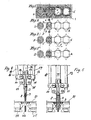
- FIGS. 1 to 5 For a better understanding of the invention and the differences from the prior art are in the FIGS. 1 to 5 the formation of a hemstitch with a conventional hemstitch sewing machine according US-A 2,093,558 illustrated and explained.
- FIG. 1 is the fabric 1 can be seen in the already two hemstitch openings or holes A have been generated.
- the Vorstecher whose cross-section may be, for example, oval, has penetrated into the fabric 1.
- the engraver C located behind at a distance has also penetrated the sewing material 1.
- In the engraver C are laterally two axially extending grooves 3 can be seen (see in particular FIG. 2 ), in which in FIG. 1 already the two needles 8 and 9 are. Due to the spreading movement of the weaving threads through the penetration of a piercer twice, first of the piercer D and then of the piercer C, the weaving threads are pushed to the side and the needles 8 and 9 can penetrate into the recess A.
- FIG. 2 shows the needles 8 and 9 pivoted outwards, swinging outwards in the sewing language, and pierce outside the recess A directly into the fabric 1 a.
- the two upper threads 6 and 7 devoured with the lower threads, not shown, and when pulling out the needles 8.9 from the fabric 1, the stitches are contracted according to the set thread tension and form along the recess A forming zig -Zack seams.
- FIG. 3 shows the third puncture, in which the two needles 8 and 9 are again guided in the grooves formed by the grooves 3 of the engraver C.
- FIG. 1 ' represents the beginning of the production of a new recess A after the fabric 1 has been transported with the conveyor by one step in the direction of the arrow 5.
- the swinging of the two needles 8 and 9 is in the FIGS. 4 and 5 shown closer.
- the two needles 8 and 9 are pivotally connected to two-armed levers 10 and 11 about pivot axes 12,13.
- the two needles 8 and 9 are attached to the first lever arms 14 and 15; the second lever arms 16 and 17 are connected to drive rods 18 and 19.
- the two two-armed levers 10 and 11 are articulated at the front end of a vertically up and down movable Stecherstange 20.
- the two Needles 8,9 are on the Stecherstange 20 and the two engravers C, D, namely the Vorstecher D and the engraver C, attached.
- the engraver C, D and the two needles 8,9 are consequently moved up and down together with the piercing rod 20 perpendicular to the throat plate 21.
- the oblique needles 8,9 experience a bending towards the engraver ..
- FIG. 4 is the Stecherstange 20 with the needles 8 and 9 and the punches D and C in the highest position in which the fabric 1 can be pushed under the needles 8 and 9 and Stecher D and C, respectively.
- the two needles 8 and 9 are steady, ie their tips are close to each other and they are also (in FIG. 4 not visible) according to FIG. 1 in the lateral grooves 3 of the second engraver C.
- ie inclined needles 8 and 9 these are guided together with the punches D and C of the needle bar 20 through the fabric 1 and the needle plate 21 down.
- the two needles 8 and 9 perform a translational motion, ie their tips penetrate close to each other lying in the fabric and the further down driving (not shown) displace the two needles because of their oblique position the fabric 1 to the outside. Shortly before the Hubumledge the Stecherstange 20, the two upper thread loops of the Gripper tips of the two grippers 24 and 25 detected and engulfed with the lower thread.
- FIG. 17 shows, it can be seen that the needle axes V 1 and V 2 are at a preferably acute angle alpha to the axis of movement Y of the piercing rod 20.
- the engraver rod axis Y is perpendicular to the surface of the throat plate 21.
- the movement drive for the two needles 8.9 takes place in the two needle axes V 1 and V 2 with an independent from the drive of the engraver rod 20 but synchronous drive 22nd
- Each of these slots 27 is traversed by one of the two needles 8.9, after the engraver C has penetrated into the fabric 1 and the recess A formed and the weaving threads of the fabric 1 has gently pushed apart.
- a single recess may be provided for both needles 8,9.
- the engraver C can be formed on this oblique grooves 28 which form the passage for the needles 8.9 within the Stecherqueritess (see. Figures 15/16 ).
- the two V-shaped oscillating needles 8,9 are at an angle of preferably 60 ° to each other.
- This entangled position causes with fully inserted needles 8.9 whose tips with that in the corresponding eye 30th Guided upper threads 6,7 are not as close to each other as in the prior art, but in much greater distance.
- This gripper arrangement makes it possible further to form the engraver C much longer and thereby significantly reduce the taper of its tip 30 and thus make the spreading of the weaving threads during piercing gentler because slower and thus to prevent yarn breakage.
- the vertically encircling grippers 24, 25 allow the bobbins accommodated therein to be exchanged without lifting the material 1 from the throat plate 21. Further, such vertical grippers 24,25 seen in sewing direction 5 can be arranged behind the needles 8,9 and thus sewing technique a better stitch pattern can be obtained.
- the two preferably designed as a rotary gripper gripper 24,25 may be driven synchronously or in opposite directions.
- FIG. 11 is the point of intersection K 1 of the two needles 8,9 on the sewing material 1 on the throat plate 21.
- the tips of the needle meet 8.9 in a lateral distance x to the engraver C on the fabric 1 and penetrate this at an angle alpha. So they form the outer punctures of the formed around the hole A zig-zag seam.
- the needle axes V 1 , V 2 as in FIGS. 10 and 12 2 , the point of intersection K 2 of the needles 8, 9 shifts downward, specifically into the plane of the throat plate 21 or of the sewing material 1, which lies on the throat plate 21 (in FIGS FIGS. 9 and 10 Sewing material 1 not shown).
- the recesses A would not synchronously provided on both sides with zig-zag seams, but each offset by a recess A (see. FIG. 7 ). This also means that a hemstitch seam can be produced with only one needle if only one side of the recesses A formed is to be provided with stitches.
- a twin conveyor 31 instead of a conventional conveyor 23, which performs a translatory movement in the throat plate 21, a twin conveyor 31 according to FIG. 8 , This comprises two easily over the surface 32 of the needle plate 21 projecting or guided over this conveyor belts 33. Between the two conveyor belts 33 which are gradually driven and have a freewheel, are preferably two clamping and transport rollers 34,35. These are synchronously drivable and provided with a freewheel. is located above the one transport roller 34, attached to the presser foot, which has been omitted for the sake of clarity in the drawings, a second roller with which the fabric 1 can be kept clamped.
- the fabric is held not only the side of the needle hole 36, but also in front of and behind this as in an embroidery hoop.
- the fabric can therefore neither during stitch formation, glide uncontrolled during the feed.
- the drive of the two conveyor belts 33 and at least one of the two transport rollers 34,35 is usually carried out at every third puncture, ie after completion of a Hohlsaumausnaturalung A.
- the feed corresponds to the distance of the two axes of the engraver C, D and is about 4mm. Such a large hole spacing can not be produced with the known machines.
- FIGS. 13, 14 and FIG. 18 shows how the inventive production of a hemstitch with a piercer C, in which a passage opening 27 for the at least one needle 8 is present, can also be used on a household sewing machine N2.
- the needle 8 is fixed and pierces vertically into the fabric, the at least one engraver C is arranged at an acute angle to the needle axis V 1 . Since in a household sewing machine no drive device for a engraver C is provided and also in the area laterally the needle bar is not enough space for such a drive is present invention the engraver drive housed in a separate, attachable to the sewing machine N2 housing 51.
- the housing 51 is suitably releasably attached to the lower, rear or front side of the upper arm 53 of the sewing machine.
- a drive element such as a linear motor, a crank mechanism or the like, arranged with which the engraver C at an acute angle to the axis V 1 of the needle 8 in the fabric pierceable and retractable.
- three pinholes are made per puncture of the engraver C. This means that the engraver only needs to penetrate the needle into the material at every second puncture of the needle 8 and then has to be pulled out of it again.
- a controller can be accommodated in addition to the linear drive, which, connected to the sewing machine via a cable not visible in the figures or a plug controls the movement of the engraver C.
- a somewhat larger recess 18 must be provided in a needle sewing machine in the throat plate so that the engraver C can penetrate the needle plate 21 before piercing the needle.
- FIG. 13 the engraver C has already penetrated the throat plate 21 and also the needle 8 is driven vertically from above through the recess 27 in the engraver.
- FIG. 14 shows the engraver C and the needle 8 in optimally retracted position, for example, before the fabric is pushed under the needle 8 and the engraver C or when the fabric is advanced by the feed dog.
Landscapes
- Engineering & Computer Science (AREA)
- Textile Engineering (AREA)
- Sewing Machines And Sewing (AREA)
- Inorganic Insulating Materials (AREA)
- Massaging Devices (AREA)
Claims (9)
- Machine à coudre, comprenant au moins une aiguille (8) pour fabriquer un ourlet à jour dans une pièce d'étoffe (1) ainsi qu'un transporteur (31) pour le transport de la pièce d'étoffe, dans laquelle l'axe (V1) de la au moins une aiguille (8) s'étend sous un angle aigu (alpha) par rapport à l'axe (Y) d'un piqueur (C) et dans laquelle il est possible d'entraîner l'aiguille (8) par un entraînement de barre à aiguille et le piqueur (C) par un entraînement de barre à piqueur en direction de l'axe (y) du piqueur (C), caractérisée en ce que le au moins un piqueur (C) est agencé à côté de l'aiguille (8) en regardant dans le sens de couture (5) et comporte une fente (27) qui s'étend dans le piqueur (C) ou au moins une rainure (28) ménagée en périphérie sur le piqueur (C), à travers laquelle la au moins une aiguille (8) peut être passée dans la section transversale du piqueur pendant la formation du piquage alors que le piqueur (C) est enfoncé.
- Machine à coudre selon la revendication 1, caractérisée en ce que deux aiguilles (8, 9) sont agencées dans une disposition en forme de V avec symétrie axiale par rapport au piqueur (C) et se croisent dans la fente (27) dans le piqueur (C) ou dans les rainures latérales (28) pendant la formation du piquage dans la section transversale du piqueur.
- Machine à coudre selon la revendication 2, caractérisée en ce que, dans le piqueur (C), une fente (27) est réalisée pour chacune des deux aiguilles (8, 9) ou en ce qu'une fente commune (27) est réalisée pour les deux aiguilles (8, 9) ou en ce qu'une rainure (28) est réalisée pour chacune des deux aiguilles (8, 9).
- Machine à coudre selon l'une des revendications 1 à 3, caractérisée en ce que l'axe d'aiguille (V1, V2) est monté avec faculté de pivotement ou de translation avec la au moins une aiguille (8, 9) afin de modifier l'endroit de piquage.
- Machine à coudre selon l'une des revendications 1 à 4, caractérisée en ce que l'angle (alpha) entre l'axe (V1, V2) des aiguilles (8, 9) et l'axe du piqueur (C) se monte à environ 30°.
- Machine à coudre selon l'une des revendications 1 à 5, caractérisée en ce que le transporteur (31) comporte deux bandes de transport (33) pouvant être entraînées parallèlement en rotation et dont les brins placés en haut dépassent de la plaque d'aiguille (21) et/ou en ce qu'au moins une roue de transport pouvant être entraînée (34, 35) est agencée, laquelle coopère avec une roue de contre-support sur le pied-de-biche pendant la couture et transporte la pièce d'étoffe (1) par coincement.
- Machine à coudre selon la revendication 6, caractérisée en ce que les bandes de transport (33) et/ou la au moins une roue de transport (34, 35) présentent (présentent) une course libre.
- Machine à coudre selon l'une des revendications 2 à 7, caractérisée en ce que les deux préhenseurs (24, 25) tournent sur des axes de rotation agencés parallèlement à la plaque d'aiguille (21) ou oscillent, et en ce que les axes de rotation (28, 29) sont disposés parallèlement au sens de couture (5).
- Piqueur pour une machine à coudre selon l'une des revendications précédentes, caractérisé en ce que les éléments d'entraînement pour le au moins un piqueur (C) sont logés dans un carter séparé (51) pouvant être fixé sur la machine à coudre et peuvent être reliés à la commande et à l'alimentation de la machine à coudre, et en ce que l'axe de piqueur (y) est disposé sous une angle aigu par rapport à la plaque d'aiguille (21) de la machine à coudre et peut être entraîné en concordance avec l'entraînement d'aiguille.
Applications Claiming Priority (2)
| Application Number | Priority Date | Filing Date | Title |
|---|---|---|---|
| CH7822003 | 2003-05-05 | ||
| PCT/CH2004/000267 WO2004099481A1 (fr) | 2003-05-05 | 2004-05-03 | Machine a coudre |
Publications (2)
| Publication Number | Publication Date |
|---|---|
| EP1620592A1 EP1620592A1 (fr) | 2006-02-01 |
| EP1620592B1 true EP1620592B1 (fr) | 2008-07-16 |
Family
ID=33426267
Family Applications (1)
| Application Number | Title | Priority Date | Filing Date |
|---|---|---|---|
| EP04730816A Expired - Lifetime EP1620592B1 (fr) | 2003-05-05 | 2004-05-03 | Machine a coudre |
Country Status (5)
| Country | Link |
|---|---|
| US (1) | US7353761B2 (fr) |
| EP (1) | EP1620592B1 (fr) |
| AT (1) | ATE401444T1 (fr) |
| DE (1) | DE502004007615D1 (fr) |
| WO (1) | WO2004099481A1 (fr) |
Family Cites Families (10)
| Publication number | Priority date | Publication date | Assignee | Title |
|---|---|---|---|---|
| DE109522C (fr) | ||||
| DE100814C (fr) | ||||
| NL24612C (fr) * | 1928-03-12 | |||
| DE596947C (de) * | 1931-11-19 | 1934-05-14 | Wuerker G M B H | Zierstichvorrichtung fuer Naehmaschinen |
| US1920784A (en) * | 1932-04-23 | 1933-08-01 | Singer Mfg Co | Hemstitch and embroidery seam |
| US2093558A (en) * | 1935-02-07 | 1937-09-21 | Anciens Ets R Cornely & Cie | Hemstitching machine |
| US2491457A (en) * | 1945-02-06 | 1949-12-13 | Man Sew Corp | Multiple needle stitching mechanism |
| DE7927132U1 (de) * | 1979-09-25 | 1979-12-13 | Maschinenfabrik Carl Zangs Ag, 4150 Krefeld | Stickautomat mit mehreren einnadel- stickkoepfen |
| AT395728B (de) * | 1982-03-29 | 1993-02-25 | August Heinzle | Schiffchenstickmaschine |
| DE102004012822B3 (de) * | 2004-03-16 | 2005-06-16 | Ksa Gmbh & Co. Kg | Kettenstichnähvorrichtung |
-
2004
- 2004-05-03 EP EP04730816A patent/EP1620592B1/fr not_active Expired - Lifetime
- 2004-05-03 US US10/554,646 patent/US7353761B2/en not_active Expired - Fee Related
- 2004-05-03 AT AT04730816T patent/ATE401444T1/de not_active IP Right Cessation
- 2004-05-03 WO PCT/CH2004/000267 patent/WO2004099481A1/fr not_active Ceased
- 2004-05-03 DE DE502004007615T patent/DE502004007615D1/de not_active Expired - Lifetime
Also Published As
| Publication number | Publication date |
|---|---|
| WO2004099481A1 (fr) | 2004-11-18 |
| ATE401444T1 (de) | 2008-08-15 |
| US7353761B2 (en) | 2008-04-08 |
| DE502004007615D1 (de) | 2008-08-28 |
| EP1620592A1 (fr) | 2006-02-01 |
| US20060278144A1 (en) | 2006-12-14 |
Similar Documents
| Publication | Publication Date | Title |
|---|---|---|
| DE1485502C3 (de) | Tuftingmaschine zur Herstellung von Tuftingerzeugnissen mit geschlossenen und aufgeschnittenen Schlaufen | |
| EP0082538A1 (fr) | Métier à tricoter pour la fabrication de peluche à poil coupé | |
| EP1233096B1 (fr) | Machine à coudre multi-aiguille et méthode pour produire un motif de couture dans un ouvrage de couture | |
| EP2336413B1 (fr) | Machine à broder à blocs à aiguilles multiples, bloc à aiguilles multiples pour cette machine, ainsi qu'élément coupe fil et coupe-fil pour cette machine | |
| DE69121291T2 (de) | Verfahren zum Lagern von Stricksachen aus einer Rundstrickmaschine und Vorrichtung zur Durchführung dieses Verfahrens | |
| DE19951127C2 (de) | Knopfloch-Nähmaschine | |
| DE69313343T2 (de) | Fadenkette sowie Verfahren und Vorrichtung zum Strecken der Fadenkette in Mehrfachnadelnähmaschinen | |
| DE60005739T2 (de) | Vorrichtung zur Vermeidung von Nahtlockerung | |
| DE3640486C2 (fr) | ||
| DE10125108B4 (de) | Vielnadelkettenstichnähmaschine und Verfahren zur Ausbildung eines Nähmusters in einem Nähgut | |
| DE102008030620B3 (de) | Verfahren und Vorrichtung zum Durchtrennen des Nadel- und des Greiferfadens an Doppelsteppstich-Nähmaschinen mit in einer horizontalen Ebene umlaufendem Greifer | |
| DE2926324A1 (de) | Raschelmaschine | |
| DE3419950C2 (de) | Stichtyp und Verfahren und Vorrichtung zu seiner Herstellung | |
| EP1620592B1 (fr) | Machine a coudre | |
| DE2157947A1 (de) | Vorrichtung zum herstellen eines stichverstaerkten oder gekettelten stoffes | |
| DE1952558A1 (de) | Textilverbundstoff,insbesondere Vliesstoff sowie Vorrichtung und Verfahren zu seiner Herstellung | |
| EP1257706B1 (fr) | Procede et dispositif pour realiser a la machine une couture a point de chainette double | |
| DE2713491C2 (de) | Nähautomat zur Bildung einer Kettenstich-Naht | |
| DE2434941B2 (de) | Nähmaschine zur Herstellung von Strumpfhosen | |
| DE102011013626B4 (de) | Verfahren und Vorrichtung zum Erzeugen eines Fadengeleges und Fadengelege | |
| DE3713183C1 (en) | Tufting machine | |
| EP1689925B1 (fr) | Procede et dispositif pour fixer un fil a une piece | |
| DE685347C (de) | Vorrichtung an Naehmaschinen zum Einnaehen elastischer Faeden in Stoffstuecke | |
| DE3590829C2 (de) | Dreif{dige Kattenstichnaht zum Zusammenn{hen von Bahnen }ber Rand, Verfahren und Maschine zur Realisierung derselben | |
| DE2329230C3 (de) | Strickvorrichtung |
Legal Events
| Date | Code | Title | Description |
|---|---|---|---|
| PUAI | Public reference made under article 153(3) epc to a published international application that has entered the european phase |
Free format text: ORIGINAL CODE: 0009012 |
|
| 17P | Request for examination filed |
Effective date: 20051004 |
|
| AK | Designated contracting states |
Kind code of ref document: A1 Designated state(s): AT BE BG CH CY CZ DE DK EE ES FI FR GB GR HU IE IT LI LU MC NL PL PT RO SE SI SK TR |
|
| DAX | Request for extension of the european patent (deleted) | ||
| 17Q | First examination report despatched |
Effective date: 20070704 |
|
| GRAP | Despatch of communication of intention to grant a patent |
Free format text: ORIGINAL CODE: EPIDOSNIGR1 |
|
| GRAS | Grant fee paid |
Free format text: ORIGINAL CODE: EPIDOSNIGR3 |
|
| GRAA | (expected) grant |
Free format text: ORIGINAL CODE: 0009210 |
|
| AK | Designated contracting states |
Kind code of ref document: B1 Designated state(s): AT BE BG CH CY CZ DE DK EE ES FI FR GB GR HU IE IT LI LU MC NL PL PT RO SE SI SK TR |
|
| REG | Reference to a national code |
Ref country code: GB Ref legal event code: FG4D Free format text: NOT ENGLISH |
|
| REG | Reference to a national code |
Ref country code: CH Ref legal event code: NV Representative=s name: HANS RUDOLF GACHNANG PATENTANWALT Ref country code: CH Ref legal event code: EP |
|
| REF | Corresponds to: |
Ref document number: 502004007615 Country of ref document: DE Date of ref document: 20080828 Kind code of ref document: P |
|
| REG | Reference to a national code |
Ref country code: IE Ref legal event code: FG4D Free format text: LANGUAGE OF EP DOCUMENT: GERMAN |
|
| REG | Reference to a national code |
Ref country code: SE Ref legal event code: TRGR |
|
| NLV1 | Nl: lapsed or annulled due to failure to fulfill the requirements of art. 29p and 29m of the patents act | ||
| PG25 | Lapsed in a contracting state [announced via postgrant information from national office to epo] |
Ref country code: PT Free format text: LAPSE BECAUSE OF FAILURE TO SUBMIT A TRANSLATION OF THE DESCRIPTION OR TO PAY THE FEE WITHIN THE PRESCRIBED TIME-LIMIT Effective date: 20081216 Ref country code: NL Free format text: LAPSE BECAUSE OF FAILURE TO SUBMIT A TRANSLATION OF THE DESCRIPTION OR TO PAY THE FEE WITHIN THE PRESCRIBED TIME-LIMIT Effective date: 20080716 Ref country code: ES Free format text: LAPSE BECAUSE OF FAILURE TO SUBMIT A TRANSLATION OF THE DESCRIPTION OR TO PAY THE FEE WITHIN THE PRESCRIBED TIME-LIMIT Effective date: 20081027 |
|
| PG25 | Lapsed in a contracting state [announced via postgrant information from national office to epo] |
Ref country code: FI Free format text: LAPSE BECAUSE OF FAILURE TO SUBMIT A TRANSLATION OF THE DESCRIPTION OR TO PAY THE FEE WITHIN THE PRESCRIBED TIME-LIMIT Effective date: 20080716 Ref country code: SI Free format text: LAPSE BECAUSE OF FAILURE TO SUBMIT A TRANSLATION OF THE DESCRIPTION OR TO PAY THE FEE WITHIN THE PRESCRIBED TIME-LIMIT Effective date: 20080716 Ref country code: BG Free format text: LAPSE BECAUSE OF FAILURE TO SUBMIT A TRANSLATION OF THE DESCRIPTION OR TO PAY THE FEE WITHIN THE PRESCRIBED TIME-LIMIT Effective date: 20081016 |
|
| REG | Reference to a national code |
Ref country code: IE Ref legal event code: FD4D |
|
| PG25 | Lapsed in a contracting state [announced via postgrant information from national office to epo] |
Ref country code: DK Free format text: LAPSE BECAUSE OF FAILURE TO SUBMIT A TRANSLATION OF THE DESCRIPTION OR TO PAY THE FEE WITHIN THE PRESCRIBED TIME-LIMIT Effective date: 20080716 Ref country code: IE Free format text: LAPSE BECAUSE OF FAILURE TO SUBMIT A TRANSLATION OF THE DESCRIPTION OR TO PAY THE FEE WITHIN THE PRESCRIBED TIME-LIMIT Effective date: 20080716 Ref country code: EE Free format text: LAPSE BECAUSE OF FAILURE TO SUBMIT A TRANSLATION OF THE DESCRIPTION OR TO PAY THE FEE WITHIN THE PRESCRIBED TIME-LIMIT Effective date: 20080716 |
|
| PLBE | No opposition filed within time limit |
Free format text: ORIGINAL CODE: 0009261 |
|
| STAA | Information on the status of an ep patent application or granted ep patent |
Free format text: STATUS: NO OPPOSITION FILED WITHIN TIME LIMIT |
|
| PG25 | Lapsed in a contracting state [announced via postgrant information from national office to epo] |
Ref country code: RO Free format text: LAPSE BECAUSE OF FAILURE TO SUBMIT A TRANSLATION OF THE DESCRIPTION OR TO PAY THE FEE WITHIN THE PRESCRIBED TIME-LIMIT Effective date: 20080716 Ref country code: CZ Free format text: LAPSE BECAUSE OF FAILURE TO SUBMIT A TRANSLATION OF THE DESCRIPTION OR TO PAY THE FEE WITHIN THE PRESCRIBED TIME-LIMIT Effective date: 20080716 Ref country code: SK Free format text: LAPSE BECAUSE OF FAILURE TO SUBMIT A TRANSLATION OF THE DESCRIPTION OR TO PAY THE FEE WITHIN THE PRESCRIBED TIME-LIMIT Effective date: 20080716 |
|
| 26N | No opposition filed |
Effective date: 20090417 |
|
| PG25 | Lapsed in a contracting state [announced via postgrant information from national office to epo] |
Ref country code: IT Free format text: LAPSE BECAUSE OF FAILURE TO SUBMIT A TRANSLATION OF THE DESCRIPTION OR TO PAY THE FEE WITHIN THE PRESCRIBED TIME-LIMIT Effective date: 20080716 |
|
| PGFP | Annual fee paid to national office [announced via postgrant information from national office to epo] |
Ref country code: SE Payment date: 20090528 Year of fee payment: 6 |
|
| PGFP | Annual fee paid to national office [announced via postgrant information from national office to epo] |
Ref country code: BE Payment date: 20090519 Year of fee payment: 6 |
|
| PG25 | Lapsed in a contracting state [announced via postgrant information from national office to epo] |
Ref country code: MC Free format text: LAPSE BECAUSE OF NON-PAYMENT OF DUE FEES Effective date: 20090531 |
|
| GBPC | Gb: european patent ceased through non-payment of renewal fee |
Effective date: 20090503 |
|
| REG | Reference to a national code |
Ref country code: FR Ref legal event code: ST Effective date: 20100129 |
|
| PG25 | Lapsed in a contracting state [announced via postgrant information from national office to epo] |
Ref country code: FR Free format text: LAPSE BECAUSE OF NON-PAYMENT OF DUE FEES Effective date: 20090602 |
|
| PG25 | Lapsed in a contracting state [announced via postgrant information from national office to epo] |
Ref country code: PL Free format text: LAPSE BECAUSE OF FAILURE TO SUBMIT A TRANSLATION OF THE DESCRIPTION OR TO PAY THE FEE WITHIN THE PRESCRIBED TIME-LIMIT Effective date: 20080716 Ref country code: GB Free format text: LAPSE BECAUSE OF NON-PAYMENT OF DUE FEES Effective date: 20090503 |
|
| PG25 | Lapsed in a contracting state [announced via postgrant information from national office to epo] |
Ref country code: AT Free format text: LAPSE BECAUSE OF NON-PAYMENT OF DUE FEES Effective date: 20090503 |
|
| PGFP | Annual fee paid to national office [announced via postgrant information from national office to epo] |
Ref country code: DE Payment date: 20100512 Year of fee payment: 7 |
|
| PG25 | Lapsed in a contracting state [announced via postgrant information from national office to epo] |
Ref country code: GR Free format text: LAPSE BECAUSE OF FAILURE TO SUBMIT A TRANSLATION OF THE DESCRIPTION OR TO PAY THE FEE WITHIN THE PRESCRIBED TIME-LIMIT Effective date: 20081017 |
|
| PGFP | Annual fee paid to national office [announced via postgrant information from national office to epo] |
Ref country code: CH Payment date: 20100528 Year of fee payment: 7 |
|
| BERE | Be: lapsed |
Owner name: JANOUSCHEK, GEORG Effective date: 20100531 |
|
| EUG | Se: european patent has lapsed | ||
| PG25 | Lapsed in a contracting state [announced via postgrant information from national office to epo] |
Ref country code: SE Free format text: LAPSE BECAUSE OF NON-PAYMENT OF DUE FEES Effective date: 20100504 Ref country code: BE Free format text: LAPSE BECAUSE OF NON-PAYMENT OF DUE FEES Effective date: 20100531 |
|
| PG25 | Lapsed in a contracting state [announced via postgrant information from national office to epo] |
Ref country code: LU Free format text: LAPSE BECAUSE OF NON-PAYMENT OF DUE FEES Effective date: 20090503 |
|
| PG25 | Lapsed in a contracting state [announced via postgrant information from national office to epo] |
Ref country code: HU Free format text: LAPSE BECAUSE OF FAILURE TO SUBMIT A TRANSLATION OF THE DESCRIPTION OR TO PAY THE FEE WITHIN THE PRESCRIBED TIME-LIMIT Effective date: 20090117 |
|
| PG25 | Lapsed in a contracting state [announced via postgrant information from national office to epo] |
Ref country code: TR Free format text: LAPSE BECAUSE OF FAILURE TO SUBMIT A TRANSLATION OF THE DESCRIPTION OR TO PAY THE FEE WITHIN THE PRESCRIBED TIME-LIMIT Effective date: 20080716 |
|
| PG25 | Lapsed in a contracting state [announced via postgrant information from national office to epo] |
Ref country code: CY Free format text: LAPSE BECAUSE OF FAILURE TO SUBMIT A TRANSLATION OF THE DESCRIPTION OR TO PAY THE FEE WITHIN THE PRESCRIBED TIME-LIMIT Effective date: 20080716 |
|
| REG | Reference to a national code |
Ref country code: CH Ref legal event code: PL |
|
| PG25 | Lapsed in a contracting state [announced via postgrant information from national office to epo] |
Ref country code: CH Free format text: LAPSE BECAUSE OF NON-PAYMENT OF DUE FEES Effective date: 20110531 Ref country code: LI Free format text: LAPSE BECAUSE OF NON-PAYMENT OF DUE FEES Effective date: 20110531 |
|
| REG | Reference to a national code |
Ref country code: DE Ref legal event code: R119 Ref document number: 502004007615 Country of ref document: DE Effective date: 20111201 |
|
| PG25 | Lapsed in a contracting state [announced via postgrant information from national office to epo] |
Ref country code: DE Free format text: LAPSE BECAUSE OF NON-PAYMENT OF DUE FEES Effective date: 20111201 |