EP1621105B1 - Brosse à dents avec cavités - Google Patents
Brosse à dents avec cavités Download PDFInfo
- Publication number
- EP1621105B1 EP1621105B1 EP04018191A EP04018191A EP1621105B1 EP 1621105 B1 EP1621105 B1 EP 1621105B1 EP 04018191 A EP04018191 A EP 04018191A EP 04018191 A EP04018191 A EP 04018191A EP 1621105 B1 EP1621105 B1 EP 1621105B1
- Authority
- EP
- European Patent Office
- Prior art keywords
- toothbrush
- toothbrush body
- underside
- palm
- longitudinal
- Prior art date
- Legal status (The legal status is an assumption and is not a legal conclusion. Google has not performed a legal analysis and makes no representation as to the accuracy of the status listed.)
- Expired - Lifetime
Links
- 238000004140 cleaning Methods 0.000 claims description 22
- 239000000463 material Substances 0.000 claims description 16
- IHQKEDIOMGYHEB-UHFFFAOYSA-M sodium dimethylarsinate Chemical class [Na+].C[As](C)([O-])=O IHQKEDIOMGYHEB-UHFFFAOYSA-M 0.000 claims description 16
- 230000003313 weakening effect Effects 0.000 claims description 4
- 239000004743 Polypropylene Substances 0.000 claims description 3
- 239000000203 mixture Substances 0.000 claims description 3
- 229920001155 polypropylene Polymers 0.000 claims description 3
- 229920002725 thermoplastic elastomer Polymers 0.000 claims description 3
- 230000006870 function Effects 0.000 claims description 2
- -1 polypropylene Polymers 0.000 claims description 2
- 239000004033 plastic Substances 0.000 claims 2
- 229920003023 plastic Polymers 0.000 claims 2
- 230000000149 penetrating effect Effects 0.000 abstract 2
- 239000002344 surface layer Substances 0.000 abstract 1
- 210000003128 head Anatomy 0.000 description 44
- 210000003813 thumb Anatomy 0.000 description 25
- 238000004519 manufacturing process Methods 0.000 description 15
- 238000000034 method Methods 0.000 description 9
- 238000001746 injection moulding Methods 0.000 description 7
- 230000007704 transition Effects 0.000 description 6
- XLYOFNOQVPJJNP-UHFFFAOYSA-N water Substances O XLYOFNOQVPJJNP-UHFFFAOYSA-N 0.000 description 6
- 230000008901 benefit Effects 0.000 description 5
- 230000008569 process Effects 0.000 description 4
- 210000000214 mouth Anatomy 0.000 description 3
- 239000007787 solid Substances 0.000 description 3
- 241000894006 Bacteria Species 0.000 description 2
- 239000004433 Thermoplastic polyurethane Substances 0.000 description 2
- 230000001154 acute effect Effects 0.000 description 2
- 230000001680 brushing effect Effects 0.000 description 2
- 239000000356 contaminant Substances 0.000 description 2
- 230000001419 dependent effect Effects 0.000 description 2
- 238000011010 flushing procedure Methods 0.000 description 2
- 239000010794 food waste Substances 0.000 description 2
- 230000012447 hatching Effects 0.000 description 2
- 238000007373 indentation Methods 0.000 description 2
- 238000002347 injection Methods 0.000 description 2
- 239000007924 injection Substances 0.000 description 2
- 230000007246 mechanism Effects 0.000 description 2
- 229920003229 poly(methyl methacrylate) Polymers 0.000 description 2
- 229920000728 polyester Polymers 0.000 description 2
- 239000004926 polymethyl methacrylate Substances 0.000 description 2
- 229920002635 polyurethane Polymers 0.000 description 2
- 239000004814 polyurethane Substances 0.000 description 2
- 230000011218 segmentation Effects 0.000 description 2
- 238000007711 solidification Methods 0.000 description 2
- 230000008023 solidification Effects 0.000 description 2
- 229920002803 thermoplastic polyurethane Polymers 0.000 description 2
- 238000009732 tufting Methods 0.000 description 2
- 241000252185 Cobitidae Species 0.000 description 1
- 241001295925 Gegenes Species 0.000 description 1
- 238000009825 accumulation Methods 0.000 description 1
- 230000009471 action Effects 0.000 description 1
- 230000006978 adaptation Effects 0.000 description 1
- 230000015572 biosynthetic process Effects 0.000 description 1
- 238000006243 chemical reaction Methods 0.000 description 1
- 239000002131 composite material Substances 0.000 description 1
- 238000005520 cutting process Methods 0.000 description 1
- 238000013016 damping Methods 0.000 description 1
- 230000003247 decreasing effect Effects 0.000 description 1
- 239000013013 elastic material Substances 0.000 description 1
- 238000005538 encapsulation Methods 0.000 description 1
- 210000003811 finger Anatomy 0.000 description 1
- 239000012530 fluid Substances 0.000 description 1
- 239000012535 impurity Substances 0.000 description 1
- 238000002372 labelling Methods 0.000 description 1
- 230000001404 mediated effect Effects 0.000 description 1
- 238000010327 methods by industry Methods 0.000 description 1
- 238000000465 moulding Methods 0.000 description 1
- 238000012805 post-processing Methods 0.000 description 1
- 239000000843 powder Substances 0.000 description 1
- 238000002360 preparation method Methods 0.000 description 1
- 238000003908 quality control method Methods 0.000 description 1
- 230000035807 sensation Effects 0.000 description 1
- 238000005507 spraying Methods 0.000 description 1
- 239000011145 styrene acrylonitrile resin Substances 0.000 description 1
- 229940034610 toothpaste Drugs 0.000 description 1
- 239000000606 toothpaste Substances 0.000 description 1
Images


Classifications
-
- A—HUMAN NECESSITIES
- A46—BRUSHWARE
- A46B—BRUSHES
- A46B5/00—Brush bodies; Handles integral with brushware
- A46B5/02—Brush bodies; Handles integral with brushware specially shaped for holding by the hand
-
- A—HUMAN NECESSITIES
- A46—BRUSHWARE
- A46B—BRUSHES
- A46B2200/00—Brushes characterized by their functions, uses or applications
- A46B2200/10—For human or animal care
- A46B2200/1066—Toothbrush for cleaning the teeth or dentures
Definitions
- the invention relates to a toothbrush body according to the preamble of claim 1 and a toothbrush according to claim 14.
- Toothbrushes are well-known items for daily oral hygiene. In general, they are divided into a toothbrush body, consisting of a head part, a neck part and a grip part, and bristles attached to the head part.
- a toothbrush with a bristle-carrying head portion, a neck portion and a handle portion is used for example in the Patent DE-C-4222931 described.
- the handle portion has a solid core with spaced-apart ribs which in their entirety form a sufficient gripping surface.
- the disc-like ribs have an approximately square shape and are enlarged at an end portion of the handle portion adjoining the neck portion to form a thumb rest.
- a toothbrush comprising a two-part bristled head portion, a neck portion and a handle portion on which are formed three annular recesses for engaging fingers of a user's hand. These recesses have a decreasing with the distance to the head part diameter.
- the symmetry axes of the rings lie in a plane which runs parallel to the bristled top of the toothbrush.
- the EP-A-1397976 describes a toothbrush, consisting of a head part, a neck part and a handle part, consisting of two oppositely disposed, S-shaped segments consists. These form in the handle part two elongated recesses with lateral openings on two broad sides of the toothbrush.
- bristles tufts are equipped with tines designed to prevent adhesion of toothpaste, tooth powder or similar, possibly contaminated with bacteria or food scraps on the headboard.
- the US-A-1860924 discloses a toothbrush whose head portion is provided with a series of grooves extending substantially perpendicular to the longitudinal axis of the toothbrush between bristle tufts.
- the head part When in the US-A-6016587 described toothbrush, the head part is provided with a central through hole. Located at the through hole, inclined in the direction of the through hole bristles to assist cleaning of the toothbrush.
- WO-A-02/15740 is a toothbrush disclosed with a U-shaped recess on the headboard. On both sides, at the free ends of this recess are hinge-like elements, which allow a bristled occupied part of the head part against a connected to the neck part and the handle part further part of the head part bends and thus adapts to an individual tooth position.
- Object of the present invention is to provide a voluminous, ergonomically advantageous, equipped with sufficient stability handle part, the is inexpensive to manufacture with minimal use of materials.
- the basic idea of the toothbrush body according to the invention or of the toothbrush according to the invention is a toothbrush body on its upper side of a palm support section with at least one longitudinal support strip running along the longitudinal axis of its or its grip part, beside which at least one recess extending from the top to a bottom side is located laterally, equip.
- the recess may be formed on the one hand in the form of a hole, which is arranged between two longitudinal support strips along the longitudinal axis of the palm support portion of the handle portion, or on the other hand, as a side opening open on a broad side and adjacent to the longitudinal support strip.
- a voluminous grip part is formed in this way, which requires a lower material usage in comparison to conventional grip parts due to the recesses and is therefore cost-efficient to manufacture.
- the weight of the toothbrush body is reduced by the recesses and the handle part is given an ergonomically advantageous elasticity.
- a plurality of holes may be arranged in rows of holes and at least two lateral recesses may be connected by means of a bottom opening on the bottom opening on the underside of the palm rest section and thereby form ribs.
- ribs may be formed in this way, for example, water or contaminants that accumulate between the hand and the surface of the ribs are efficiently dissipated in the channel-like recesses and slipping of the hand from the handle part is prevented.
- the ribs are formed by a soft component, whereby an ergonomically shaped, soft-elastic and damping surface is provided on the handle part.
- the pleasant feel of the handle causes a significantly improved comfort in the use of the toothbrush.
- the soft-elastic ribs also ensure an improved adaptation of the grip part to different grip positions, for example when brushing different regions of the oral cavity and when used by left-handed or right-handed users.
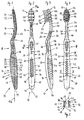
- FIG. Fig. 1 to Fig. 4 A first variant of a toothbrush body 10 according to the invention is shown in FIG Fig. 1 to Fig. 4 shown.
- the toothbrush body 10 is composed of three, one after the other along a longitudinal axis 11a extending in its longitudinal axis 11a arranged, in the embodiment shown integrally connected parts, namely a head portion 12, a neck portion 14 and a handle portion 16, together.
- the handle member 16 is in turn divided into a thumb support portion 18 and a palm support portion 20.
- Bristles 22 which project from a bristle receiving side 24 of the head portion 12 and together with the toothbrush body 10 form a toothbrush 26 are in Fig. 3 shown.
- the head part 12 has a length of 20 mm to 40 mm. This corresponds to 10% to 20% of the total length of the toothbrush 26.
- the slightly curved neck portion 14 extends from the head portion 12 to the handle portion 16 over a length of 20 mm to 60 mm, which is a range of 20% to 30% of the total length of the toothbrush 26 corresponds.
- the handle portion 16 extends from the neck portion 14 to the free end of the handle portion 16 over a length of 80 mm to 120 mm, ie 40% to 60% of the total length of the toothbrush 26.
- the thumb rest portion 18 and the palm support portion 20 have a length of 20 mm 60 mm or from 60 mm to 120 mm.
- the thickness of the toothbrush body 10 measures 5 mm to 15 mm perpendicular to the longitudinal axis 11a.
- the thickness of the palm support portion 20 is larger for ergonomic reasons and is 7 mm to 20 mm. This results in an advantageous Thickness ratio between the thumb rest portion 18 and the palm rest portion 20 of 1.2 to 4.
- the toothbrush body 10 is bounded by an upper side 28, comprising the bristle receiving side 24, an underside 30 opposite the upper side 28, and two broad sides 32 extending from the upper side 28 to the lower side 30.
- toothbrush body 10 All embodiments of the toothbrush body 10 described below each have an in FIG. 6 to FIG. 10 and in Fig. 19 to Fig. 23 shown basic structure 33 of a hard component 34 which at least partially carries a soft component 36.
- the hard component 34 is marked by a crosshatch and the soft component 36 by a simple oblique hatching.
- embodiments that are made solely from a hard component 34 or a soft component 36 or combinations of a number of hard components 34 and a number of soft components 36 are possible.
- the palm support portion 20 with nine recesses 37 in the form of through holes 38, which extend from the top 28 to the bottom 30 and thus completely penetrate the handle portion 16, provided.
- the holes 38 are arranged at regular intervals one behind the other and thereby form a straight row of holes 40.
- the row of holes 40 is enclosed between two, on the outer surface almost smooth longitudinal support strip 42.
- the longitudinal support strips 42 extend from Thumb rest portion 18 up to a blunt end portion 44 of the palm support portion 20.
- the holes 38 have oval cross-sections whose diameter from the center of the palm support portion 20 with respect to the longitudinal axis 11a in both directions with increasing distance from the center.
- recesses 37 in the palm support section 20 offers a number of advantages, in particular ergonomic advantages, since the hand relieves the toothbrush 26 at certain points and thereby ensures better circulation of the palm, and hygienic benefits by water, especially contaminated with bacteria or food residues, can be better removed from the handle portion 16 during a cleaning and subsequent cleaning process, which in turn increases the grip of the toothbrush 26.
- Economical advantages result above all from the fact that the material costs for the hard component 34 and the soft component 36 are reduced due to the lower use of material, and from a process engineering point of view there are advantages in particular in that during the production, which preferably takes place in an injection molding process, preference is given to tools, form the mutually supporting, slightly intermeshing cores are used and therefore no so-called blind holes occur.
- the ratio of the total volume of all the recesses 37 to the volume of the total surrounding palm support section 20 is less than 2: 1.
- the holes 38 preferably have a greater extent in a direction perpendicular to the longitudinal axis 11a.
- a rounding radius is less than 2 mm or the holes 38 have there an opening angle between 10 ° and 45 °.
- Fig. 3 shown in the soft component 36 wedge-shaped indentations 54 on the broad sides 32 in the Palm support portion 20, oval nubs 56 on the bottom 30 and the top 28 in the thumb rest section 18 and both sides embedded or raised support elements 58 in the boundary region between the thumb support portion 18 and palm support portion 20 formed.
- the indentations 54, nubs 56 and support members 58 serve to impart a secure hold of the toothbrush 26 in the hand of their user and lead with their contours geometric shapes of the recesses 37 on the palm support section 20 also continues.
- regions on the upper side 28 and the lower side 30 of the cross-sectionally substantially rectangular thumb rest section 18 are formed in the neck part 14. At the broad sides 32 of the neck portion 14, these areas are separated from the hard component 34 by a wavy boundary 60, as in FIG Fig. 3 shown, isolated.
- all regions filled with the soft component 36 are through channels, such as a neck channel 45 (see FIG Fig. 2 ), in the hard component 34, so that a single injection point for the soft component 36 is sufficient in the manufacturing process.
- Further recesses 46 in the form of through holes with a similar oval cross section or a similar geometric character, such as the recesses 37 of the palm support portion 20, are smaller in the head part 12 again. In this way, the user is given an affinity between the configuration of the palm support section 20 and the haptic associated with it and the cleaning sensation in the mouth influenced by the further recesses 46.
- the character of the row of holes 40, 2 to 9, preferably 3 to 6 of the further recesses 46 are formed in the head part 12.
- the further recesses 46 have a maximum diameter perpendicular to the longitudinal direction of the head part 12 of a maximum of 5 mm. Preferably, however, their longitudinal extent is between 1 mm and 3 mm.
- the relationship between the Areas of the further recesses 46 on the upper side 28 and the entire surface of the bristle receiving side 24 should be less than 1: 2, preferably less than 1: 3.
- the further recesses 46 are preferably similar, as the recesses 37 aligned in the palm support portion 20 and thereby allow the same Entformungscardi for the tool halves in the manufacture.
- the further recesses 46 lead to a, in particular in 2 and FIG. 4 clearly visible segmentation of the head part 12 in transverse webs 50, on which at least one row of bristles 22 takes place.
- the further recesses 46 are at least partially covered by inclined bristles 22 and bristle bundles 52.
- inclined bristles 22 and bristle bundles 52 Preferably, so-called X-bundles or Bockbündel be used, in which each adjacent bristles 22 and bristle bundles 52 cross over the middle of another recess 46 or meet.
- the inclined bristle bundles 52 support an interdental cleaning, which means in particular also a cleaning of the interdental spaces.
- the bristles 22 of the X-bundles are longer than bristles 22 protruding at least approximately at right angles from the bristle receiving side 24 and can protrude beyond the surrounding bristles 22.
- the further recesses 46 in the head portion 12 allow a better flushing of the bristles 22 when cleaning the toothbrush 26 after use, as well as a variety of additional functions, such as the support of a tongue cleaning and massage of the oral cavity and gum.
- massage and tongue cleaning elements On the underside 30 of the head part 12 are for this purpose massage and tongue cleaning elements, as also in Fig. 3 shown tongue scraper knobs 62, formed from the soft component 36. They are used for tongue cleaning and gum massage.
- the massage and tongue cleaning elements preferably follow edges of possibly existing further recesses 46 or further borderlines between the soft component 36 and the hard component 34.
- Fig. 5 shows a cross section through the in Fig. 1 to Fig. 4 shown toothbrush body 10 along in Fig. 4
- the cross section through the grip part 16 has a substantially square shape with rounded corners and with a nearly rectangular cutout 64 corresponding to the cut hole 38.
- the cross section has a symmetry with respect to the longitudinal center plane 11.
- the cut longitudinal support strips 42 of the upper side 28 and a cut hole wall 48 are marked by their hatching as molded from the hard component 34, the broad side 32 is essentially formed by the soft component 36.
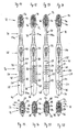
- FIGS. 6 to 10 is the supporting base structure 33 of the hard component 34 of in Fig. 1 to Fig. 5 shown toothbrush body 10.
- the basic structure 33 is subdivided into a head part element 12a, a neck part element 14a and a handle part element 16a, which in turn comprises a thumb rest element 18a and a palm rest element 20a.
- the sides delimiting them are also related to the sides of the toothbrush body 10 as a structural top 28a, referred to as structure bottom 30a and as structured broadsides 32a.
- the basic structure 33 has, as in particular in Fig. 8 Visible, a slightly curved handle plate 47, which forms at least almost the entire top 28 of the palm support portion 20 of the toothbrush body 10, including its head portion 12 facing away from the blunt end portion 44 and the longitudinal support strip 42 or. From the hard component 34 are also perforated walls 48 which extend at least approximately at right angles from the underside 30 facing side of the handle plate 47 upstanding to the bottom 30, and podium-like extensions 70, the straight line continuation of the row of holes 40 to the blunt end portion 44 at least almost at right angles from the underside 30 facing side of the handle plate 47 are arranged to projecting almost to the bottom 30, formed.
- this block-like part of the basic structure 33 permits proper support of the basic structure 33 with the recesses 37 contained therein between the mold halves of the injection molding tool , Less preferred is an embodiment in which the perforated walls 48 are singulated and not interconnected along the longitudinal axis of the palm rest 20a.
- a problem-free filling of the entire mold cavity with the hard component 34 the extends over the entire length of the toothbrush body 10 to allow and possible so-called sink marks to avoid, in addition to the recesses 37 forming block forming a passage for the first fluid hard component 34 to the neck member 14a and the head part element 12a with a cross section of at least 5 mm 2 , preferably of at least 10 mm 2 used.
- the thumb rest element 18a is formed as a bridge between the block-like and therefore stable palm support element 20a and the neck part element 14a, which is formed almost as a solid body.
- the thumb support element 18a is designed significantly wider with respect to the structure top side 28a or the structure bottom side 30a than with respect to the thickness with respect to the structured broad sides 32a.
- the thumb rest element 18a is provided on the upper structure side 28a with two rail-like webs 72 running parallel along the longitudinal axis of the thumb rest element 18a and slightly curved in the direction of the structure lower side 30a.
- the webs 72 are used for the lateral stable reception of the soft component 36 which lies above them and, since they can be felt by the soft component 36, allow a precise guidance of the toothbrush 26.
- the bridge-like design of the thumb support member 18a also ensures sufficient elasticity of the head portion 12 relative to the handle portion 16 and prevents excessive pressure pressure of the gums by the force transmitted to the bristles 22 forces.
- the basic structure 33 widens from the neck part element 14a, which adjoins the thumb support element 18a, in the manner of a spatula to the rounded head part element 12a.
- the further recesses 46 and a number of a hole field 74 forming blind holes 76 for receiving bristle bundles 52 are arranged.
- Fig. 10 is a cut through the in Fig. 9 shown palm support member 20a along the marked there cutting plane X - X shown.
- the sectional view shows the areas of the hard component 34 according to Fig. 5 , In this case, 38 symmetrical cut surfaces of the hole wall 48 and the handle plate 47 are visible with respect to the longitudinal axis of the cut hole.
- tops 28 of various toothbrush bodies 10 having different geometric shapes of holes 38 are shown.
- oval cross-sectional shape of holes 38 are more simple geometric basic shapes but also complex shape compositions in a continuous or interrupted series of holes 38 in a number of 3 to 30 pieces, but preferably from about 7 to 12 pieces possible.
- the cross-sectional shapes of the recesses 37 of the palm rest section 20 are changed in size resumed in the head part 12.
- holes 38 of different basic shapes can also be formed on a toothbrush body 10.
- Interruptions in rows of holes 38 are particularly suitable for the application of labels.
- such as in FIGS. 13 and 14 shown such a discontinuity in a central region of the palm support portion 20 is arranged.
- holes 38 have the shape of a parallelogram 78, the longitudinal sides include an angle with the longitudinal axis 11a.
- Fig. 12 is an arrowhead 80, in Fig. 13 a sickle 82, and in Fig. 14 a triangle 84 as a recurring, arranged in rows of holes 40 basic shape.
- the total area of a recess 37 on the upper side 28 is between 10 mm 2 - 200 mm 2 , preferably 20 mm 2 - 50 mm 2 . Due to the size and shape of the individual recesses 37, a trouble-flushing through the holes 38 for cleaning the toothbrush 26 is made possible and at the same time a capillary action for water and impurities excluded.
- the longitudinal axes of the basic shapes are preferably arranged at right angles to the longitudinal axis 11a.
- the minimum material thickness between two holes 38 of the palm support section 20 should not fall below 0.3 mm. For reasons of stability, it is preferably 0.8 mm to 3 mm.
- FIGS. 15 to 18 Further embodiments are shown with oval further recesses 46 in headboards 12.
- transverse webs 50 consist entirely of the soft component 36 or a combination of the hard component 34 and the soft component 36 and extending from the bristle receiving side 24 on the broad sides 32 to over the bottom 30 of the head portion 12.
- the segments formed are mutually flexibly deflectable.
- the flexibility is achieved by a targeted weakening of the hard component 34 between the transverse webs 50 to form hinge-like transition zones. If the material weakening takes place only in the hard component 34, then a minimum material thickness of less than 2 mm, preferably less than 1.5 mm, is recommended. Preferably, however, the material weakening is in a composite region of hard component 34 and soft component 36. Alternatively, however, lateral openings or tunnels may be formed in the transition zones during the production process by means of lateral slides and subsequently filled with the soft component 36.
- the soft component 36 is in Fig. 15 slightly offset by 0.1 mm to 1 mm from the hard component 34.
- substantially stepless transitions between the hard component 34 and the soft component 36 may also be formed, effectively preventing accumulation of dirt and water at the junctions.
- the layer thickness ratio of the soft component 36 to the hard component 34 is preferably less than 1: 3.
- FIGS. 16 to 18 on the bristle receiving side 24 rubber-elastic, formed from the soft component 36 cleaning and massage elements 86 and / or rows of fixed in the blind holes 76 bristles 22 are mounted.
- the cleaning and massage elements 86 or rows of bristles are arranged between the further recesses 46 in the head part 12 and / or between bristle bundles 52. They generally have a greater extent at right angles to the longitudinal axis of the head part 12 than in the direction parallel to this longitudinal axis.
- the cleaning and massage elements 86 and bristle rows substantially at least partially edges of the other recesses 46 follow.
- the distance between the edges of the further recesses 46 and the related cleaning and massage elements 86 or bristle rows is less than 2 mm, preferably less than 1.2 mm.
- bristle methods are preferred which can produce 52 thin rows of bristles 22 in addition to the classic bristle bundles 52.
- IMT in-mold tufting
- AFT anchor free tufting technique
- Bristles 22 carrying bristle carrier plates 88 are mounted on the bristle receiving side 24 of the head part 12.
- the bristle carrier plate 88 is a form-fitting tight in a corresponding recess of the head portion 12 and is glued or welded in this, to prevent ingress of water or contaminants in the recess.
- bundles of bristles 52 manufactured using a conventional stuffing method for a blind hole diameter of less than 1.6 mm can be strung together.
- FIGS. 19 to 23 a further embodiment of a base structure 33 formed from the hard component 34 for a second variant of the toothbrush body 10 is presented. It is equipped with an elongate, plate-like handle web 90 which extends along the longitudinal mid-plane 11 in the palm support section 20 between the top 28 and the bottom 30 from the thumb rest section 18 to the blunt end region 44 of the palm rest section 20. At its middle part, the handle web 90 protruding, the underside 30 of the toothbrush body 10 facing stumps 94.
- the grip web 90 has a thickness of 4 mm to 8 mm measured perpendicular to the longitudinal center plane 11. It tapers structurally on top and forms on the upper side 28 of the toothbrush body 10 (see Fig. 24 to Fig. 27 Due to the plate-like shape of the handle web 90 of the palm support portion 20 of the toothbrush body 10 receives a dependent on the thickness of the handle bar 90 flexibility so that it is perpendicular to the user Longitudinal center plane 11 can be deflected and the handle part 16 optimally adapts to specific hand shapes of right and left-handers. Flexibility in a direction parallel to the longitudinal center plane 11 is substantially prevented by the height of the grip web 90 of 10 mm to 15 mm.
- the grip web 90 has three, in the direction of the structure bottom 30a projecting stumps 94.
- the stumps 94 are used for encapsulation with the soft component 36 for holding the base structure 33 in the mold halves.
- the thumb rest member 18a is formed substantially perpendicular to the longitudinal center plane 11 substantially oval and tapers along the side waist-like in its two end regions.
- the cross section of the thumb support member 18a thickened along the longitudinal center plane 11 toward its two end regions.
- one elongated hole 96 which is continuous from the upper structure side 28a to the lower structure side 30a, is each extracted.
- the neck part element 14a extends as a slightly bow-like shaped solid body up to the head part element 12a, where it widens like a spatula for receiving bristles 22.
- FIGS. 20 to 22 On the neck part 14a, following the thumb rest element 18a, four partially circumferential neck grooves 98 are formed. These neck grooves 98 in turn form neck ribs 100 which are filled with the soft component 36 on the toothbrush body 10 are (see Fig. 25 to Fig. 27 ).
- Fig. 20 On the structure lower side 30a a further embodiment of the open neck channel 45 is shown.
- gap-like further recesses 46 are formed, which will be discussed in detail in connection with the following description of the associated toothbrush body 10.
- Fig. 23 shows a cross section along the line XXIII - XXIII by the in FIGS. 19 to 22 shown basic structure 33 on the thumb rest element 18a. In this case, two oval cut surfaces of the hard component 34, which are spaced from each other by the slot 96, are shown.
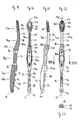
- Fig. 24 to Fig. 27 is an embodiment of the toothbrush body 10, by the application of the soft component 36 on the in Fig. 19 to Fig. 23 shown basic structure 33 has been completed presented.
- Fig. 25 to Fig. 27 Particularly well visible, it has in the palm support portion 20 recesses 37 in the form of open at the broad side 32 lateral recesses 102, which pass from the top 28 to the bottom 30 on.
- the recesses 102 adjoin the upper side 28 on the longitudinal support strips 42 formed from the hard component 34 (see FIG Fig. 27 ).
- the recesses 102 are continuous from the top 28 to the bottom 30 over a depth of up to 7 mm.
- Fig. 25 are shown on the underside 30 in the palm support portion 20 each have two, with respect to the longitudinal center plane 11 opposite lateral recesses 102 open by means of a bottom 30, for improved ergonomics preferably M-shaped corrugated lower recess 103 connected.
- a plurality of groove-shaped lateral and lower recesses 102, 103 arranged one behind the other in the longitudinal direction of the palm support section 20 form ribs 104 out of the soft component 36, projecting from bottoms 106 of the lateral and lower recesses 102, 103. Edges of the ribs 104 are rounded.
- FIGS. 25 and 27 are the ribs 104 at the broad sides 32 obliquely to the longitudinal center plane 11 and include an acute, measured in the direction of the blunt end portion 44 angle of preferably 45 °.
- the ribs 104 formed from the soft component 36 are laterally flexible and optimally adapt to the user's hand.
- the width of the ribs 104 measured parallel to the longitudinal axis 11a is 2 mm to 10 mm, preferably 5 mm.
- the width of the bottoms 106 of the recesses 102 and the lateral spacing of the ribs 104 are smaller than the outer width of the ribs 104 on the broadsides 32.
- the lateral and lower recesses 102, 103 are circumferentially spaced about 95%, but at least 75% of the radial circumference and interrupted along the longitudinal axis 11a on the upper surface 28 by the longitudinal support strip 42.
- the lateral and lower recesses 102, 103 form drainage channels through which water can flow from the palm of the hand during the cleaning process.
- the lateral recesses 102 which are open toward the broad sides 32 are formed during the production process by standing cores of the mold halves which meet substantially in the center of the workpiece.
- the lateral recesses 102 are also all oriented in a Entformungscardi, so that in the manufacture of the toothbrush body 10 preferably no additional side shifters must be used.
- the substantially fir-cone-shaped palm support portion 20 shown is except for the longitudinal support strip 42, the blunt end portion 44 and the outer surfaces of the stumps 94 (see Fig. 25 ) the majority of the surface of the soft component 36 is formed.
- the volume ratio of the hard component 34 to the soft component 36 in this section is less than 1: 2, preferably about 1: 3.
- a label may be mounted on the broad side 32 of the thumb rest section 18. It is formed in the manufacturing process by means of running side slides directly during injection molding or in a hot stamping process, which is preferably carried out during the bristling process. Preferably, mold parting surfaces or edges in the labeling field are avoided by displaced slides in this area or staggered mold halves.
- the head portion 12 each of the broadsides 32 beginning 6 more Recesses 46 in the form of further recesses 105 and thus assumes the geometric character of the palm support portion 20 at.
- formed lateral head ribs 108 also open at an acute angle with respect to the longitudinal axis of the head portion 12 toward the handle portion 16 back.
- the opening angle between the individual header ribs 108 may vary.
- the depth of the further recesses 105 in the head part 12 is less than 5 mm, preferably between 0.3 mm and 3 mm, measured from the broad sides 32 of the head part 12. They do not pass through the longitudinal axis of the head part 12. Similar to the lateral and lower recesses 102, 103 in the palm support section 20, the further recesses 105 and thus also the head section ribs 108 are not formed completely circumferentially. On the bottom 30 of the headboard 12 they end, as in Fig. 25 shown on a head longitudinal strip 110.
- each broad side 32 5 header ribs 108 have on the bristle receiving side 24 at least one width, which is sufficient to receive a bristle bundle 52.
- the head part ribs 108 consist of a combination of the hard component 34 and the soft component 36.
- the soft component 36 is preferably with a layer thickness between 0.3 mm to 3 mm, preferably about 1 mm, on the bristle receiving side 24 and on the entire underside 30 of the head part 12 is inserted into the head part 12. In this way, an attachment of Dirt prevents in the transition region between the hard component 34 and the soft component 36.
- the layer of soft component 36 on the bristle receiving side 24 is slightly raised.
- the flexibility of the head part ribs 108 can be influenced via the layer thickness of the soft component 36. It is also conceivable, for example, their complete molding with the soft component 36. Alternatively, a profile of layer thicknesses of the soft component 36 may be provided. In this case, for example, the profile could increase towards the outside and thereby increase the flexibility of the head part ribs 108.
- the bristles 22 are anchored in blind holes 76 of the basic structure 33 and completely penetrate the layer of the soft component 36, respectively.
- Fig. 27 shows two continuous, preferably film-like sub-surfaces 112 formed from the soft component 36. Alternatively, however, only one or up to five sub-surfaces 112 can be formed from the soft component 36.
- the soft component 36 is supplied to these areas forming the sub-surfaces 112 by head part channels, not shown, starting from the underside 30 of the head part 12. A material connection via the broad sides 32 of the head part 12 is not necessary.
- Protruding from and anchored in the sub-surfaces 112 may also be made of the soft component 36 be formed rubber-elastic cleaning and massage elements 86.
- slides are also used in this embodiment in the production of the further recesses 46 in the head part 12, in the event that the further recesses 46 are angled relative to the grip part 16.
- the further recesses 46 in the head part 12 and the bristle bundle 52 receiving hole field 74 are preferably designed such that in their preparation, the Entformungscardi the mold halves is substantially equal and thus the same slide mechanism can be used.
- the bristles 22 or bristle bundles 52 may be aligned obliquely with respect to the further recesses 46, as in previously described embodiments, around the further recesses 46 in the head part 12.
- massage and tongue cleaning elements such as the tongue scraper nubs 62, may be attached to the underside 30 of the head portion 12, preferably adjacent to or adjacent edges of the further recesses 46 and / or the transverse webs 50.
- the mold halves Prior to injecting the hard component 34, the mold halves are brought together to form standing cores so as to meet substantially at the center of the mold volume. During the subsequent spraying of the soft component 36, cores and / or slides may only partially be inserted into the hard component 34.
- toothbrush bodies 10 or toothbrushes 26 prove to be advantageous, in which the recesses 37 and further recesses 46 are similarly oriented in a demoulding direction.
- the orientation and the arrangement as well as the size and shape of the recesses 37 and the further recesses 46 thereby determine the flexibility of the finished toothbrush 26.
- the flexibility is also determined by the material composition of the toothbrush 26.
- the hard component 34 is made, for example, of styrene-acrylonitrile (SAN), polyester (PET), polymethylmethacrylate (PMMA), acrylobutadiene-styrene (ABS), but preferably of polypropylene (PP).
- SAN styrene-acrylonitrile
- PET polyester
- PMMA polymethylmethacrylate
- ABS acrylobutadiene-styrene
- PP polypropylene
- a soft component 36 is a rubber-elastic material such as, polyurethane (PUR), preferably a thermoplastic elastomer (TPE) or a thermoplastic polyurethane (TPU) is used.
- PUR polyurethane
- TPE thermoplastic elastomer
- TPU thermoplastic polyurethane
Landscapes
- Brushes (AREA)
- Massaging Devices (AREA)
Claims (18)
- Corps de brosse à dents, qui présente, le long d'un axe longitudinal (11a) s'étendant dans son plan médian longitudinal (11), successivement, une partie de tête (12) avec un côté de réception des poils (24), une partie de col (14) et une partie de préhension (16), qui se divise en une portion d'appui pour le pouce (18) tournée vers la partie de col (14) et une portion d'appui pour la paume de la main (20) qui se raccorde à la portion d'appui pour le pouce (18), le corps de brosse à dents (10) étant limité par un côté supérieur (28), comprenant le côté de réception des poils (24), un côté inférieur (30) opposé au côté supérieur (28), et deux côtés larges (32) s'étendant depuis le côté supérieur (28) jusqu'au côté inférieur (30), et la portion d'appui pour la paume de la main (20) étant formée d'au moins un composant dur (34) et d'au moins un composant mou (36), caractérisé en ce que du côté supérieur (28) de la portion d'appui pour la paume de la main (20) au moins une bande d'appui longitudinale (42) s'étendant au moins pratiquement parallèlement à l'axe longitudinal (11a) est formée, à côté de laquelle se trouve, latéralement, au moins une exclusion (37) continu depuis le côté supérieur (28) jusqu'au côté inférieur (30).
- Corps de brosse à dents selon la revendication 1, caractérisé en ce que le composant dur (34) est fabriqué en un plastique dur, de préférence du polypropylène, et le composant mou (36) en un plastique plus mou, élastique, de préférence un élastomère thermoplastique.
- Corps de brosse à dents selon la revendication 1 ou 2, caractérisé en ce que l'exclusion (37) est réalisé entre deux bandes d'appui longitudinales (42) sous forme de trou (38) passant à travers l'axe longitudinal (11a).
- Corps de brosse à dents selon la revendication 3, caractérisé en ce qu'au moins deux trous (38) sont disposés entre deux bandes d'appui longitudinales (42) en forme de rangée de trous rectiligne (40) le long de l'axe longitudinal (11a).
- Corps de brosse à dents selon l'une quelconque des revendications 1 à 4, caractérisé en ce qu'au moins une plaque de préhension légèrement cintrée (47), qui forme pratiquement tout le côté supérieur (28) de la portion d'appui pour la paume de la main (20), y compris sa région d'extrémité (44) émoussée opposée à la partie de tête (12) et la ou les bandes d'appui longitudinales (42), ainsi que des parois perforées (48), qui s'étendent au moins pratiquement perpendiculairement au côté de la plaque de préhension (47) tourné vers le côté inférieur (30), en saillie jusqu'au côté inférieur (30), et des saillies en forme de plate-forme (70), qui sont disposées dans le prolongement rectiligne de la rangée de perforations (40) jusqu'à la région d'extrémité émoussée (44), au moins presque perpendiculairement au côté de la plaque de préhension (47) tourné vers le côté inférieur (30), en saillie pratiquement jusqu'au côté inférieur (30), sont façonnées dans le composant dur (34), et le composant dur (34) sert de structure porteuse de base (33) pour le composant mou (36), qui remplit le volume restant de la portion d'appui pour la paume de la main (20) jusqu'aux côté larges (32) et au côté inférieur (30).
- Corps de brosse à dents selon la revendication 1, caractérisé en ce que l'exclusion (37) est réalisé sous forme d'évidement (102) latérale ouverte au niveau du côté large (32) et adjacente aux bandes d'appui longitudinales (42).
- Corps de brosse à dents selon la revendication 6, caractérisé en ce qu'à chaque fois au moins deux évidements latérals (102) de préférence opposées l'une à l'autre par rapport au plan médian longitudinal (11), sont connectées au moyen d'un évidement inférieur (103) en forme de M de préférence par rapport au côté inférieur (30), ouverte au niveau du côté inférieur (30), sur le côté inférieur (30) de la portion d'appui pour la paume de la main (20).
- Corps de brosse à dents selon la revendication 7, caractérisé en ce que plusieurs évidements latérals et/ou inférieurs (102, 103) disposées les unes derrière les autres le long de l'axe longitudinal (11a) forment des nervures (104) qui font saillie depuis les fonds (106) des évidements latérales et/ou inférieures (102, 103).
- Corps de brosse à dents selon la revendication 8, caractérisé en ce que les nervures (104) sont disposées obliquement par rapport à l'axe longitudinal (11a).
- Corps de brosse à dents selon la revendication 8 ou 9, caractérisé en ce que le composant dur (34), dans la structure de base (33), forme une âme de préhension allongée (90), qui s'étend le long du plan médian longitudinal (11) dans la portion d'appui pour la paume de la main (20) entre le côté supérieur (28) et le côté inférieur (30) depuis la portion d'appui pour le pouce (18) jusqu'à une région d'extrémité émoussée (44) de la portion d'appui pour la paume de la main (20) et présente des bosselures (94) saillant au niveau de sa partie centrale, tournée vers le côté inférieur (30), cette âme de préhension (90) portant le composant mou (36) qui constitue les nervures (104).
- Corps de brosse à dents selon l'une quelconque des revendications 1 à 10, caractérisé en ce que la ou les bandes d'appui longitudinales (42) est ou sont formées par le composant dur (34).
- Corps de brosse à dents selon l'une quelconque des revendications 1 à 11, caractérisé en ce que le composant dur (34) s'étend depuis la région d'extrémité émoussée (44) de la portion d'appui pour la paume de la main (20) par-dessus la portion d'appui pour le pouce (18) et la partie de col (14) jusqu'à à l'extrémité libre la plus extérieure de la partie de tête (12).
- Corps de brosse à dents selon l'une quelconque des revendications 1 à 12, caractérisé en ce que la portion d'appui pour le pouce (18) et/ou la partie de col (14) et/ou la partie de tête (12) sont également pourvues d'autres exclusions (46) avec une forme géométrique similaire, comme les exclusions respectifs (37) sur la portion d'appui pour la paume de la main (20).
- Brosse à dents comprenant un corps de brosse à dents (10) selon l'une quelconque des revendications 1 à 13, caractérisée en ce que le corps de brosse à dents (10) est garni au niveau de la partie de tête (12) de poils (22) rassemblés en touffes de poils (52).
- Brosse à dents selon la revendication 14, caractérisée en ce que les poils (22) et/ou les touffes de poils (52) font saillie en forme de X les uns par rapport aux autres de manière inclinée depuis le côté de réception des poils (24) de la partie de tête (12).
- Brosse à dents selon la revendication 14 ou 15, caractérisée en ce que la partie de tête (12) est munie d'éléments de nettoyage et de massage (86).
- Brosse à dents selon la revendication 16, caractérisée en ce que les éléments de nettoyage et de massage (86) sont appliqués en se raccordant ou en position adjacente aux bords d'autres exclusions (46) et/ou plages transversales (50).
- Brosse à dents selon l'une quelconque des revendications 14 à 17, caractérisée en ce que la flexibilité prédéterminée de la brosse à dents (26) est obtenue par une composition définie du matériau et/ou un affaiblissement de matériau, c'est-à-dire une dimension, une forme, et une orientation appropriées des exclusions (37) et d'autres exclusions (46).
Priority Applications (5)
| Application Number | Priority Date | Filing Date | Title |
|---|---|---|---|
| AT04018191T ATE433687T1 (de) | 2004-07-31 | 2004-07-31 | Zahnbürste mit ausnehmungen |
| DE502004009613T DE502004009613D1 (de) | 2004-07-31 | 2004-07-31 | Zahnbürste mit Ausnehmungen |
| EP04018191A EP1621105B1 (fr) | 2004-07-31 | 2004-07-31 | Brosse à dents avec cavités |
| PCT/EP2005/005858 WO2006012938A2 (fr) | 2004-07-31 | 2005-06-01 | Brosse a dents presentant des evidements |
| US11/658,915 US8046864B2 (en) | 2004-07-31 | 2005-06-01 | Toothbrush with recesses |
Applications Claiming Priority (1)
| Application Number | Priority Date | Filing Date | Title |
|---|---|---|---|
| EP04018191A EP1621105B1 (fr) | 2004-07-31 | 2004-07-31 | Brosse à dents avec cavités |
Publications (2)
| Publication Number | Publication Date |
|---|---|
| EP1621105A1 EP1621105A1 (fr) | 2006-02-01 |
| EP1621105B1 true EP1621105B1 (fr) | 2009-06-17 |
Family
ID=34926019
Family Applications (1)
| Application Number | Title | Priority Date | Filing Date |
|---|---|---|---|
| EP04018191A Expired - Lifetime EP1621105B1 (fr) | 2004-07-31 | 2004-07-31 | Brosse à dents avec cavités |
Country Status (5)
| Country | Link |
|---|---|
| US (1) | US8046864B2 (fr) |
| EP (1) | EP1621105B1 (fr) |
| AT (1) | ATE433687T1 (fr) |
| DE (1) | DE502004009613D1 (fr) |
| WO (1) | WO2006012938A2 (fr) |
Families Citing this family (72)
| Publication number | Priority date | Publication date | Assignee | Title |
|---|---|---|---|---|
| DE102006005616A1 (de) * | 2006-02-06 | 2007-08-09 | Synpart Ag | Reinigungs-oder Applikationsgerät |
| ITRM20070228U1 (it) * | 2007-01-30 | 2008-07-31 | Banat Firca Ve Plastik Sanayi | Spazzolino da denti con corpo e collo fessurati |
| DE102007017869A1 (de) * | 2007-04-13 | 2008-10-16 | Braun Gmbh | Zahnbürste |
| USD621621S1 (en) | 2007-04-23 | 2010-08-17 | The Procter & Gamble Company | Toothbrush |
| USD666005S1 (en) | 2008-04-21 | 2012-08-28 | Braun Gmbh | Portion of a toothbrush handle |
| EP2181621A1 (fr) | 2008-10-28 | 2010-05-05 | Braun Gmbh | Brosse à dents |
| EP2759227B1 (fr) * | 2009-03-18 | 2016-10-05 | Braun GmbH | Brosse à dents |
| US20110078867A1 (en) * | 2009-10-01 | 2011-04-07 | Michael Liangco | Flexible toothbrush |
| EP2509463B8 (fr) * | 2009-12-10 | 2019-09-04 | Braun GmbH | Brosse à dents |
| USD654695S1 (en) | 2009-12-18 | 2012-02-28 | Colgate-Palmolive Company | Toothbrush |
| USD632484S1 (en) | 2009-12-18 | 2011-02-15 | Eduardo Jimenez | Toothbrush handle with tissue cleaner |
| US8549691B2 (en) * | 2009-12-18 | 2013-10-08 | Colgate-Palmolive Company | Oral care implement having multi-component handle |
| USD675830S1 (en) | 2009-12-18 | 2013-02-12 | Colgate-Palmolive Company | Toothbrush |
| USD654696S1 (en) | 2009-12-18 | 2012-02-28 | Colgate-Palmolive Company | Toothbrush handle with tissue cleaner |
| MX350998B (es) * | 2009-12-18 | 2017-09-27 | Colgate Palmolive Company Star | Implemento para el cuidado oral con mangos de componentes múltiples. |
| CN104248213B (zh) * | 2009-12-18 | 2016-05-18 | 高露洁-棕榄公司 | 具有多构件手柄的口腔护理器具 |
| USD654270S1 (en) | 2009-12-18 | 2012-02-21 | Colgate-Palmolive Company | Toothbrush handle |
| USD657569S1 (en) * | 2010-02-26 | 2012-04-17 | Colgate-Palmolive Company | Head portion of an oral care implement |
| US20110225755A1 (en) * | 2010-03-18 | 2011-09-22 | Ecolab Usa Inc. | Cleaning tool |
| USD671746S1 (en) * | 2010-05-05 | 2012-12-04 | Colgate-Palmolive Company | Head portion of a toothbrush |
| US8387195B2 (en) * | 2010-10-28 | 2013-03-05 | Ashtel Studios Inc. | Educational toothbrush |
| USD675448S1 (en) * | 2010-12-21 | 2013-02-05 | Colgate-Palmolive Company | Oral care implement |
| USD675831S1 (en) | 2010-12-21 | 2013-02-12 | Colgate-Palmolive Company | Oral care implement |
| RU2534065C1 (ru) * | 2010-12-21 | 2014-11-27 | Колгейт-Палмолив Компани | Устройство для ухода за полостью рта |
| KR101548839B1 (ko) * | 2010-12-21 | 2015-08-31 | 콜게이트-파아므올리브캄파니 | 구강 관리 기구 |
| USD675447S1 (en) * | 2010-12-21 | 2013-02-05 | Colgate-Palmolive Company | Oral care implement |
| WO2012093085A2 (fr) * | 2011-01-04 | 2012-07-12 | Trisa Holding Ag | Brosse à dents comportant des soies injectées et procédé et dispositif pour fabriquer une telle brosse à dents |
| GB201104024D0 (en) * | 2011-03-09 | 2011-04-20 | Glaxosmithkline Consumer Healt | Novel device |
| US20130000658A1 (en) * | 2011-07-01 | 2013-01-03 | Mizaru Enterprises, LLC | Combination Toothbrush, Floss Dispenser and Tongue Scraper |
| EP2554353B1 (fr) * | 2011-08-05 | 2017-06-07 | Trisa Holding AG | Procédé de fabrication d'une brosse à dents et brosse à dents |
| US8561248B2 (en) | 2011-08-25 | 2013-10-22 | King Saud University | Flexible, ergonomic toothbrush with replaceable bristles |
| US20130333134A1 (en) * | 2012-06-13 | 2013-12-19 | Buta Herr | Toothbrush Head and Ergonomic Toothbrush Handle |
| USD724324S1 (en) * | 2012-06-20 | 2015-03-17 | Braun Gmbh | Toothbrush head with tongue cleaner |
| USD672149S1 (en) | 2012-07-03 | 2012-12-11 | Ranir, Llc | Portion of a toothbrush |
| MX365145B (es) * | 2013-03-28 | 2019-05-24 | Colgate Palmolive Co | Implemento del cuidado oral. |
| EP3223657B1 (fr) | 2014-12-23 | 2022-12-07 | Colgate-Palmolive Company | Accessoire de soins buccaux |
| US10455931B2 (en) | 2014-12-23 | 2019-10-29 | Colgate-Palmolive Company | Oral care implement |
| WO2016105374A1 (fr) | 2014-12-23 | 2016-06-30 | Colgate-Palmolive Company | Instrument de soin buccal |
| EP3995036B1 (fr) | 2014-12-23 | 2025-06-04 | Colgate-Palmolive Company | Ustensile de soin buccal |
| EP3223655B1 (fr) | 2014-12-23 | 2024-10-09 | Colgate-Palmolive Company | Instrument de soin buccal |
| CA2970634C (fr) | 2014-12-23 | 2022-04-12 | Colgate-Palmolive Company | Ustensile pour l'hygiene bucco-dentaire comportant un manche a elements multiples |
| US11291293B2 (en) | 2014-12-23 | 2022-04-05 | Colgate-Palmolive Company | Oral care implement |
| USD780457S1 (en) | 2014-12-23 | 2017-03-07 | Colgate-Palmolive Company | Oral care implement |
| RU2664278C1 (ru) | 2014-12-23 | 2018-08-15 | Колгейт-Палмолив Компани | Устройство для ухода за полостью рта, содержащее многокомпонентную ручку |
| BR112017010792B1 (pt) | 2014-12-23 | 2021-10-05 | Colgate-Palmolive Company | Instrumento de higiene bucal |
| MX393731B (es) | 2014-12-23 | 2025-03-24 | Colgate Palmolive Co | Implemento para el cuidado bucal. |
| US10660430B2 (en) | 2014-12-23 | 2020-05-26 | Colgate-Palmolive Company | Oral care implement having multi-component handle |
| US9072369B1 (en) * | 2014-12-26 | 2015-07-07 | Cyrus Shokoohi | Oral care implement |
| USD780458S1 (en) * | 2015-01-16 | 2017-03-07 | Radius Corporation | Toothbrush |
| US9802347B2 (en) | 2015-02-02 | 2017-10-31 | Colgate-Palmolive Company | Method of forming an oral care implement |
| AU364475S (en) * | 2015-03-27 | 2015-09-30 | Colgate Palmolive Co | Oral care implement |
| USD762987S1 (en) * | 2015-06-30 | 2016-08-09 | Deotech Korea Co., Ltd. | Toothbrush |
| WO2017012109A1 (fr) | 2015-07-23 | 2017-01-26 | Colgate-Palmolive Company | Outil de soin buccal |
| USD777446S1 (en) * | 2015-07-23 | 2017-01-31 | Colgate-Palmolive Company | Oral care implement handle |
| USD776937S1 (en) | 2015-07-23 | 2017-01-24 | Colgate-Palmolive Company | Oral care implement |
| USD778062S1 (en) * | 2015-08-06 | 2017-02-07 | The Gillette Company Llc | Toothbrush |
| US20170347785A1 (en) * | 2016-06-03 | 2017-12-07 | Acumen Co., Ltd. | Toothbrush head |
| USD851406S1 (en) * | 2016-08-11 | 2019-06-18 | M+C Schiffer Gmbh | Toothbrush |
| US10709533B2 (en) | 2017-12-12 | 2020-07-14 | Colgate-Palmolive Company | Oral care implement and handle and refill head thereof |
| US10631964B2 (en) | 2017-12-12 | 2020-04-28 | Colgate-Palmolive Company | Oral care implement |
| USD846883S1 (en) | 2017-12-12 | 2019-04-30 | Colgate-Palmolive Company | Handle of an oral care implement |
| USD874832S1 (en) * | 2018-03-23 | 2020-02-11 | Israel Harry Zimmerman | Toothbrush handle |
| USD876097S1 (en) * | 2018-03-23 | 2020-02-25 | Israel Harry Zimmerman | Toothbrush handle |
| USD891784S1 (en) | 2018-12-18 | 2020-08-04 | Colgate-Palmolive Company | Electric toothbrush handle |
| EP3804560A1 (fr) * | 2019-10-09 | 2021-04-14 | Trisa Holding AG | Produit d'hygiène buccale |
| US11800924B2 (en) * | 2019-12-03 | 2023-10-31 | Colgate-Palmolive Company | Oral care implement |
| US11350729B2 (en) * | 2019-12-03 | 2022-06-07 | Colgate-Palmolive Company | Oral care implement |
| USD960582S1 (en) | 2020-12-10 | 2022-08-16 | Colgate-Palmolive Company | Oral care refill head |
| US20220361655A1 (en) * | 2021-05-14 | 2022-11-17 | Colgate-Palmolive Company | Personal Care Implement |
| US11877645B2 (en) | 2021-05-14 | 2024-01-23 | Colgate-Palmolive Company | Personal care implement |
| USD1029506S1 (en) | 2021-12-30 | 2024-06-04 | Colgate-Palmolive Company | Toothbrush |
| USD1108813S1 (en) | 2024-04-04 | 2026-01-13 | Trisa Holding Ag | Toothbrush handle |
Family Cites Families (16)
| Publication number | Priority date | Publication date | Assignee | Title |
|---|---|---|---|---|
| US1840246A (en) | 1927-09-24 | 1932-01-05 | Philip S Newman | Toothbrush |
| US1860924A (en) | 1931-05-18 | 1932-05-31 | Cooke Rupert George | Toothbrush |
| US2263885A (en) * | 1940-05-09 | 1941-11-25 | Walter G Mcgauley | Toothbrush |
| DE3820372C2 (de) | 1988-06-15 | 1997-07-24 | Coronet Werke Gmbh | Verfahren und Vorrichtung zur Herstellung von Borstenwaren |
| US5272784A (en) * | 1991-08-12 | 1993-12-28 | Levin Samuel N | Toothbrush handle |
| DE4222931C1 (de) | 1992-07-11 | 1993-12-09 | Henkel Kgaa | Zahnbürste |
| GB9515596D0 (en) | 1995-07-29 | 1995-09-27 | Mariax Ltd | Toothbrush |
| USD377715S (en) * | 1996-05-01 | 1997-02-04 | Baldwin Deanna L | Disposable toothbrush |
| US6308367B1 (en) * | 1997-11-12 | 2001-10-30 | Gillette Canada Company | Toothbrush |
| US6292973B1 (en) | 1999-04-29 | 2001-09-25 | Robert Moskovich | Toothbrush having controlled head movement |
| GB2350054A (en) * | 1999-05-18 | 2000-11-22 | Nathan Lee Whitman | Oral hygiene implements |
| US6286173B1 (en) | 1999-09-30 | 2001-09-11 | Nick Walter Alcantara Briones | 2-head toothbrush with surehold |
| US6553604B1 (en) * | 2000-03-16 | 2003-04-29 | Gillette Canada Company | Toothbrush |
| DE20006311U1 (de) | 2000-04-06 | 2001-08-09 | G.B. Boucherie N.V., Izegem | Vorrichtung zum Befestigen von mit Borstenbüscheln versehenen Plättchen an Bürstenkörpern |
| GB0014495D0 (en) * | 2000-06-15 | 2000-08-09 | Smithkline Beecham Gmbh & Co | Process |
| FR2813170B1 (fr) | 2000-08-25 | 2003-03-28 | Sanofi Synthelabo | Brosse a dents a tete articulee et a plans de brossage paralleles et decales |
-
2004
- 2004-07-31 EP EP04018191A patent/EP1621105B1/fr not_active Expired - Lifetime
- 2004-07-31 AT AT04018191T patent/ATE433687T1/de not_active IP Right Cessation
- 2004-07-31 DE DE502004009613T patent/DE502004009613D1/de not_active Expired - Lifetime
-
2005
- 2005-06-01 WO PCT/EP2005/005858 patent/WO2006012938A2/fr not_active Ceased
- 2005-06-01 US US11/658,915 patent/US8046864B2/en active Active
Also Published As
| Publication number | Publication date |
|---|---|
| DE502004009613D1 (de) | 2009-07-30 |
| US8046864B2 (en) | 2011-11-01 |
| ATE433687T1 (de) | 2009-07-15 |
| WO2006012938A2 (fr) | 2006-02-09 |
| EP1621105A1 (fr) | 2006-02-01 |
| WO2006012938A3 (fr) | 2006-07-06 |
| US20090188063A1 (en) | 2009-07-30 |
Similar Documents
| Publication | Publication Date | Title |
|---|---|---|
| EP1621105B1 (fr) | Brosse à dents avec cavités | |
| DE69735595T2 (de) | Zahnbürste | |
| EP2114196B1 (fr) | Brosse à dents | |
| DE69812097T2 (de) | Zahnbürste mit rippen | |
| EP3831242B1 (fr) | Brosse à dents pourvue de soies moulées par injection | |
| EP1924167B1 (fr) | Poignee de brosse, notamment de brosse a dents | |
| EP3729997B1 (fr) | Procede de fabrication d'une brosse interdentaire | |
| EP1532891B1 (fr) | Corps de brosse à dents | |
| EP2160957B2 (fr) | Procédé de fabrication d'une brosse à dents | |
| EP0888072B1 (fr) | Brosses et leur procede de fabrication | |
| DE60013145T2 (de) | Zahnbürstenhandgriff | |
| DE69736901T2 (de) | Zahnbürste mit einem elastomergefüllten federnden kopfteil | |
| EP1121034A1 (fr) | Brosse, en particulier brosse a dents | |
| EP2675319A1 (fr) | Appareil d'hygiène buccale ou dentaire | |
| WO2017182355A1 (fr) | Produit de type brosse et procédé de fabrication | |
| EP2181621A1 (fr) | Brosse à dents | |
| EP0813374A1 (fr) | Articles de brosserie tels que brosses, pinceaux ou similaires | |
| CH692376A5 (de) | Flexibler Bürstenkopf für eine Zahnbürste. | |
| EP1486137B1 (fr) | Brosse , notamment brosse à dents et son procédé de fabrication | |
| EP1903906B1 (fr) | Tete de brosse a dents | |
| DE10221786A1 (de) | Bürste und Verfahren zu deren Herstellung | |
| EP3833219B1 (fr) | Moyen d'hygiène buccale, en particulier brosse à dents | |
| DE60012772T2 (de) | Borsten einer bürste | |
| EP1764011B1 (fr) | Manche pour brosse à dent | |
| DE60133274T2 (de) | Zahnbürste mit wirksame borstenanordnung |
Legal Events
| Date | Code | Title | Description |
|---|---|---|---|
| PUAI | Public reference made under article 153(3) epc to a published international application that has entered the european phase |
Free format text: ORIGINAL CODE: 0009012 |
|
| AK | Designated contracting states |
Kind code of ref document: A1 Designated state(s): AT BE BG CH CY CZ DE DK EE ES FI FR GB GR HU IE IT LI LU MC NL PL PT RO SE SI SK TR |
|
| AX | Request for extension of the european patent |
Extension state: AL HR LT LV MK |
|
| 17P | Request for examination filed |
Effective date: 20060316 |
|
| AKX | Designation fees paid |
Designated state(s): AT BE BG CH CY CZ DE DK EE ES FI FR GB GR HU IE IT LI LU MC NL PL PT RO SE SI SK TR |
|
| GRAP | Despatch of communication of intention to grant a patent |
Free format text: ORIGINAL CODE: EPIDOSNIGR1 |
|
| GRAS | Grant fee paid |
Free format text: ORIGINAL CODE: EPIDOSNIGR3 |
|
| GRAA | (expected) grant |
Free format text: ORIGINAL CODE: 0009210 |
|
| AK | Designated contracting states |
Kind code of ref document: B1 Designated state(s): AT BE BG CH CY CZ DE DK EE ES FI FR GB GR HU IE IT LI LU MC NL PL PT RO SE SI SK TR |
|
| REG | Reference to a national code |
Ref country code: GB Ref legal event code: FG4D Free format text: NOT ENGLISH |
|
| REG | Reference to a national code |
Ref country code: CH Ref legal event code: NV Representative=s name: PATENTANWAELTE SCHAAD, BALASS, MENZL & PARTNER AG Ref country code: CH Ref legal event code: EP |
|
| REG | Reference to a national code |
Ref country code: IE Ref legal event code: FG4D Free format text: LANGUAGE OF EP DOCUMENT: GERMAN |
|
| REF | Corresponds to: |
Ref document number: 502004009613 Country of ref document: DE Date of ref document: 20090730 Kind code of ref document: P |
|
| PG25 | Lapsed in a contracting state [announced via postgrant information from national office to epo] |
Ref country code: FI Free format text: LAPSE BECAUSE OF FAILURE TO SUBMIT A TRANSLATION OF THE DESCRIPTION OR TO PAY THE FEE WITHIN THE PRESCRIBED TIME-LIMIT Effective date: 20090617 |
|
| PG25 | Lapsed in a contracting state [announced via postgrant information from national office to epo] |
Ref country code: SI Free format text: LAPSE BECAUSE OF FAILURE TO SUBMIT A TRANSLATION OF THE DESCRIPTION OR TO PAY THE FEE WITHIN THE PRESCRIBED TIME-LIMIT Effective date: 20090617 Ref country code: PL Free format text: LAPSE BECAUSE OF FAILURE TO SUBMIT A TRANSLATION OF THE DESCRIPTION OR TO PAY THE FEE WITHIN THE PRESCRIBED TIME-LIMIT Effective date: 20090617 Ref country code: SE Free format text: LAPSE BECAUSE OF FAILURE TO SUBMIT A TRANSLATION OF THE DESCRIPTION OR TO PAY THE FEE WITHIN THE PRESCRIBED TIME-LIMIT Effective date: 20090917 |
|
| NLV1 | Nl: lapsed or annulled due to failure to fulfill the requirements of art. 29p and 29m of the patents act | ||
| PG25 | Lapsed in a contracting state [announced via postgrant information from national office to epo] |
Ref country code: EE Free format text: LAPSE BECAUSE OF FAILURE TO SUBMIT A TRANSLATION OF THE DESCRIPTION OR TO PAY THE FEE WITHIN THE PRESCRIBED TIME-LIMIT Effective date: 20090617 Ref country code: RO Free format text: LAPSE BECAUSE OF FAILURE TO SUBMIT A TRANSLATION OF THE DESCRIPTION OR TO PAY THE FEE WITHIN THE PRESCRIBED TIME-LIMIT Effective date: 20090617 Ref country code: ES Free format text: LAPSE BECAUSE OF FAILURE TO SUBMIT A TRANSLATION OF THE DESCRIPTION OR TO PAY THE FEE WITHIN THE PRESCRIBED TIME-LIMIT Effective date: 20090928 Ref country code: CZ Free format text: LAPSE BECAUSE OF FAILURE TO SUBMIT A TRANSLATION OF THE DESCRIPTION OR TO PAY THE FEE WITHIN THE PRESCRIBED TIME-LIMIT Effective date: 20090617 |
|
| BERE | Be: lapsed |
Owner name: TRISA HOLDING A.G. Effective date: 20090731 |
|
| PG25 | Lapsed in a contracting state [announced via postgrant information from national office to epo] |
Ref country code: MC Free format text: LAPSE BECAUSE OF NON-PAYMENT OF DUE FEES Effective date: 20090731 Ref country code: SK Free format text: LAPSE BECAUSE OF FAILURE TO SUBMIT A TRANSLATION OF THE DESCRIPTION OR TO PAY THE FEE WITHIN THE PRESCRIBED TIME-LIMIT Effective date: 20090617 Ref country code: NL Free format text: LAPSE BECAUSE OF FAILURE TO SUBMIT A TRANSLATION OF THE DESCRIPTION OR TO PAY THE FEE WITHIN THE PRESCRIBED TIME-LIMIT Effective date: 20090617 |
|
| PG25 | Lapsed in a contracting state [announced via postgrant information from national office to epo] |
Ref country code: PT Free format text: LAPSE BECAUSE OF FAILURE TO SUBMIT A TRANSLATION OF THE DESCRIPTION OR TO PAY THE FEE WITHIN THE PRESCRIBED TIME-LIMIT Effective date: 20091017 Ref country code: BG Free format text: LAPSE BECAUSE OF FAILURE TO SUBMIT A TRANSLATION OF THE DESCRIPTION OR TO PAY THE FEE WITHIN THE PRESCRIBED TIME-LIMIT Effective date: 20090917 |
|
| PLBE | No opposition filed within time limit |
Free format text: ORIGINAL CODE: 0009261 |
|
| STAA | Information on the status of an ep patent application or granted ep patent |
Free format text: STATUS: NO OPPOSITION FILED WITHIN TIME LIMIT |
|
| PG25 | Lapsed in a contracting state [announced via postgrant information from national office to epo] |
Ref country code: DK Free format text: LAPSE BECAUSE OF FAILURE TO SUBMIT A TRANSLATION OF THE DESCRIPTION OR TO PAY THE FEE WITHIN THE PRESCRIBED TIME-LIMIT Effective date: 20090617 |
|
| 26N | No opposition filed |
Effective date: 20100318 |
|
| PG25 | Lapsed in a contracting state [announced via postgrant information from national office to epo] |
Ref country code: BE Free format text: LAPSE BECAUSE OF NON-PAYMENT OF DUE FEES Effective date: 20090731 |
|
| PG25 | Lapsed in a contracting state [announced via postgrant information from national office to epo] |
Ref country code: GR Free format text: LAPSE BECAUSE OF FAILURE TO SUBMIT A TRANSLATION OF THE DESCRIPTION OR TO PAY THE FEE WITHIN THE PRESCRIBED TIME-LIMIT Effective date: 20090918 |
|
| PGFP | Annual fee paid to national office [announced via postgrant information from national office to epo] |
Ref country code: CH Payment date: 20100721 Year of fee payment: 7 Ref country code: IE Payment date: 20100722 Year of fee payment: 7 |
|
| PG25 | Lapsed in a contracting state [announced via postgrant information from national office to epo] |
Ref country code: AT Free format text: LAPSE BECAUSE OF NON-PAYMENT OF DUE FEES Effective date: 20090731 |
|
| PG25 | Lapsed in a contracting state [announced via postgrant information from national office to epo] |
Ref country code: LU Free format text: LAPSE BECAUSE OF NON-PAYMENT OF DUE FEES Effective date: 20090731 |
|
| PG25 | Lapsed in a contracting state [announced via postgrant information from national office to epo] |
Ref country code: HU Free format text: LAPSE BECAUSE OF FAILURE TO SUBMIT A TRANSLATION OF THE DESCRIPTION OR TO PAY THE FEE WITHIN THE PRESCRIBED TIME-LIMIT Effective date: 20091218 |
|
| PG25 | Lapsed in a contracting state [announced via postgrant information from national office to epo] |
Ref country code: TR Free format text: LAPSE BECAUSE OF FAILURE TO SUBMIT A TRANSLATION OF THE DESCRIPTION OR TO PAY THE FEE WITHIN THE PRESCRIBED TIME-LIMIT Effective date: 20090617 |
|
| PG25 | Lapsed in a contracting state [announced via postgrant information from national office to epo] |
Ref country code: CY Free format text: LAPSE BECAUSE OF FAILURE TO SUBMIT A TRANSLATION OF THE DESCRIPTION OR TO PAY THE FEE WITHIN THE PRESCRIBED TIME-LIMIT Effective date: 20090617 |
|
| PGFP | Annual fee paid to national office [announced via postgrant information from national office to epo] |
Ref country code: GB Payment date: 20110721 Year of fee payment: 8 |
|
| REG | Reference to a national code |
Ref country code: CH Ref legal event code: PL |
|
| REG | Reference to a national code |
Ref country code: IE Ref legal event code: MM4A |
|
| PG25 | Lapsed in a contracting state [announced via postgrant information from national office to epo] |
Ref country code: CH Free format text: LAPSE BECAUSE OF NON-PAYMENT OF DUE FEES Effective date: 20110731 Ref country code: LI Free format text: LAPSE BECAUSE OF NON-PAYMENT OF DUE FEES Effective date: 20110731 |
|
| PG25 | Lapsed in a contracting state [announced via postgrant information from national office to epo] |
Ref country code: IE Free format text: LAPSE BECAUSE OF NON-PAYMENT OF DUE FEES Effective date: 20110731 |
|
| PGFP | Annual fee paid to national office [announced via postgrant information from national office to epo] |
Ref country code: IT Payment date: 20120725 Year of fee payment: 9 Ref country code: FR Payment date: 20120806 Year of fee payment: 9 |
|
| GBPC | Gb: european patent ceased through non-payment of renewal fee |
Effective date: 20120731 |
|
| PG25 | Lapsed in a contracting state [announced via postgrant information from national office to epo] |
Ref country code: GB Free format text: LAPSE BECAUSE OF NON-PAYMENT OF DUE FEES Effective date: 20120731 |
|
| REG | Reference to a national code |
Ref country code: FR Ref legal event code: ST Effective date: 20140331 |
|
| PG25 | Lapsed in a contracting state [announced via postgrant information from national office to epo] |
Ref country code: IT Free format text: LAPSE BECAUSE OF NON-PAYMENT OF DUE FEES Effective date: 20130731 Ref country code: FR Free format text: LAPSE BECAUSE OF NON-PAYMENT OF DUE FEES Effective date: 20130731 |
|
| PGFP | Annual fee paid to national office [announced via postgrant information from national office to epo] |
Ref country code: DE Payment date: 20220620 Year of fee payment: 19 |
|
| REG | Reference to a national code |
Ref country code: DE Ref legal event code: R119 Ref document number: 502004009613 Country of ref document: DE |
|
| PG25 | Lapsed in a contracting state [announced via postgrant information from national office to epo] |
Ref country code: DE Free format text: LAPSE BECAUSE OF NON-PAYMENT OF DUE FEES Effective date: 20240201 |