EP2114196B1 - Brosse à dents - Google Patents
Brosse à dents Download PDFInfo
- Publication number
- EP2114196B1 EP2114196B1 EP08715725.1A EP08715725A EP2114196B1 EP 2114196 B1 EP2114196 B1 EP 2114196B1 EP 08715725 A EP08715725 A EP 08715725A EP 2114196 B1 EP2114196 B1 EP 2114196B1
- Authority
- EP
- European Patent Office
- Prior art keywords
- toothbrush
- bristle carrier
- carrier element
- hard film
- bristle
- Prior art date
- Legal status (The legal status is an assumption and is not a legal conclusion. Google has not performed a legal analysis and makes no representation as to the accuracy of the status listed.)
- Not-in-force
Links
- 239000000463 material Substances 0.000 claims description 74
- 239000007779 soft material Substances 0.000 claims description 59
- 238000001746 injection moulding Methods 0.000 claims description 30
- 238000004140 cleaning Methods 0.000 claims description 27
- 238000000034 method Methods 0.000 claims description 18
- 239000004743 Polypropylene Substances 0.000 claims description 15
- 229920001155 polypropylene Polymers 0.000 claims description 15
- -1 polyethylene Polymers 0.000 claims description 14
- 238000004519 manufacturing process Methods 0.000 claims description 13
- 239000004698 Polyethylene Substances 0.000 claims description 9
- 229920000573 polyethylene Polymers 0.000 claims description 9
- 239000011324 bead Substances 0.000 claims description 8
- 229920003023 plastic Polymers 0.000 claims description 8
- 239000004033 plastic Substances 0.000 claims description 8
- 239000004952 Polyamide Substances 0.000 claims description 7
- 238000005452 bending Methods 0.000 claims description 7
- 229920002647 polyamide Polymers 0.000 claims description 7
- 229920000728 polyester Polymers 0.000 claims description 6
- 229920002725 thermoplastic elastomer Polymers 0.000 claims description 6
- 229930040373 Paraformaldehyde Natural products 0.000 claims description 4
- 229920001903 high density polyethylene Polymers 0.000 claims description 4
- 229920001684 low density polyethylene Polymers 0.000 claims description 4
- 229920003229 poly(methyl methacrylate) Polymers 0.000 claims description 4
- 239000004926 polymethyl methacrylate Substances 0.000 claims description 4
- 229920006324 polyoxymethylene Polymers 0.000 claims description 4
- 239000004814 polyurethane Substances 0.000 claims description 4
- 229920002635 polyurethane Polymers 0.000 claims description 4
- 239000004800 polyvinyl chloride Substances 0.000 claims description 2
- 239000004700 high-density polyethylene Substances 0.000 claims 1
- 239000004702 low-density polyethylene Substances 0.000 claims 1
- 210000003128 head Anatomy 0.000 description 108
- 238000013461 design Methods 0.000 description 12
- 239000007924 injection Substances 0.000 description 12
- 238000002347 injection Methods 0.000 description 12
- 238000003466 welding Methods 0.000 description 7
- 230000015572 biosynthetic process Effects 0.000 description 6
- 238000009732 tufting Methods 0.000 description 6
- 210000000214 mouth Anatomy 0.000 description 5
- 230000008569 process Effects 0.000 description 5
- 208000027418 Wounds and injury Diseases 0.000 description 4
- 230000006378 damage Effects 0.000 description 4
- 230000000694 effects Effects 0.000 description 4
- 230000009975 flexible effect Effects 0.000 description 4
- 208000014674 injury Diseases 0.000 description 4
- 238000003860 storage Methods 0.000 description 4
- 239000013013 elastic material Substances 0.000 description 3
- 238000005516 engineering process Methods 0.000 description 3
- 229920000638 styrene acrylonitrile Polymers 0.000 description 3
- 230000008719 thickening Effects 0.000 description 3
- 230000007704 transition Effects 0.000 description 3
- 239000004793 Polystyrene Substances 0.000 description 2
- 244000007853 Sarothamnus scoparius Species 0.000 description 2
- 238000004873 anchoring Methods 0.000 description 2
- 238000004851 dishwashing Methods 0.000 description 2
- 238000009826 distribution Methods 0.000 description 2
- 210000004209 hair Anatomy 0.000 description 2
- 239000007788 liquid Substances 0.000 description 2
- 238000011084 recovery Methods 0.000 description 2
- 238000007788 roughening Methods 0.000 description 2
- 238000005507 spraying Methods 0.000 description 2
- FDSYTWVNUJTPMA-UHFFFAOYSA-N 2-[3,9-bis(carboxymethyl)-3,6,9,15-tetrazabicyclo[9.3.1]pentadeca-1(15),11,13-trien-6-yl]acetic acid Chemical compound C1N(CC(O)=O)CCN(CC(=O)O)CCN(CC(O)=O)CC2=CC=CC1=N2 FDSYTWVNUJTPMA-UHFFFAOYSA-N 0.000 description 1
- 241001295925 Gegenes Species 0.000 description 1
- 238000010521 absorption reaction Methods 0.000 description 1
- 238000004026 adhesive bonding Methods 0.000 description 1
- 235000021168 barbecue Nutrition 0.000 description 1
- 230000005540 biological transmission Effects 0.000 description 1
- 230000008859 change Effects 0.000 description 1
- 238000010276 construction Methods 0.000 description 1
- 238000007796 conventional method Methods 0.000 description 1
- 238000005520 cutting process Methods 0.000 description 1
- 230000001419 dependent effect Effects 0.000 description 1
- 238000006073 displacement reaction Methods 0.000 description 1
- 229920001971 elastomer Polymers 0.000 description 1
- 239000000806 elastomer Substances 0.000 description 1
- 238000005538 encapsulation Methods 0.000 description 1
- 238000004146 energy storage Methods 0.000 description 1
- 230000010354 integration Effects 0.000 description 1
- 239000002655 kraft paper Substances 0.000 description 1
- 239000000155 melt Substances 0.000 description 1
- 230000008018 melting Effects 0.000 description 1
- 238000002844 melting Methods 0.000 description 1
- 210000003254 palate Anatomy 0.000 description 1
- 229920000098 polyolefin Polymers 0.000 description 1
- 229920002223 polystyrene Polymers 0.000 description 1
- 238000012545 processing Methods 0.000 description 1
- SCUZVMOVTVSBLE-UHFFFAOYSA-N prop-2-enenitrile;styrene Chemical compound C=CC#N.C=CC1=CC=CC=C1 SCUZVMOVTVSBLE-UHFFFAOYSA-N 0.000 description 1
- 238000004080 punching Methods 0.000 description 1
- 230000003252 repetitive effect Effects 0.000 description 1
- 238000007493 shaping process Methods 0.000 description 1
- 239000007787 solid Substances 0.000 description 1
- 238000007711 solidification Methods 0.000 description 1
- 230000008023 solidification Effects 0.000 description 1
- KKEYFWRCBNTPAC-UHFFFAOYSA-L terephthalate(2-) Chemical compound [O-]C(=O)C1=CC=C(C([O-])=O)C=C1 KKEYFWRCBNTPAC-UHFFFAOYSA-L 0.000 description 1
- 238000012549 training Methods 0.000 description 1
- 238000002604 ultrasonography Methods 0.000 description 1
- 230000003313 weakening effect Effects 0.000 description 1
Images




Classifications
-
- A—HUMAN NECESSITIES
- A46—BRUSHWARE
- A46B—BRUSHES
- A46B9/00—Arrangements of the bristles in the brush body
- A46B9/08—Supports or guides for bristles
-
- A—HUMAN NECESSITIES
- A46—BRUSHWARE
- A46B—BRUSHES
- A46B5/00—Brush bodies; Handles integral with brushware
- A46B5/002—Brush bodies; Handles integral with brushware having articulations, joints or flexible portions
- A46B5/0025—Brushes with elastically deformable heads that change shape during use
-
- A—HUMAN NECESSITIES
- A46—BRUSHWARE
- A46B—BRUSHES
- A46B2200/00—Brushes characterized by their functions, uses or applications
- A46B2200/10—For human or animal care
- A46B2200/1066—Toothbrush for cleaning the teeth or dentures
Definitions
- the present invention relates to a toothbrush according to the preamble of claim 1 and a method for the production thereof according to claim 27.
- Toothbrushes are well-known instruments in oral hygiene for the cleaning and care of teeth and other surfaces of the oral cavity.
- a toothbrush is in the FR 2652245 disclosed.
- This toothbrush has in its head region for receiving bristles certain bristle carrier elements, which are connected to each other on a bristle-occupied upper side of each other adjacent sections.
- the connection of the individual bristle carrier elements in the toothbrush head region leads to the formation of a straight line over the entire width of its head region extending bending line around which the bristle carrier elements can be angled elastically.
- Another toothbrush is in the DE-U-200 13 862 described.
- bristles of the toothbrush are fixed in blind hole-like recesses of a head body.
- the head body itself is completely encapsulated on a bristle-remote underside with an elastic material as a support body.
- a brush in which bristles combined into bristle bundles are elastically bendable or deflectable relative to one another, is in the US 3,000,030 described.
- the rectilinear along a series of bristle bundles arranged one behind the other form comb-like brush segments, which are connected to one another via elastic webs. Due to the elastic webs, it is possible to bend the brush segments elastically against each other.
- Another toothbrush for example, is in the EP-B-0 857 026 disclosed.
- the head of the toothbrush forms a bristle carrier for receiving bristles which are likewise combined into bristle bundles.
- the attachment-side ends of the bristle bundles have head-like thickenings, which are obtained by melting the bristle ends. With these head-like thickenings, the fixed ends of the bristle bundles sit in elastic bearings, which are mounted in holes of a perforated plate and project beyond the back.
- a positioning plate arranged behind the elastic bearings can be changed in their position, so that, depending on their adjusted position, an elastic deflection of the elastic bearings is more or less restricted.
- Object of the present invention is to provide a toothbrush with a head portion that can adapt to specific surface shapes in the oral cavity, different cleaning positions of the toothbrush and different force effects of a user on the toothbrush and at the same time allows a particularly cost-effective production of the toothbrush.
- the toothbrush according to the invention has a grip area and a neck area adjoining the grip area, which area has a head area opposite the grip area.
- At least one bristle carrier element is arranged in the head region, to which bristles or bristles combined into bristle bundles are fastened.
- the bristles or bristle bundles emerge from at least one upper carrier element opening on the upper side of the bristle carrier element.
- the bristle carrier element is elastically connected to the neck region by means of a film-like hard film made of a hard material and is thus deflectable elastically with respect to the latter.
- the film-like hard film extends at least partially flush outside around the upper carrier element opening.
- the film-like hard film is provided with a very small thickness, in particular a thickness which is much smaller than a length and also substantially smaller than the wall thickness of the bristle carrier element.
- the bristle carrier elements have sufficient rigidity and toughness for a bristle anchorage and, on the other hand, that the bristle carrier elements can be moved elastically against one another.
- the bristle carrier element and the film-type hard film are composed of a and the same hard material produced in one operation from the same injection point.
- the film-like hard film is coated on its upper side with a layer of a soft material.
- the layer of soft material after the formation of the film-like hard film and the bristle carrier elements is applied by injection molding.
- the elasticity properties or the provision of the brush head are improved or set by means of a material bridge of soft material running, for example, from its free end region to the neck region, which is spaced apart from bristle carrier elements.
- Normally polypropylene for toothbrushes with corresponding cross sections is processed with an injection pressure of 500 bar to 750 bar.
- the relatively high injection pressure is also significantly responsible for the film-like hard film having the desired specific film-like properties or dimensions and with respect to the thin hard film rather bulky bristle carrier elements and possibly other areas of the toothbrush handle can be formed in one operation with the same processing parameters.
- the inventive design of the head portion with bristle-bearing elements and a film-like hard film of toothbrushes on electric toothbrushes for example, with oscillating, pivoting or vibrating heads, on mascara brushes, nail polish brushes, hair brushes and other brushes of personal care transferable. It is also possible to use it with household brushes, for example with dishwashing brushes, wiper sets, shoe brushes, scrubbers, brooms or barbecue brushes.
- Fig. 1 a section of a particularly preferred embodiment of the toothbrush 10 according to the invention is shown.
- This portion includes a portion of a neck portion 12 that carries a head portion 14. At the neck region 12 opposite the head region 14 closes in opposite Fig. 1 Not shown grip area.
- the toothbrush 10 according to the invention has an overall length of up to 220 mm, preferably between 120 mm-140 mm or 190 mm and 200 mm.
- the length of the handle portion of the toothbrush 10 is between 45% and 65% of its total length.
- the remaining length is divided between the neck region 12 and the head region 14.
- the length of the head region is 10 mm to 35 mm, preferably 15 mm to 24 mm or 26 mm to 30 mm.
- the width of the head area measures 8 mm to 20 mm, preferably 10 mm to 16 mm.
- the head portion 14 carries - for example in Fig. 14 and Fig. 32
- the head portion 14 can also be used with cleaning or massage elements, as in Fig. 27 - Fig. 30 shown to be equipped.
- the grip area, the neck area 12 and the head area 14 are predominantly made of a hard material H, in particular a hard plastic.
- a hard material H for example, polypropylene (PP), polyester (PET), polycyclohexanediamine terephthalate (PCT / PCT-A (acid-modified) / PCT-G (glycol-modified)), polyethylene (PE), polystyrene (PS), styrene-acrylonitrile
- SAN polymethyl methacrylate
- ABS Acrylbuthadienstyrol
- POM polyoxymethylene
- PA polyamide
- PP polypropylene
- the modulus of elasticity of the preferably used polypropylene (PP) is 1000 N / mm 2 to 2400 N / mm 2 , preferably 1300 N / mm 2 to 1800 N / mm 2 , particularly preferably 1450 N / mm 2 to 1650 N / mm 2 , in particular 1500 N / mm 2 .
- bristle carrier elements preferably a hard material is used, which does not tend to brittle fractures under load. For this reason, the styrenic hard materials PS, SAN and ABS are less preferred than PP, PE, PA, PET or PCT / PCTA / PCTG.
- soft materials W as used for example for soft-elastic layers, restoring elements, material bridges or in Fig. 26 - 30 shown cleaning or massage elements 18 is used, is a soft plastic, for example, low density polyethylenes (PE-LD), high density polyethylenes (PE-HD), polyethylene (PE), polyvinyl chloride (PVC), polyurethane (PUR) and preferably a thermoplastic elastomer (TPE) is used. Also possible is the use of polyolefin-based elastomer.
- the Shore A hardness of the soft material W is below 90, preferably below 70.
- the soft material W in the head region 14 also applied in a thin layer on the hard material H and due to the constant alternating loads in the head region 14, is an excellent connection between soft and Hard material indispensable. This is achieved by choosing a soft material W which is compatible with the hard material H and which is bonded to the hard material H during a multi-component injection molding process in the boundary layer by means of material connection connects. Of course, this also applies to all other elements made of soft material.
- a number of cup-shaped bristle carrier elements 22 are visible.
- These bristle carrier elements 22, which consist of a hard material H, are elastically deflectable or bendable via a foil-type hard film 24, likewise made of a hard material H, with one another and with the neck region 12.
- the bristle carrier elements 22 are intended, for example, in FIG Fig. 14 and 27 - 30 shown bristles 16, which emerge from an upper support member opening 26 of the bristle carrier element 22 to a top 28 of the toothbrush 10.
- the bristle carrier elements 22 may be provided on the upper side 28 with a, for example, circular support element opening 26 or with a plurality of upper support element openings 26. So is at the in Fig. 1 - Fig. 3
- a bristle carrier element 22 arranged in the outermost longitudinal end region of the head region 14 is provided with 5 upper carrier element openings.
- 14 conventional bristle holes 30 may also be formed in the rigid neck-side portion of the head portion.
- the bristle carrier elements 22 with a single upper support element opening 26 have an outer rounded element body 32 with an elliptical cross section and a beveled end cap 34. While the element body 32 with its inner recess in the form of a blind hole 36 mainly serves to receive bristles 16, the outer surface of the end cap 34 offers the possibility of further functions, for example by forming scraper edges or scraper naps or roughening the function of a tongue cleaner or to provide a palate massage. It is also possible to cover the end cap 34 at its free end with soft material W at least partially and to assume the previously described functions.
- the element body 32 may also be formed in the shape of a circular cylinder, a truncated cone, other rotationally symmetric shapes, as a cuboid with rounded corners or a truncated pyramid.
- the end cap 34 may be formed as a cone, a blunt cone, a hemisphere or an edged end portion. As related to FIGS. 31 and 32 will be described in detail later, it is also possible to form the bristle carrier sleeve-like, ie without end cap 34.
- bristle carrier elements 22 and the end caps 34 in addition to functional aspects of the outer surfaces of the blind hole geometry for optimum recording and anchoring of the bristles 16 and design aspects, determined by the manufacturing process (injection molding).
- injection molding The filling by means of injection molding with liquid plastic and demoulding the geometries from an injection mold specifies various likewise geometric boundary conditions.
- the bristle support members 22 having a single upper support member opening 26 which are preferably bristled with conventional plugging technology have a thickness - measured from the top 28 to the bottom 20 from the point of attachment of the bristle support member 22 to the hard film 24 to the free end of the bristle support member 22 - from 2mm to 5 mm, preferably from 3.8 mm to 4.5 mm.
- the thickness can vary over the head region 14.
- the cross section of these bristle carrier elements 22 is - measured in the longitudinal direction of the toothbrush 10 - 2.5 mm to 4 mm, preferably 2 mm to 3.5 mm.
- the cross section measured in the transverse direction of the toothbrush 10 is between 2 mm and 3.5 mm, preferably 2.5 mm to 3 mm.
- the cross-sectional data can vary over the entire head region 14.
- the wall thickness of the bristle carrier element 22 is at least 1 to 2 times, at most 4 to 8 times, preferably about 1 to 3 times the thickness of the film-like hard film 24.
- the diameter of the blind hole 36 in which, preferably using conventional punching technology by means of anchor plates, the bristles 16 are fixed, is between 1.4 mm and 1.8 mm, preferably 1.6 mm.
- the considerations regarding bristle receiving holes generally apply not only to the blind holes 36 preferred in connection with conventional stuffing technology but also analogously to those associated with Fig. 31 and Fig. 32 Through holes 48 described below, which are preferably used in alternative Beborstungsvie, such as IMT (In Mold Tufting) or AFT (Anchor Free Tufting) method.
- the hole diameter of the blind holes 36 within the bristle field may vary.
- Bristle carrier elements 22 have individual blind holes 36 preferably over smaller hole diameters than bristle carrier elements 22 with a plurality of blind holes 36.
- the depth of the blind hole 36 measures 2 mm to 4.5 mm, preferably 3 mm to 3.7 mm. These sizes can vary over the head area 14.
- the blind holes 36 may, in addition to a preferred circular formation also have an elliptical, n-shaped crescent-shaped, asymmetric or a free shape in cross section.
- the formation of the cross section of the blind holes 36 in n-square, sickle-shaped, asymmetric or in free form are preferably used exclusively when using the newer AFT (Anchor Free Tufting) and IMT (In Mold Tufting) methods.
- the wall thickness, measured between the blind hole 36 and the outer surface of the element body 32, is between 0.3 and 0.9 mm, preferably between 0.4 and 0.8 mm.
- the hole axis of the blind holes 36 preferably runs parallel to the longitudinal central axis of the element body 32.
- the bristles 16 inserted in the blind hole 36 are aligned at least nearly parallel to this longitudinal central axis and thus project at least approximately at right angles from the upper side 28 of the head region 14.
- inclined orientations are also possible.
- the bristle carrier elements 22 can also be equipped with a plurality of upper carrier element openings 26.
- such bristle carrier elements 22 can be provided, for example, with a significantly reinforced connecting layer between bristle carrier elements 22 a single upper support member opening 26 are formed by a layer thickness greater than 0.5 mm.
- the connecting layer is thus substantially thicker than the film-like hard film 24.
- the connection layer between the bristle carrier elements 22 that is significantly reinforced in this case has the effect that no or only an insignificant flexible deflection is possible between the bristle carrier elements 22.
- bristle carrier element 22 arranged with 5 upper support element openings 26 along this longitudinal end area
- this connection layer is filled, for example, flush with the outer ends of the end cap 34.
- the arrangement of the bristle carrier elements 22 with a plurality of upper carrier element openings 26 can take place on any positions in the bristle field. It is also possible for a plurality of such elements, of the same or different type, to be present in the bristle field symmetrically or asymmetrically with respect to the longitudinal axis of the toothbrush 10. In this way, different cleaning and flexibility zones can be formed in the bristle field.
- the bristle carrier elements 22 Due to the spacing of the bristle carrier elements 22 from each other and with respect to the neck region 12 through the film-like hard film 24 or the preferably completely free position of the bristle carrier elements 22 on the bottom 20 of the film-like hard film 24 to the free ends of the bristle carrier elements 22, is on the bottom 20 of the Head region 14 formed a labyrinth-like channel structure.
- the individual bristle carrier elements 22 are preferably offset from each other so that, in the longitudinal and in the transverse direction, no continuous straight bending line in the film-like hard film 24 is formed can. Rather, the arrangement is preferably selected such that the bending lines occurring in the case of an angling of the bristle carrier elements 22 are angled or branched in the outer edge regions of the head region 14. As a result, the head region 14 is given additional stability. In addition, liquids are effectively removed via the labyrinth-like channel structure and a cleaning of the underside 20 of the head region 14 is supported.
- the bristle carrier elements 22 are designed on the underside 20 of the head region 14 in their outer shape and arrangement so that their free mobility is correspondingly limited.
- a maximum deflection angle is defined by the thickness of the bristle carrier elements 22 - measured between the upper side 28 and the underside 20 - and their arrangement and spacing from one another. This maximum deflection angle is 30 ° to 75 °, preferably 35 ° to 50 °, and is measured between the center normal of the foremost support member opening 26 in the flat state and the center normal of the foremost support member opening 26 in the deflected state.
- the maximum deflection angle is also valid for the curved bristle surface.
- additional stop elements between the bristle carrier elements 22 made of a hard or a soft material W may be attached.
- the maximum deflection angles in the transverse, longitudinal and torsional directions can also be varied.
- the film-like hard film 24 has almost no opportunities to stretch due to the material properties, but can still bend elastically.
- the bending elasticity can be determined by the thickness of the film-like hard film 24, wherein the layer thickness can vary as desired both in the longitudinal and in the transverse direction.
- the layer thickness of the film-like hard film 24 in the vicinity of the neck is greater than in the free end region of the head region 14.
- the maximum layer thickness of the film-like hard film 24 is within 150%, preferably within 130% of the minimum layer thickness.
- the restoring possibility or the elasticity is also determined by the properties of the covering soft material W.
- This material is soft elastic and can stretch.
- the layer thickness of the soft material W can change as desired in the longitudinal as well as in the transverse direction.
- the ratio between the layer thicknesses of the hard material H and the soft material W can be selected almost arbitrarily. Preferably, however, thinner layer thicknesses of the film-like hard film 24 are balanced with thicker layers of the soft-elastic material to achieve a consistent head thickness in the flexible zones.
- additional elements independent of the thickness of the film-like hard film 24 may be formed with the soft elastic material in particular zones. For example, these may be beads 38 formed of soft material W around the support member openings 26 or cleaning and massage elements 18. However, it is consistently possible to make a toothbrush without beads 38 and on this Way to make the surface of the soft material W even.
- the following hard film 24 extends flush outside the upper support element opening 26, preferably, the hard film 24 is designed so that it rests flush against the edge of the support member opening 26 above.
- the transition on the underside 20 from the hard film 24 to the bristle carrier element 22 is substantially sharp-edged in the preferred embodiment, at most a minimum radius of less than 0.3 mm is realized. Due to a limitation of the flexibility of the film-like hard film 24, although less preferred but still possible to make this transition by means of chamfers or rounding with a larger radius.
- connection of the bristle carrier elements 22 to the film-like hard film 24 only takes place in sections, and by recesses in the film-like hard film 24 of the element body 32 of the bristle carrier elements 22 is also partially exposed on the top 28. It is likewise conceivable for the connection between the bristle carrier elements 22 and the film-like hard film 24 to take place at a different position between the upper side 28 and the underside 20, so that, for example, a section of the bristle carrier elements 22 projects beyond the film-like hard film 24 to the upper side 28.
- the film-like hard film 24 consisting of a hard material H is covered on the upper side with a layer of a soft material W.
- the soft material W is sprayed onto the hard material H. Since at least individual regions of the toothbrush 10, including the bristle carrier elements 22 and the foil-like hard film 24, are preferably made of a single hard material H, a single injection point can preferably be used when spraying the hard material H.
- the mentioned individual regions of the toothbrush 10 made of hard material H can lie, for example, in the neck region 12 or in the neck region 12 and grip region.
- the elasticity with which the bristle carrier elements 22 can be deflected with respect to the neck region 12 is determined by a number of factors, in particular the thickness of the film-like hard film 24, the distribution of its thickness, the material used and the specific material distribution, for example With regard to the applied on the upper side 28 layer of soft material W is determined.
- the thickness of the film-like hard film 24 is between 0.08 mm and 0.6 mm, preferably between 0.3 mm and 0.5 mm.
- this layer is slightly wedge-shaped over the head region 14, so that the layer thickness is approximately 0.5 mm in the vicinity of the neck region 12 and approximately 0.3 mm in the free end region of the head region 14. This will ensure that due to the increasing distance in the direction of the free end region of the head region 14 from the neck region 12 and thus a longer lever arm at a deflection of the bristle carrier elements 22 in the longitudinal direction of the head portion 14 at the same force at least almost the same can be deflected.
- the thickness of the layer of soft material W applied to the film-like hard film 24 on the upper side 28 is between 0.2 mm and 1 mm, preferably between 0.3 mm and 0.7 mm. This results in a total layer thickness of the film-like hard film 24 with an overlying layer of soft material W from 0.28 mm to 1.6 mm, preferably from 0, 6 mm to 1.2 mm.
- the ratio of the layer thickness of hard material H to soft material W is 12.5: 1 to 0.8: 1, preferably 7: 1 to 1.5: 1. As already mentioned, however, this ratio can vary and significantly determines the elasticity properties during the deflection The bristle carrier elements 22.
- the ratio of the thickness of the film-like hard film 24 to the thickness of the bristle carrier elements 22, each measured between the top 28 and the bottom 20 of the starting point of the bristle carrier element 22 on the hard film 24 to the free end of the bristle carrier element 22nd which is between 63: 1 and 8: 1, preferably between 44: 1 and 8: 1, more preferably between 30: 1 and 12.5: 1.
- Another embodiment is to cover the film-like hard film 24 on both sides with soft material W. This means that the film-like hard film 24 in addition to the described coverage of the top 28, also on the bottom 20 in the labyrinth-like recesses with a layer Soft material W is covered.
- the film-like hard film 24 may have recesses adjacent to the bristle-carrying members 22. Of course, this also applies to layers of soft material W.
- a bead 38 which is increased in the direction of the top 28 is formed. It forms a ring-like enlarged layer around the upper support member opening 26 and allows a softer guidance of the bristles and an improved recovery after their deflection during the cleaning process.
- a bead 38 from a hard material H, in particular by the extension of the element body 32, or to leave the bead 38 completely away.
- the outer edge of the head portion 14 is, as in the FIGS. 1 to 4 . 7 to 13 and 15 to 26 shown, equipped with a wavy contour line.
- thin layers of the film-like hard film 24 alternate with outer regions of the bristle carrier elements 22.
- the bristle support members 22 project slightly beyond the outer edge of the sheet-like hard film 24 and act as a buffer zone to reduce contact of the sheet-like hard film 24 with the oral cavity.
- they may be at least partially coated with soft material W.
- this soft material W may be applied, for example, on the upper side 28 and / or on the underside 20 of the film-like hard film 24 or pulled from the upper side 28 to the lower side 20 over the edge. In this way, injuries are caused by cutting or by Collisions in the oral cavity avoided.
- the soft material W functions as cushioning and tearing of the film-like hard film 24 from the outside is prevented.
- the layer of soft material W non-continuous, i.e. omissions (in any geometric shapes) may be provided in the layer of soft material W, i. the hard material H is not covered in the area of these omissions.
- Fig. 7 - 9 are representations of different curvatures of the head portion 14 of the in the Fig. 1 - 6 shown embodiment of the inventive toothbrush 10 presented.
- Fig. 7 shows the maximum bend in a force acting on a bristle carrier element 22 in the outermost free longitudinal end of the head portion 14. A further bend in the direction of the bottom is excluded by stop-like touches of the bristle carrier elements 22. With a force of 3 N acting on said bristle support member 22, the maximum bend between 10 ° and 40 ° is preferably between 25 and 30 ° measured between the center normal of the foremost support member opening 26 in the flat state and the center normal of the foremost support member opening 26 in FIG deflected state.
- the surface of the bristle surface ie, among other things, the film-like hard film 24 in the flexible part forms under the load an arcuate bend with a radius from 4 cm to 10 cm, preferably 5 cm to 8 cm.
- Fig. 8 a state is shown in which the toothbrush 10 for solidification after injection molding of the hard and soft material H, W is still in its cavity of an injection molding tool, not shown.
- the upper side forms an at least almost flat surface.
- the head region 14 due to the shrinkage behavior, deforms slightly in the direction of the upper side 28 and, viewed from the upper side 28, forms a concave curvature, shown in FIG Fig. 9 , This curvature is due to a shrinkage of material during the curing phase and causes a desired bias towards the top 28.
- the direction of the curvature can be influenced and adjusted, for example, by a different positioning of the film-like hard film 24 with respect to the top 28 and the bottom 20 of the bristle support members 22 become.
- an opposite curvature is achieved when the film-like hard film 24 is flush with the lower-side free end of the end caps 34.
- the effect of warping can be further enhanced by applying a layer of soft material W to the film-like hard film 24 on top 28, as in the previously described embodiment, since this layer provides additional bias due to its shrinkage behavior.
- other shapes of curvature such as wave profiles, spindle-shaped torsion shapes, one or more creases, or combinations of multiple shape elements can be formed in the head region 14 by the injection molding tool, in which the soft material W is injected, the preceding hard material H forcibly formed, ie the hard material H is inserted under bias in this tool.
- the soft material W By hardening the soft material W, the forced shape of the hard material H 'is frozen. It is also possible to reheat the bristled toothbrush 10 and then allow it to cool in a predetermined positive shape. Also in this case the corresponding compulsory form is 'frozen'.
- the hard material H is a curved shape.
- tools are required for the realization which are equipped with corresponding slides and core pulls.
- the head region 14 of the toothbrush 10 is preferably modeled on the outer tooth contour and concavely arched.
- the bristles can be arranged lengthwise so that a bristle configuration that is optimal for cleaning can be realized. By means of this possibility, the curvature can be faked to a certain extent.
- head portions 14 Two further embodiments of head portions 14 are in the FIGS. 10 to 13 shown.
- the underside 20 in Fig. 10 In the outer edge region of the head region 14, bristle carrier elements 22 with a single upper carrier element opening 26 are preferably formed in a bit-like arrangement.
- the center of the head region 14 In the center of the head region 14 are three Borstentragiata 22 formed with an elongated cross section and three upper support element openings 26, as shown in the illustration of the top 28 in Fig. 11 can be seen. It can clearly be seen that the carrier element openings 26 on the bristle carrier element 22 can be varied at a distance from one another.
- the upper support member openings 26 are also other configurations, such as along curved lines in S, T, U and cross-shaped arrangements possible. The arrangements can each be oriented in the transverse direction or in the longitudinal direction of the toothbrush 10. As a result, both symmetrical and asymmetrical patterns (relative to the longitudinal axis of the toothbrush 10) of the carrier element openings 26 can be achieved.
- the bristle support member 22 with five upper support member openings 26 is to be viewed in the free longitudinal end region of the head portion 14.
- These bristle carrier elements 22, which have a plurality of carrier element openings 26, preferably have on the upper side 28 an extension in the longitudinal direction of the head region 14 of 4 mm to 12 mm, preferably 5 mm to 8 mm, and transverse to the longitudinal direction 4 mm to 14 mm, preferably 5 mm to 8 mm.
- the bristles 16 are either approximately at right angles with respect to the upper side 28 of the head region 14 or as in FIG Fig. 14 shown, obliquely oriented to the top 28 of the head portion 14.
- X-shaped bristle bundles can be formed, which in particular support a cleaning of interdental spaces, inclined bundles of bristles 16 or bundles of bristles 16 projecting beyond the brush head edge can be designed.
- the blind holes 36 are also formed according to oblique.
- the angle of the central standard of the inclined blind hole 36 for the center normal of a vertically formed blind hole 36 is between 3 ° and 30 °, preferably 3 ° to 15 °.
- AFT Anchor Free Tufting
- IMT In Mold Tufting
- sleeve-like bristle carrier elements 22 is in particular in connection with Fig. 31 and Fig. 32 be pointed again.
- a plurality of carrier element openings 26 can be arranged, which can be filled with cleaning and massage elements 18.
- the bristles 16 introduced into the bristle carrier elements 22 and into the carrier element openings 26 can be of different nature. It can be used throughout cylindrical, one-sided or two-sided sharpened bristles.
- the bristles 16 themselves are preferably made of polyamide (PA) or polyester (PBT).
- PA polyamide
- PBT polyester
- further cleaning or massage elements preferably consisting of a soft material W, may be formed on the bristle-carrying elements 22. For example, these can be injected directly in an injection molding process or anchored in the blind holes 36 in analogy to the bristles 16.
- the cleaning or massage elements 18 may be formed, for example, as fins, knobs, scales, grooves, edges, hairs, flocked spots, strip brush elements, cylindrical, spherical or rod-like elements. They can be arranged both on the upper side 28 and on the lower side 20 and protrude from these. In particular, on the bottom 20 can also the End caps 34 of the bristle carrier elements 22 with scales, grooves, edges, roughening or other repetitive surface structures, be equipped to form a tongue cleaner.
- a tongue cleaner can be designed by continuing the layer of soft material W beyond the edge of the head region 14.
- a scraper edge is configured by continuing the layer of soft material W in a tubular or lamellar manner around the head region 14 from the upper side 28 in the direction of the underside 20. This scraper edge follows the outer edge of the toothbrush head and thus comprises the entirety of the bristle carrier elements 22.
- the layer of soft material W on the upper side 28 of the head region 14 of the toothbrush 10 can be thickened at the outer edge analogously to the bead 38, in order to avoid protection-like injuries due to bumps.
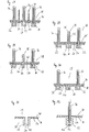
- FIGS. 15 to 21 undersides 20 of head regions 14 of further particularly preferred embodiments of the toothbrush 10 according to the invention are shown.
- a bristle carrier element 22 is arranged with a multiplicity of upper carrier element openings 26, which are indicated by dashed lines.
- all embodiments in the neck region-side head region 14 are equipped with conventional bristle holes 30.
- mutually different from each other with respect to the longitudinal axis of the head portion 14 middle regions of the head portion 14 are designed.
- the embodiments in the FIGS. 15, 16, 17, 18 and 20 each side outside bristle support elements 22, each with two support element openings 26 on the top 28 on.
- FIGS. 15, 16, 19 and 20 are also formed with bristle-carrying members 22 having two or more upper support member openings 26 in a central portion of the head portion 14.
- the embodiments in the FIGS. 15, 16 and 18 in the neck area side portion of the head portion 14 are provided with a constriction of the film-like hard film 24, by which the elasticity of the longitudinal end-side bristle support members 22 relative to the neck portion 12 is increased again.
- a constriction of the film-like hard film 24 by which the elasticity of the longitudinal end-side bristle support members 22 relative to the neck portion 12 is increased again.
- continuous, hole-like film recesses within the film-like hard film 24 serve, as the illustrated lateral constrictions, to increase the elasticity.
- the film recesses preferably have an elongated, slit-like shape and pass between the adjacent bristle carrier elements.
- the film recesses are preferably not filled with the following layer of soft material W.
- Fig. 21 In addition, the possibility is shown that the bristle carrier elements 22 are interconnected by minimal webs. As a result, the flexibility (direction and extent) of the brush head can be additionally determined.
- Fig. 26 In addition, cleaning and massage elements 18 are mounted on the underside 20 of the toothbrush 10. The design options for such elements are in the FIGS. 27 to 30 shown.
- FIGS. 44 and 45 Another embodiment of the inventive brush head is in FIGS. 44 and 45 shown.
- the bristle carrier elements 22 are on foil-like hard film 24 is attached.
- a material bridge 74 made of soft material W and / or hard material H is formed over the bristle carrier elements 22.
- the material bridge 74 has its points of attack (bridgeheads) in the free end region of the head region 14 and on the other hand in the transition from the film-like hard film 24 to the neck region 12 of the toothbrush 10. Structures can be formed on the material bridge 74 which can serve as tongue scrapers 44.
- the material bridge 74 serves to adjust the flexibility of the head region 14.
- the production of in Fig. 44 illustrated toothbrush 10 is preferably carried out with the cavity scooping side slides in the injection mold.
- the material bridge 74 can be formed in the same operation as the film-like hard film 24 and the bristle carrier elements 22 of the same material from the same injection point by injection molding.
- the film-like hard film 24 and the bristle carrier elements 22 can be formed in a first operation in a first injection molding process without a side slide and the material bridge 74 with a side slide.
- a material bridge 74 of soft material W made of the same material and in the same injection molding process as the layer of soft material W on the top 28 of the film-like hard film 24 are formed.
- other or existing materials can be processed in additional injection molding processes to create the desired material bridge 74. It is essential that the materials used are compatible with each other to allow a material connection during the injection molding process form.
- FIGS. 27 to 30 5 are sectional views of portions of the head region 14 in which cleaning or massage elements 18 are formed in different ways by a combination of hard and soft materials H, W.
- the layer of soft material W applied to the upper side 28 above the film-like hard film 24 is provided with rods or lamellar extensions which extend essentially perpendicular to the upper side 28 and parallel to the bristles 16.
- Fig. 28 shows a further embodiment in which these rods or lamellar cleaning or massage elements 18 by an inner structure 42 of a hard material H, which also rises like a rod or lamellar parallel to the bristles 16 in the direction of the top 28, are supported.
- a cleaning or massage element 18 for forming a tongue scraper element 44 is likewise arranged from a hard material H.
- a rod or lamellar cleaning or massage element 18 made of soft material W on the top 28 formed.
- the soft material W is also guided to the underside 20 and there forms a soft elastic tongue scraper element 44, however Fig. 30 shown embodiment, formed by a hard material H inner structure 42, which in the direction of the bottom 20 of the film-like hard film 44 protrudes, supported or stiffened.
- inner structures 42 may be formed of a hard material H both in the direction of the top 28, as well as in the direction of the bottom 20 to support a soft elastic structure.
- the bristles 16 can also be fastened in sleeve-shaped bristle carrier elements 22 by means of an AFT method or IMT method.
- Brush heads made using the IMT process largely correspond to the previous design variants.
- the bristles are first fed to injection molding. These are then encapsulated with plastic to form the brush head. The bristles are thus also inserted into the 'blind holes' formed by the bristles.
- FIG Fig. 31 A sleeve-shaped bristle carrier element 22 with sections of the adjacent film-like hard film 24 used in the AFT method is shown in FIG Fig. 31 shown. Opposite the upper support element opening 26, a lower support element opening 50 is formed through the through hole 48 on the underside 20.
- all considerations and Ausgestalltungstinen which concern the bristle carrier elements 22 with blind holes 36 analogous to bristle carrier elements 22 with through holes 48 transferable.
- Fig. 32 is the in Fig. 31 shown section after a bribe by AFT method shown.
- the bristles are pushed through the through holes of the bristle carrier elements 22. Subsequently, the back ends of the bristles are melted for anchoring.
- the bristles 16 are welded together to form a bundle of bristles in a welding section 52, and preferably also with the bristle carrier element 22 in the case of compatible materials.
- As a stock of material for the welding it is possible that within the through hole 48 in the region of the lower support member opening 50 projections are formed, which are attached as additional material for the welding.
- the welding takes place in the AFT process method by means of a hot stamp, which melts the bristle material.
- the cooled body or the weld section 52 often has brow or other weld edges, which pose a risk of injury.
- a lid made of plastic or other weldable material to the underside 20 of the bristle carrier element below the lower carrier element opening 50.
- the AFT or IMT process allows the formation of bristle bundles with almost any cross-sectional shapes. For example, elongated l- or C-shaped cross-sectional shapes of bristle bundles can be formed.
- These elongate bristle carrier elements 22 are preferably oriented along the longitudinal and / or transverse direction of the brush head. Examples of such shaped head portions 14 are in the FIGS. 33 to 36 shown.
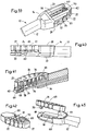
- a brush attachment 54 for an electrically operated toothbrush 10 shown in both the partially sectioned side view in Fig. 38 as well as the top view of the head area 14 in FIG Fig. 37 Shown are radially outward bristle carrier elements 22, which are connected via a film-like hard film 24 elastically connected to a central region of the head portion 14 is formed.
- the bristle carrier elements 22 can also accommodate cleaning or massage elements 18. Also in this embodiment, it is possible to form bristle carrier elements 22 with a plurality of upper carrier element openings 26.
- FIGS. 39 to 43 a further embodiment of a non-inventive toothbrush 10 is presented. Also in this embodiment is an electrically operated toothbrush.
- This has a not shown electric drive device which acts on the underside 20 of the bristle carrier elements 22 by means of an actuator, in this case by means of an eccentric 58 formed on a rotatable drive shaft 56.
- a head support 60 is provided with a slot recess 62, in which the drive shaft 56 is guided, and the head element 65 is equipped with an eccentric receiving element 70.
- an eccentric receptacle 68 is formed, in which the eccentric 58 engages and thereby acts on the special head element 65.
- the head carrier 60 has a head receptacle 64, in which the in Fig. 42 shown head element 65, which essentially corresponds to that in the embodiments previously shown by the head portion 14 is received.
- the head element 65 is fastened to the head support, for example, by means of welding (ultrasound or hot stamping), encapsulation with a further hard or soft material W, gluing, clamping or a mechanical anchorage, for example a snap connection or splined connection on the head support 60.
- the drive axle 56 is mounted in its free head area-side end region in a cylindrical axle receptacle 66 in the head carrier 60.
- the formed by a bend of the drive shaft 56 eccentric 58 engages in the eccentric receptacle 68 of the Exzenterinformationelements 70 a.
- the eccentric receiving element 70 itself is fastened to the underside 20 of a bristle carrier element 22, a plurality of bristle carrier elements 22 or directly to the film-like hard film 24.
- the drive shaft 56 is in rotation about its longitudinal axis added.
- the rotation is preferably 360 ° circumferential, but there are also reversing movements in a smaller angular range possible.
- the movement speed is preferably between 5,000 to 15,000 rpm, particularly preferably 8,000 to 12,000 rpm.
- the eccentric 58 also rotates with the drive shaft 56, periodically deflecting the eccentric receiving element 70 and the bristle carrier element 22 connected thereto, the bristle carrier elements 22 or the film-like hard film 24.
- both the directly associated with the Exzenteringelement 70 bristle carrier element 22, as well as adjacent bristle carrier elements 22, and the bristles 16 received by them is placed in a wave-like movement.
- the eccentric receptacle 68 of the eccentric receiving element 70 is preferably provided with an oval cross-section, which preferably has a larger diameter at least approximately parallel to the orientation of the bristles 16.
- the bristle carrier element 22 can also be driven to a kind of wiping movement.
- the shape of the eccentric receiver 68 and the eccentric 58 determine the moving image and the deflection amplitude of the bristle carrier element or hard film 24.
- An eccentric receiver 68 with a circular cross-section causes the movement to be both raising and lowering and wiping in both directions is equally removed from the drive shaft 56.
- An oval configuration of the shape of the eccentric receptacle 68 causes the movement of the eccentric 58 in the direction of the shorter axis of the oval cross section is transmitted more than in the direction of the longer axis of the oval cross section.
- the drive shaft 56 has a cross-sectional diameter of 0.5 mm to 2 mm, preferably 0.75 mm to 1.5 mm.
- the eccentric 58 is offset in the drive shaft with a deflection of 0.25 x to 1.25 x, preferably 0.5 x to 1 x the diameter of the drive shaft 56.
- the maximum deflection of the bristle field is transmitted 1: 1 from the eccentric 58.
- the bristle field moves in the vertical 0.05 mm to 1 mm, preferably 0.1 mm to 0.5 mm and in the horizontal 0.05 to 1.5 mm, preferably 0.1 to 1 mm.
- eccentric receptacle 68 it is possible to realize the eccentric receptacle 68 as a fork profile, while the profile is narrowed on the open side, so that the drive shaft 56 can be taken by means of this constriction.
- This embodiment entails that in a head element 65 various ways of massage and cleaning elements 18 can be achieved.
- further eccentric 58 may be formed, which can drive via corresponding further Exzenterability electrode 70 connected to them bristle carrier elements 22 to move.
- These eccentrics 58 are not necessarily uniform ie aligned in the same direction on the drive shaft 56.
- the slot recess 62 may be covered by additional elements to the bottom 20.
- header 65 and head carrier 60 may also be covered.
- a lateral wall which preferably extends to the open end of the head receptacle 64, can be realized by the head carrier 60.
- FIGS. 39 to 43 shown head portion 14 and subsequent neck portion 12 it is possible in the FIGS. 39 to 43 shown head portion 14 and subsequent neck portion 12 to make in the form of a brush attachment.
- the previously described arrangements for the drive shaft 56 and the eccentric receptacle 68 assume that these two elements in the assembled state, without retracted eccentric 58, are arranged centered on the drive shaft 56.
- the movement pattern of the cleaning and massage elements 18 on the head element 18 is determined by a variety of factors. Factors are: arrangement of the bristle carrier elements 22, shape of the bristle carrier elements 22, properties of the film-like hard film 24, attachment of the head element 65 in the head carrier 60, number of eccentric receiving elements 70, etc.
- the storage of the drive shaft 56 affects the device sustainable. An inaccurate storage entails that on the one hand, the noise caused by the friction and on the other hand that the friction losses require a larger engine power.
- it is also possible to fix a metallic carrier in the head carrier 60 for example by means of overmolding, mechanical assembly by means of press fit, or other suitable fixing method).
- the storage is designed so directly metallic and can be produced with a higher precision.
- the in the Fig. 39 to 43 illustrated embodiment relates to the head portion 14 of an electric toothbrush.
- the head design described can be mounted in various ways on a drive unit with energy storage of an electric toothbrush.
- the components can be molded integrally. This means that when the brush is worn out, the whole device needs to be replaced.
- the brush attachment 54 is configured such that when the brush part is attached to the drive unit, the drive shaft 56 of the brush attachment 54 is coupled together with the drive shaft of the drive unit.
- the structure of the header i. Head carrier 60, drive shaft 56 and head 65, allow a large variety of variants with minimal effort.
- the head element 65 can be designed differently. So can be bypassed without changing the other parts.
- the assembly of the multi-part head portion 14 takes place in several steps. First, the drive shaft 56 is inserted into the bristled head 65. Thereafter, this combination is assembled together in the head carrier 60, i. first, the drive shaft 56 is threaded, then the head member 65 is placed on the body, then the drive shaft 56 is inserted into the axle receiver 66 and finally the head member 65 is mounted on the head carrier 60, e.g. attached by ultrasonic welding or other suitable fixation method. Following these steps, the connection is made with the drive unit or with the transmission.
- toothbrushes 10 in particular its head region 14, can also be applied to electric toothbrushes with, for example, oscillating, pivoting or vibrating heads, to other bodycare brushes such as mascara brushes, nail polish brushes, hairbrushes and household brushes, for example and not conclusively on dishwashing brushes, Wischersets, shoe brushes, scrubbers, brooms or grill brushes are transferred.
- bristles 16 instead of bristles 16 also exclusively cleaning or massage elements 18 may be formed on the bristle carrier elements 22 and thereby form an example to be used exclusively as a tongue cleaner instrument.
- the most important prerequisite for the production of the toothbrush 10 according to the invention is the possibility of spraying or applying hard and soft material H, W in foil-like or film-like thin layers.
- hard material H particularly preferably polypropylene PP
- injection pressures in the injection molding tool of over 800 bar, preferably between 1000 and 1500 bar needed.
- polypropylene for toothbrushes with corresponding cross-sections is processed at an injection pressure of 500 bar to 750 bar.
- the temperature of the hard material H to be injected is between 220 ° C and 280 ° C, preferably between 235 ° C and 265 ° C.
- the said preferred injection pressures are several times what used for the production of conventional toothbrushes.
- the film-like hard film 24 has the desired film-like, flexible properties and at the same time the bristle-carrying elements 22 can be formed without sink marks in the required shape and size.
- the use of sliders and cores in the necessary to use injection molding tools For training specific curved tops 28, as well as obliquely to the top 28 extending blind holes 38 and through holes 48, where appropriate, the use of sliders and cores in the necessary to use injection molding tools.
Landscapes
- Brushes (AREA)
Claims (27)
- Brosse à dents avec une zone de poignée et avec une zone de cou (12) raccordée à la zone de poignée, qui supporte, à l'opposé de la zone de poignée, une zone de tête (14), qui présente au moins un élément de support de poils (22) pour la réception de poils (16), les poils (16) émergeant d'au moins un orifice supérieur (26) d'élément de support de l'élément de support de poils (22) vers une face supérieure (28) de la brosse à dents (10), l'élément de support de poils (22) étant connecté de façon apte à être dévié élastiquement par rapport à la zone de cou (12) et élastiquement à la zone de cou (12) au moyen d'un film dur de type feuille (24), formé en une pièce avec ledit élément de support de poils et fait d'un matériau dur (H), et le film dur de type feuille (24) s'étendant au moins par tronçons de façon affleurante à l'extérieur autour de l'orifice supérieur (26) d'élément de support, caractérisée en ce qu'une couche d'un autre matériau est appliquée sur le film dur de type feuille (24).
- Brosse à dents selon la revendication 1, caractérisée en ce que - mesurée entre la face supérieure (28) et une face inférieure opposée (20) - l'épaisseur du film dur de type feuille (24) est beaucoup plus petite que la longueur de l'élément de support de poils (22) et l'épaisseur du film dur de type feuille (24) est de 0,08 mm à 0,6 mm, préférablement de 0,3 mm à 0,5 mm.
- Brosse à dents selon la revendication 1 ou 2, caractérisée en ce que l'épaisseur de paroi de l'élément de support de poils (22) corresponde à un minimum de 1 à 2 fois, à un maximum de 4 à 8 fois, préférablement environ de 1 à 3 fois, l'épaisseur du film dur de type feuille (24).
- Brosse à dents selon l'une des revendications 1 à 3, caractérisée en ce que l'élément de support de poils (22) peut être élastiquement plié, en particulier à angle droit par rapport à la face supérieure (28), par rapport à un axe longitudinal et/ou à un axe transversal de la zone de tête (14) et/ou peut être tourné élastiquement autour d'un axe de la zone de tête (14).
- Brosse à dents selon l'une des revendications 1 à 4, caractérisée en ce que la brosse à dents (10) présente une multitude d'éléments de support de poils (22), qui sont connectés à la zone de cou (12) et le cas échéant l'un à l'autre au moyen du film dur de type feuille (24) et dont la déviation d'une position de repos non chargée est limitée chaque fois par un élément adjacent de support de poils (22) ou des éléments adjacents de support de poils (22), et l'angle de déviation maximum, mesuré entre la normale moyenne de l'orifice supérieur (26) le plus en avant d'élément de support dans l'état plat et la normale moyenne du premier orifice supérieur (26) d'élément de support dans l'état dévié, est de 30° à 75°, préférablement de 35° à 50°.
- Brosse à dents selon l'une des revendications 1 à 5, caractérisée en ce que l'élément de support de poils (22) est de type manchon.
- Brosse à dents selon la revendication 6, caractérisée en ce que les poils, dans leur région d'extrémité située du côté de l'élément de support, à un orifice inférieur (50), opposé à la face supérieure (28), d'élément de support de l'élément de support de poils (22), sont fondus les uns avec les autres.
- Brosse à dents selon l'une des revendications 1 à 5, caractérisée en ce que l'élément de support de poils (22) est formé en forme de gobelet avec un fond et ce faisant forme un trou borgne (36) dans lequel les poils (16) sont fixés au moyen d'ancres.
- Brosse à dents selon l'une des revendications 1 à 8, caractérisée en ce que l'élément de support de poils (22) et préférablement aussi le film dur de type feuille (24) sont façonnés de façon exposée au moins par tronçons vers la face inférieure (20) opposée à la face supérieure (28).
- Brosse à dents selon la revendication 9, caractérisée en ce que des bords, respectivement des éléments ou des structures récurrents, tels que protubérances, écailles et/ou un réseau, sont façonnés sur la face inférieure (20) de l'élément de support de poils (22) pour former un gratte-langue.
- Brosse à dents selon l'une des revendications 1 à 10, caractérisée en ce que l'élément de support de poils (22) et le film dur de type feuille (24) sont fabriqués d'un seul matériau dur (H).
- Brosse à dents selon l'une des revendications 1 à 11, caractérisée en ce que le matériau dur (H) est un plastique pas enclin à des ruptures fragiles, tels que polypropylène (PP), polyester (PET), polycyclohexane diméthanol téréphtalate (PCT/PCT-A (modifié en acide)/PCT-G (modifié en glycol)), polyéthylène (PE), polyméthylméthacrylate (PMMA), polyoxyméthylène (POM) ou polyamide (PA), préférablement polypropylène (PP), et, en plus de l'élément de support de poils (22) et du film dur de type feuille (24), d'autres parties de la brosse à dents (10) consistant en matériau dur sont fabriqués par moulage par injection au moyen préférablement d'un unique point de moulage par injection.
- Brosse à dents selon l'une des revendications 1 à 12, caractérisée en ce que la couche faite d'un autre matériau sur le film dur de type feuille (24) est faite d'un matériau mou (W) produit à partir de plastique et est appliquée préférablement sur la face supérieure (28).
- Brosse à dents selon la revendication 13, caractérisée en ce que le matériau mou (W) est un plastique, tel que polyéthylène basse densité (PE-LD), polyéthylène haute densité (PE-HD), polyéthylène (PE), chlorure de polyvinyle (PVC), polyuréthane (PUR) ou un élastomère thermoplastique (TPE), préférablement un élastomère thermoplastique (TPE), avec une dureté Shore A inférieure à 90, préférablement inférieure à 70.
- Brosse à dents selon la revendication 13 ou 14, caractérisée en ce que l'épaisseur de couche du matériau mou (W) est entre 0,2 mm et 1 mm, préférablement entre 0,3 mm et 0,7 mm.
- Brosse à dents selon l'une des revendications 13 à 15, caractérisée en ce que l'épaisseur totale du film dur de type feuille (24) fait du matériau dur (H) et de la couche faite de matériau mou (W) est entre 0,28 mm et 1,3 mm, préférablement entre 0,6 mm et 1,2 mm.
- Brosse à dents selon l'une des revendications 13 à 16, caractérisée en ce que le rapport de l'épaisseur de couche du film dur de type feuille (24) avec l'épaisseur de couche du matériau mou (W) situé dessus est de 12,5 : 1 à 0,8 : 1, préférablement de 7 : 1 à 1,5 : 1.
- Brosse à dents selon l'une des revendications 13 à 17, caractérisée en ce que le matériau mou (W) sur l'élément de support de poils (22) forme sur la face supérieure (28) et/ou sur la face inférieure opposée (20) un bourrelet (38) qui, le cas échéant, est agrandi dans la direction longitudinale des poils (16).
- Brosse à dents selon l'une des revendications 1 à 18, caractérisée en ce que l'élément de support de poils (22) présente deux à dix-huit, préférablement deux à sept ou douze à dix-huit orifices supérieurs (26) d'élément de support.
- Brosse à dents selon l'une des revendications 1 à 19, caractérisée en ce que des éléments (18) élastiques caoutchouteux de nettoyage et/ou de massage sont disposés sur l'élément de support de poils (22).
- Brosse à dents selon la revendications 13 et 20, caractérisée en ce que la couche de matériau mou (W) et les éléments (18) élastiques caoutchouteux de nettoyage et/ou de massage (18) sont fabriqués avec le même matériau et à partir du même point de moulage par injection.
- Brosse à dents selon l'une des revendications 1 à 21, caractérisée en ce que la face supérieure (28) de la zone de tête (14) présente un ou plusieurs arrondis, préférablement - vu de la face supérieure (28) - un arrondi concave.
- Brosse à dents selon l'une des revendications 1 à 22, caractérisée en ce que l'épaisseur et le matériau du film dur de type feuille (24) sont sélectionnés de telle façon que, sous l'effet d'une force de 5N agissant dans la direction longitudinale des poils (16), l'élément de support de poils (22) est plié de 5 mm à 10 mm, préférablement d'environ 7 mm, dans la direction de la force agissante par rapport à sa position de repos déchargée.
- Brosse à dents selon l'une des revendications 1 à 23, caractérisée en ce que des lignes de pliage formées dans le film dur de type feuille (24) s'étendent rectilignement seulement sur un tronçon intérieur de la zone de tête (14) et sont pliées ou se ramifient vers des tronçons de bord extérieurs de ladite zone de tête.
- Brosse à dents selon l'une des revendications 1 à 24, caractérisée en ce qu'un pont de matière (74) s'étendant au-delà d'éléments de support de poils (22) est façonné sur la face inférieure (20) de la zone de tête (12).
- Brosse à dents selon l'une des revendications 1 à 25, caractérisée en ce que la brosse à dents (10) est munie d'un dispositif électrique d'entraînement, au moyen duquel un actuateur, préférablement un excentrique (58), peut être entraîné qui agit sur l'élément de support de poils (22), préférablement sur sa face inférieure opposée aux poils (20), et qui dévie ledit élément de support de poils (22) pour soutenir l'action de nettoyage.
- Méthode pour la fabrication d'une brosse à dents selon l'une des revendications 1 à 26, caractérisée en ce que, lors de la fabrication de la brosse à dents (10), une pression de moulage par injection de plus de 800 bar, préférablement entre 1000 bar et 1500 bar, règne dans une cavité d'un moule de moulage par injection pour former la brosse à dents (10).
Priority Applications (1)
| Application Number | Priority Date | Filing Date | Title |
|---|---|---|---|
| EP08715725.1A EP2114196B1 (fr) | 2007-02-14 | 2008-02-11 | Brosse à dents |
Applications Claiming Priority (3)
| Application Number | Priority Date | Filing Date | Title |
|---|---|---|---|
| EP07003109A EP1958534A1 (fr) | 2007-02-14 | 2007-02-14 | Brosse à dents |
| PCT/EP2008/001013 WO2008098721A1 (fr) | 2007-02-14 | 2008-02-11 | Brosse à dents |
| EP08715725.1A EP2114196B1 (fr) | 2007-02-14 | 2008-02-11 | Brosse à dents |
Publications (2)
| Publication Number | Publication Date |
|---|---|
| EP2114196A1 EP2114196A1 (fr) | 2009-11-11 |
| EP2114196B1 true EP2114196B1 (fr) | 2017-03-15 |
Family
ID=38229996
Family Applications (2)
| Application Number | Title | Priority Date | Filing Date |
|---|---|---|---|
| EP07003109A Withdrawn EP1958534A1 (fr) | 2007-02-14 | 2007-02-14 | Brosse à dents |
| EP08715725.1A Not-in-force EP2114196B1 (fr) | 2007-02-14 | 2008-02-11 | Brosse à dents |
Family Applications Before (1)
| Application Number | Title | Priority Date | Filing Date |
|---|---|---|---|
| EP07003109A Withdrawn EP1958534A1 (fr) | 2007-02-14 | 2007-02-14 | Brosse à dents |
Country Status (3)
| Country | Link |
|---|---|
| US (1) | US20100088836A1 (fr) |
| EP (2) | EP1958534A1 (fr) |
| WO (1) | WO2008098721A1 (fr) |
Families Citing this family (32)
| Publication number | Priority date | Publication date | Assignee | Title |
|---|---|---|---|---|
| US8434190B2 (en) * | 2008-09-01 | 2013-05-07 | Braun Gmbh | Toothbrush and method of manufacturing it |
| USD657569S1 (en) * | 2010-02-26 | 2012-04-17 | Colgate-Palmolive Company | Head portion of an oral care implement |
| KR101548839B1 (ko) * | 2010-12-21 | 2015-08-31 | 콜게이트-파아므올리브캄파니 | 구강 관리 기구 |
| USD640059S1 (en) * | 2011-02-10 | 2011-06-21 | Ranir, Llc | Portion of a toothbrush |
| WO2013133848A1 (fr) * | 2012-03-09 | 2013-09-12 | Colgate-Palmolive Company | Procédé de formation d'une plaque de tête et formation d'instrument de soins dentaires l'utilisant |
| USD724324S1 (en) * | 2012-06-20 | 2015-03-17 | Braun Gmbh | Toothbrush head with tongue cleaner |
| AU2012397294B2 (en) * | 2012-12-20 | 2016-01-07 | Colgate-Palmolive Company | Oral care implement |
| JP2016501615A (ja) * | 2012-12-20 | 2016-01-21 | コルゲート・パーモリブ・カンパニーColgate−Palmolive Company | 口腔ケア器具を製造する方法 |
| EP3995036B1 (fr) | 2014-12-23 | 2025-06-04 | Colgate-Palmolive Company | Ustensile de soin buccal |
| BR112017010792B1 (pt) | 2014-12-23 | 2021-10-05 | Colgate-Palmolive Company | Instrumento de higiene bucal |
| MX393731B (es) | 2014-12-23 | 2025-03-24 | Colgate Palmolive Co | Implemento para el cuidado bucal. |
| US11291293B2 (en) | 2014-12-23 | 2022-04-05 | Colgate-Palmolive Company | Oral care implement |
| US10455931B2 (en) | 2014-12-23 | 2019-10-29 | Colgate-Palmolive Company | Oral care implement |
| EP3223657B1 (fr) | 2014-12-23 | 2022-12-07 | Colgate-Palmolive Company | Accessoire de soins buccaux |
| CA2970634C (fr) | 2014-12-23 | 2022-04-12 | Colgate-Palmolive Company | Ustensile pour l'hygiene bucco-dentaire comportant un manche a elements multiples |
| EP3223655B1 (fr) | 2014-12-23 | 2024-10-09 | Colgate-Palmolive Company | Instrument de soin buccal |
| WO2016105374A1 (fr) | 2014-12-23 | 2016-06-30 | Colgate-Palmolive Company | Instrument de soin buccal |
| US10660430B2 (en) | 2014-12-23 | 2020-05-26 | Colgate-Palmolive Company | Oral care implement having multi-component handle |
| RU2664278C1 (ru) | 2014-12-23 | 2018-08-15 | Колгейт-Палмолив Компани | Устройство для ухода за полостью рта, содержащее многокомпонентную ручку |
| USD780457S1 (en) | 2014-12-23 | 2017-03-07 | Colgate-Palmolive Company | Oral care implement |
| DE102016107759B4 (de) * | 2015-07-13 | 2024-11-14 | Gb Boucherie Nv | Verfahren und Vorrichtung zum Herstellen einer Bürste |
| EP3165126B1 (fr) * | 2015-11-09 | 2022-01-05 | M+C Schiffer GmbH | Tete de brosse pour une brosse a dents electrique |
| US11553780B2 (en) * | 2017-07-12 | 2023-01-17 | Koninklijke Philips N.V. | Brush head manufacturing method |
| RU2770726C2 (ru) | 2017-10-24 | 2022-04-21 | Конинклейке Филипс Н.В. | Способ изготовления головки щетки с использованием формованного держателя пучков и опорной пластины, а также головка щетки |
| US10548392B2 (en) | 2017-11-18 | 2020-02-04 | Tifinity Oral Care, Llc | Toothbrush with bristle-mounting system for retarding bristle strain |
| US10709533B2 (en) | 2017-12-12 | 2020-07-14 | Colgate-Palmolive Company | Oral care implement and handle and refill head thereof |
| US10631964B2 (en) | 2017-12-12 | 2020-04-28 | Colgate-Palmolive Company | Oral care implement |
| USD846883S1 (en) | 2017-12-12 | 2019-04-30 | Colgate-Palmolive Company | Handle of an oral care implement |
| JP7170958B2 (ja) * | 2018-08-06 | 2022-11-15 | 合資会社三和歯ブラシ工業所 | 歯ブラシ用基台及び歯ブラシ用基台を備えた歯ブラシ |
| USD891784S1 (en) | 2018-12-18 | 2020-08-04 | Colgate-Palmolive Company | Electric toothbrush handle |
| EP3934479A4 (fr) * | 2019-03-06 | 2022-10-05 | Tifinity Oral Care, LLC | Brosse à dents dotée d'un système de montage de poils pour retarder la déformation des poils |
| USD960582S1 (en) | 2020-12-10 | 2022-08-16 | Colgate-Palmolive Company | Oral care refill head |
Family Cites Families (25)
| Publication number | Priority date | Publication date | Assignee | Title |
|---|---|---|---|---|
| US1770195A (en) * | 1929-01-05 | 1930-07-08 | Gilderoy O Burlew | Toothbrush |
| US2254365A (en) * | 1939-06-06 | 1941-09-02 | Edward E Griffith | Convertible toothbrush |
| US2685703A (en) * | 1949-04-27 | 1954-08-10 | Edward F Dellenbach | Toothbrush |
| US2935755A (en) * | 1955-10-14 | 1960-05-10 | Leira Alberto Ramon | Tooth-brushes and the like |
| US3000030A (en) * | 1958-06-13 | 1961-09-19 | Du Pont | Brush |
| US3082457A (en) * | 1961-05-26 | 1963-03-26 | Florio R Lucibello | Self-adapting tufts for brushes |
| US3188672A (en) * | 1963-12-18 | 1965-06-15 | Johnson & Johnson | Brush |
| US4277862A (en) * | 1979-01-25 | 1981-07-14 | Alexander E. Vowles | Toothbrush |
| US5360026A (en) * | 1986-12-04 | 1994-11-01 | Oral Logic, Inc. | Tooth cleaning device and method |
| KR960016152B1 (ko) * | 1988-12-13 | 1996-12-04 | 롤프바만 | 칫솔의 제조방법 |
| US5318352A (en) * | 1990-11-20 | 1994-06-07 | Oraline International B.V. | Method of making a toothbrush |
| GB9106511D0 (en) * | 1991-03-27 | 1991-05-15 | Lingner & Fischer Gmbh | Novel article |
| GB9211338D0 (en) * | 1992-05-28 | 1992-07-15 | Ausworld Consultants Limited | Toothbrush |
| DE19538569A1 (de) * | 1995-10-17 | 1997-04-24 | Coronet Werke Gmbh | Borstenware mit verstellbarer Borstenhärte |
| TW384214B (en) * | 1995-12-29 | 2000-03-11 | Colgate Palmolive Co | Contouring toothbrush head |
| DE59603890D1 (de) * | 1996-06-27 | 2000-01-13 | Schiffer Fa M & C | Bürste und verfahren zu deren herstellung |
| JP2000516507A (ja) * | 1996-08-22 | 2000-12-12 | スミスクライン・ビーチャム・コンシューマー・ヘルスケア・ゲゼルシャフト・ミット・ベシュレンクテル・ハフツング | 歯ブラシ |
| CH692098A5 (de) * | 1997-12-30 | 2002-02-15 | Trisa Buerstenfabrik Ag | Drehbeweglich antreibbarer Bürstenkopf für eine motorisch betriebene Zahnbürste, insbesondere eine Elektrozahnbürste. |
| DE19816098A1 (de) * | 1998-04-09 | 1999-10-14 | Coronet Werke Gmbh | Reinigungsbürste, insbesondere Zahnbürste |
| JP2002051838A (ja) * | 2000-08-09 | 2002-02-19 | Lion Corp | 歯ブラシ |
| KR200274251Y1 (ko) * | 2002-01-28 | 2002-05-06 | 박효문 | 치모부가 전개되는 위생 칫솔 |
| DE10212701B4 (de) * | 2002-03-21 | 2015-05-13 | Geka Gmbh | Borste, Verfahren und Vorrichtung zu ihrer Herstellung sowie Borstenware |
| DE10221786A1 (de) * | 2002-05-15 | 2003-11-27 | Schiffer Fa M & C | Bürste und Verfahren zu deren Herstellung |
| DE10303548B4 (de) * | 2003-01-29 | 2016-10-20 | M + C Schiffer Gmbh | Bürste und Verfahren zu deren Herstellung |
| BRPI0514025A (pt) * | 2004-08-03 | 2008-05-27 | Unilever Nv | escova de dentes e método para fabricar uma escova de dentes |
-
2007
- 2007-02-14 EP EP07003109A patent/EP1958534A1/fr not_active Withdrawn
-
2008
- 2008-02-11 US US12/449,343 patent/US20100088836A1/en not_active Abandoned
- 2008-02-11 EP EP08715725.1A patent/EP2114196B1/fr not_active Not-in-force
- 2008-02-11 WO PCT/EP2008/001013 patent/WO2008098721A1/fr not_active Ceased
Non-Patent Citations (1)
| Title |
|---|
| None * |
Also Published As
| Publication number | Publication date |
|---|---|
| US20100088836A1 (en) | 2010-04-15 |
| EP1958534A1 (fr) | 2008-08-20 |
| WO2008098721A1 (fr) | 2008-08-21 |
| EP2114196A1 (fr) | 2009-11-11 |
Similar Documents
| Publication | Publication Date | Title |
|---|---|---|
| EP2114196B1 (fr) | Brosse à dents | |
| EP0888072B1 (fr) | Brosses et leur procede de fabrication | |
| EP1661487B2 (fr) | Brosse à dents et son procédé de fabrication | |
| EP3973920B1 (fr) | Brosse électrique de soins corporels | |
| EP3445205B1 (fr) | Produit de type brosse | |
| EP2298126B1 (fr) | Brosse à dent et son procédé de production | |
| DE69735595T2 (de) | Zahnbürste | |
| WO2006012938A2 (fr) | Brosse a dents presentant des evidements | |
| DE69810911T2 (de) | Zahnbürste | |
| DE69812097T2 (de) | Zahnbürste mit rippen | |
| EP3729997B1 (fr) | Procede de fabrication d'une brosse interdentaire | |
| DE69635847T2 (de) | Zahnbürste | |
| EP1282373B1 (fr) | Tete de brosse a dents | |
| DE10331369B4 (de) | Zahnbürste | |
| DE69736901T2 (de) | Zahnbürste mit einem elastomergefüllten federnden kopfteil | |
| EP1905382A1 (fr) | Brosse à dents électrique et transmission pour une brosse à dents électrique | |
| DE212005000010U1 (de) | Zahnbürste | |
| EP3160296A1 (fr) | Brosse à dents comportant des éléments mobiles | |
| EP1494561B1 (fr) | Brosse a dents et procede de fabrication | |
| DE69736902T2 (de) | Bürstenkopf | |
| EP1486137B1 (fr) | Brosse , notamment brosse à dents et son procédé de fabrication | |
| DE10221786A1 (de) | Bürste und Verfahren zu deren Herstellung | |
| EP1903906B1 (fr) | Tete de brosse a dents | |
| DE60011766T2 (de) | Zahnbürste mit gesteuerter kopfbewegung |
Legal Events
| Date | Code | Title | Description |
|---|---|---|---|
| PUAI | Public reference made under article 153(3) epc to a published international application that has entered the european phase |
Free format text: ORIGINAL CODE: 0009012 |
|
| 17P | Request for examination filed |
Effective date: 20090805 |
|
| AK | Designated contracting states |
Kind code of ref document: A1 Designated state(s): AT BE BG CH CY CZ DE DK EE ES FI FR GB GR HR HU IE IS IT LI LT LU LV MC MT NL NO PL PT RO SE SI SK TR |
|
| DAX | Request for extension of the european patent (deleted) | ||
| 17Q | First examination report despatched |
Effective date: 20130405 |
|
| GRAP | Despatch of communication of intention to grant a patent |
Free format text: ORIGINAL CODE: EPIDOSNIGR1 |
|
| INTG | Intention to grant announced |
Effective date: 20161006 |
|
| RIN1 | Information on inventor provided before grant (corrected) |
Inventor name: PFENNIGER, ADRIAN Inventor name: FISCHER, FRANZ Inventor name: LOETSCHER, JOSEF Inventor name: KIRCHHOFER, ROGER Inventor name: ZURFLUH, PETER |
|
| STAA | Information on the status of an ep patent application or granted ep patent |
Free format text: STATUS: GRANT OF PATENT IS INTENDED |
|
| GRAS | Grant fee paid |
Free format text: ORIGINAL CODE: EPIDOSNIGR3 |
|
| GRAA | (expected) grant |
Free format text: ORIGINAL CODE: 0009210 |
|
| STAA | Information on the status of an ep patent application or granted ep patent |
Free format text: STATUS: THE PATENT HAS BEEN GRANTED |
|
| AK | Designated contracting states |
Kind code of ref document: B1 Designated state(s): AT BE BG CH CY CZ DE DK EE ES FI FR GB GR HR HU IE IS IT LI LT LU LV MC MT NL NO PL PT RO SE SI SK TR |
|
| REG | Reference to a national code |
Ref country code: CH Ref legal event code: EP Ref country code: GB Ref legal event code: FG4D Free format text: NOT ENGLISH Ref country code: CH Ref legal event code: NV Representative=s name: PATENTANWAELTE SCHAAD, BALASS, MENZL AND PARTN, CH |
|
| REG | Reference to a national code |
Ref country code: IE Ref legal event code: FG4D Free format text: LANGUAGE OF EP DOCUMENT: GERMAN |
|
| REG | Reference to a national code |
Ref country code: AT Ref legal event code: REF Ref document number: 874680 Country of ref document: AT Kind code of ref document: T Effective date: 20170415 |
|
| REG | Reference to a national code |
Ref country code: DE Ref legal event code: R096 Ref document number: 502008015124 Country of ref document: DE |
|
| REG | Reference to a national code |
Ref country code: NL Ref legal event code: MP Effective date: 20170315 |
|
| REG | Reference to a national code |
Ref country code: LT Ref legal event code: MG4D |
|
| PG25 | Lapsed in a contracting state [announced via postgrant information from national office to epo] |
Ref country code: HR Free format text: LAPSE BECAUSE OF FAILURE TO SUBMIT A TRANSLATION OF THE DESCRIPTION OR TO PAY THE FEE WITHIN THE PRESCRIBED TIME-LIMIT Effective date: 20170315 Ref country code: FI Free format text: LAPSE BECAUSE OF FAILURE TO SUBMIT A TRANSLATION OF THE DESCRIPTION OR TO PAY THE FEE WITHIN THE PRESCRIBED TIME-LIMIT Effective date: 20170315 Ref country code: LT Free format text: LAPSE BECAUSE OF FAILURE TO SUBMIT A TRANSLATION OF THE DESCRIPTION OR TO PAY THE FEE WITHIN THE PRESCRIBED TIME-LIMIT Effective date: 20170315 Ref country code: GR Free format text: LAPSE BECAUSE OF FAILURE TO SUBMIT A TRANSLATION OF THE DESCRIPTION OR TO PAY THE FEE WITHIN THE PRESCRIBED TIME-LIMIT Effective date: 20170616 Ref country code: NO Free format text: LAPSE BECAUSE OF FAILURE TO SUBMIT A TRANSLATION OF THE DESCRIPTION OR TO PAY THE FEE WITHIN THE PRESCRIBED TIME-LIMIT Effective date: 20170615 |
|
| PG25 | Lapsed in a contracting state [announced via postgrant information from national office to epo] |
Ref country code: SE Free format text: LAPSE BECAUSE OF FAILURE TO SUBMIT A TRANSLATION OF THE DESCRIPTION OR TO PAY THE FEE WITHIN THE PRESCRIBED TIME-LIMIT Effective date: 20170315 Ref country code: LV Free format text: LAPSE BECAUSE OF FAILURE TO SUBMIT A TRANSLATION OF THE DESCRIPTION OR TO PAY THE FEE WITHIN THE PRESCRIBED TIME-LIMIT Effective date: 20170315 Ref country code: BG Free format text: LAPSE BECAUSE OF FAILURE TO SUBMIT A TRANSLATION OF THE DESCRIPTION OR TO PAY THE FEE WITHIN THE PRESCRIBED TIME-LIMIT Effective date: 20170615 |
|
| PG25 | Lapsed in a contracting state [announced via postgrant information from national office to epo] |
Ref country code: NL Free format text: LAPSE BECAUSE OF FAILURE TO SUBMIT A TRANSLATION OF THE DESCRIPTION OR TO PAY THE FEE WITHIN THE PRESCRIBED TIME-LIMIT Effective date: 20170315 |
|
| PG25 | Lapsed in a contracting state [announced via postgrant information from national office to epo] |
Ref country code: RO Free format text: LAPSE BECAUSE OF FAILURE TO SUBMIT A TRANSLATION OF THE DESCRIPTION OR TO PAY THE FEE WITHIN THE PRESCRIBED TIME-LIMIT Effective date: 20170315 Ref country code: CZ Free format text: LAPSE BECAUSE OF FAILURE TO SUBMIT A TRANSLATION OF THE DESCRIPTION OR TO PAY THE FEE WITHIN THE PRESCRIBED TIME-LIMIT Effective date: 20170315 Ref country code: ES Free format text: LAPSE BECAUSE OF FAILURE TO SUBMIT A TRANSLATION OF THE DESCRIPTION OR TO PAY THE FEE WITHIN THE PRESCRIBED TIME-LIMIT Effective date: 20170315 Ref country code: EE Free format text: LAPSE BECAUSE OF FAILURE TO SUBMIT A TRANSLATION OF THE DESCRIPTION OR TO PAY THE FEE WITHIN THE PRESCRIBED TIME-LIMIT Effective date: 20170315 Ref country code: SK Free format text: LAPSE BECAUSE OF FAILURE TO SUBMIT A TRANSLATION OF THE DESCRIPTION OR TO PAY THE FEE WITHIN THE PRESCRIBED TIME-LIMIT Effective date: 20170315 |
|
| PG25 | Lapsed in a contracting state [announced via postgrant information from national office to epo] |
Ref country code: PL Free format text: LAPSE BECAUSE OF FAILURE TO SUBMIT A TRANSLATION OF THE DESCRIPTION OR TO PAY THE FEE WITHIN THE PRESCRIBED TIME-LIMIT Effective date: 20170315 Ref country code: IS Free format text: LAPSE BECAUSE OF FAILURE TO SUBMIT A TRANSLATION OF THE DESCRIPTION OR TO PAY THE FEE WITHIN THE PRESCRIBED TIME-LIMIT Effective date: 20170715 Ref country code: PT Free format text: LAPSE BECAUSE OF FAILURE TO SUBMIT A TRANSLATION OF THE DESCRIPTION OR TO PAY THE FEE WITHIN THE PRESCRIBED TIME-LIMIT Effective date: 20170717 |
|
| REG | Reference to a national code |
Ref country code: DE Ref legal event code: R097 Ref document number: 502008015124 Country of ref document: DE |
|
| PLBE | No opposition filed within time limit |
Free format text: ORIGINAL CODE: 0009261 |
|
| STAA | Information on the status of an ep patent application or granted ep patent |
Free format text: STATUS: NO OPPOSITION FILED WITHIN TIME LIMIT |
|
| PG25 | Lapsed in a contracting state [announced via postgrant information from national office to epo] |
Ref country code: DK Free format text: LAPSE BECAUSE OF FAILURE TO SUBMIT A TRANSLATION OF THE DESCRIPTION OR TO PAY THE FEE WITHIN THE PRESCRIBED TIME-LIMIT Effective date: 20170315 |
|
| 26N | No opposition filed |
Effective date: 20171218 |
|
| REG | Reference to a national code |
Ref country code: FR Ref legal event code: PLFP Year of fee payment: 11 |
|
| PG25 | Lapsed in a contracting state [announced via postgrant information from national office to epo] |
Ref country code: SI Free format text: LAPSE BECAUSE OF FAILURE TO SUBMIT A TRANSLATION OF THE DESCRIPTION OR TO PAY THE FEE WITHIN THE PRESCRIBED TIME-LIMIT Effective date: 20170315 Ref country code: IT Free format text: LAPSE BECAUSE OF FAILURE TO SUBMIT A TRANSLATION OF THE DESCRIPTION OR TO PAY THE FEE WITHIN THE PRESCRIBED TIME-LIMIT Effective date: 20170315 |
|
| PGFP | Annual fee paid to national office [announced via postgrant information from national office to epo] |
Ref country code: GB Payment date: 20180216 Year of fee payment: 11 |
|
| PGFP | Annual fee paid to national office [announced via postgrant information from national office to epo] |
Ref country code: FR Payment date: 20180223 Year of fee payment: 11 |
|
| PG25 | Lapsed in a contracting state [announced via postgrant information from national office to epo] |
Ref country code: MT Free format text: LAPSE BECAUSE OF FAILURE TO SUBMIT A TRANSLATION OF THE DESCRIPTION OR TO PAY THE FEE WITHIN THE PRESCRIBED TIME-LIMIT Effective date: 20170315 Ref country code: MC Free format text: LAPSE BECAUSE OF FAILURE TO SUBMIT A TRANSLATION OF THE DESCRIPTION OR TO PAY THE FEE WITHIN THE PRESCRIBED TIME-LIMIT Effective date: 20170315 |
|
| REG | Reference to a national code |
Ref country code: IE Ref legal event code: MM4A |
|
| REG | Reference to a national code |
Ref country code: BE Ref legal event code: MM Effective date: 20180228 |
|
| PG25 | Lapsed in a contracting state [announced via postgrant information from national office to epo] |
Ref country code: LU Free format text: LAPSE BECAUSE OF NON-PAYMENT OF DUE FEES Effective date: 20180211 |
|
| PG25 | Lapsed in a contracting state [announced via postgrant information from national office to epo] |
Ref country code: IE Free format text: LAPSE BECAUSE OF NON-PAYMENT OF DUE FEES Effective date: 20180211 |
|
| PG25 | Lapsed in a contracting state [announced via postgrant information from national office to epo] |
Ref country code: BE Free format text: LAPSE BECAUSE OF NON-PAYMENT OF DUE FEES Effective date: 20180228 |
|
| REG | Reference to a national code |
Ref country code: AT Ref legal event code: MM01 Ref document number: 874680 Country of ref document: AT Kind code of ref document: T Effective date: 20180211 |
|
| PG25 | Lapsed in a contracting state [announced via postgrant information from national office to epo] |
Ref country code: AT Free format text: LAPSE BECAUSE OF NON-PAYMENT OF DUE FEES Effective date: 20180211 |
|
| PGFP | Annual fee paid to national office [announced via postgrant information from national office to epo] |
Ref country code: CH Payment date: 20190218 Year of fee payment: 12 Ref country code: DE Payment date: 20190219 Year of fee payment: 12 |
|
| GBPC | Gb: european patent ceased through non-payment of renewal fee |
Effective date: 20190211 |
|
| PG25 | Lapsed in a contracting state [announced via postgrant information from national office to epo] |
Ref country code: GB Free format text: LAPSE BECAUSE OF NON-PAYMENT OF DUE FEES Effective date: 20190211 |
|
| PG25 | Lapsed in a contracting state [announced via postgrant information from national office to epo] |
Ref country code: FR Free format text: LAPSE BECAUSE OF NON-PAYMENT OF DUE FEES Effective date: 20190228 |
|
| PG25 | Lapsed in a contracting state [announced via postgrant information from national office to epo] |
Ref country code: TR Free format text: LAPSE BECAUSE OF FAILURE TO SUBMIT A TRANSLATION OF THE DESCRIPTION OR TO PAY THE FEE WITHIN THE PRESCRIBED TIME-LIMIT Effective date: 20170315 |
|
| PG25 | Lapsed in a contracting state [announced via postgrant information from national office to epo] |
Ref country code: HU Free format text: LAPSE BECAUSE OF FAILURE TO SUBMIT A TRANSLATION OF THE DESCRIPTION OR TO PAY THE FEE WITHIN THE PRESCRIBED TIME-LIMIT; INVALID AB INITIO Effective date: 20080211 |
|
| PG25 | Lapsed in a contracting state [announced via postgrant information from national office to epo] |
Ref country code: CY Free format text: LAPSE BECAUSE OF FAILURE TO SUBMIT A TRANSLATION OF THE DESCRIPTION OR TO PAY THE FEE WITHIN THE PRESCRIBED TIME-LIMIT Effective date: 20170315 |
|
| REG | Reference to a national code |
Ref country code: DE Ref legal event code: R119 Ref document number: 502008015124 Country of ref document: DE |
|
| REG | Reference to a national code |
Ref country code: CH Ref legal event code: PL |
|
| PG25 | Lapsed in a contracting state [announced via postgrant information from national office to epo] |
Ref country code: LI Free format text: LAPSE BECAUSE OF NON-PAYMENT OF DUE FEES Effective date: 20200229 Ref country code: CH Free format text: LAPSE BECAUSE OF NON-PAYMENT OF DUE FEES Effective date: 20200229 |
|
| PG25 | Lapsed in a contracting state [announced via postgrant information from national office to epo] |
Ref country code: DE Free format text: LAPSE BECAUSE OF NON-PAYMENT OF DUE FEES Effective date: 20200901 |