EP1621361A2 - Dispositif de transport pour blocs de livres - Google Patents
Dispositif de transport pour blocs de livres Download PDFInfo
- Publication number
- EP1621361A2 EP1621361A2 EP05106074A EP05106074A EP1621361A2 EP 1621361 A2 EP1621361 A2 EP 1621361A2 EP 05106074 A EP05106074 A EP 05106074A EP 05106074 A EP05106074 A EP 05106074A EP 1621361 A2 EP1621361 A2 EP 1621361A2
- Authority
- EP
- European Patent Office
- Prior art keywords
- transport
- compartments
- cooling device
- book blocks
- book
- Prior art date
- Legal status (The legal status is an assumption and is not a legal conclusion. Google has not performed a legal analysis and makes no representation as to the accuracy of the status listed.)
- Withdrawn
Links
Images



Classifications
-
- B—PERFORMING OPERATIONS; TRANSPORTING
- B42—BOOKBINDING; ALBUMS; FILES; SPECIAL PRINTED MATTER
- B42C—BOOKBINDING
- B42C13/00—Bookbinding presses; Joint-creasing equipment for bookbinding; Drying or setting devices for books
- B42C13/006—Drying or setting devices for books
-
- B—PERFORMING OPERATIONS; TRANSPORTING
- B42—BOOKBINDING; ALBUMS; FILES; SPECIAL PRINTED MATTER
- B42C—BOOKBINDING
- B42C19/00—Multi-step processes for making books
- B42C19/08—Conveying between operating stations in machines
-
- B—PERFORMING OPERATIONS; TRANSPORTING
- B65—CONVEYING; PACKING; STORING; HANDLING THIN OR FILAMENTARY MATERIAL
- B65G—TRANSPORT OR STORAGE DEVICES, e.g. CONVEYORS FOR LOADING OR TIPPING, SHOP CONVEYOR SYSTEMS OR PNEUMATIC TUBE CONVEYORS
- B65G17/00—Conveyors having an endless traction element, e.g. a chain, transmitting movement to a continuous or substantially-continuous load-carrying surface or to a series of individual load-carriers; Endless-chain conveyors in which the chains form the load-carrying surface
- B65G17/30—Details; Auxiliary devices
- B65G17/32—Individual load-carriers
- B65G17/34—Individual load-carriers having flat surfaces, e.g. platforms, grids, forks
Definitions
- the invention relates to a transport device for book blocks along a transport path according to the preamble of claim 1.
- Such transport devices are z. B. used in book production to move book blocks between different processing stations. In one part of the book production, it is necessary to transport a stack of sheet-shaped substrates in such a way that the individual pages of the book block do not slip towards one another. These usually different pliers systems are used, which hold the book block. Once the book block is bound, the use of pliers is not required and accordingly conveyor belts or transport compartments are used for further transport of the book blocks.
- Another device for the transport of flat products is known for example from the European patent EP 0 769 332.
- This transport device has substantially vertical compartments along a transport path for receiving flat products, wherein the compartments are arranged on a revolving chain.
- this is not necessarily the flat products book blocks, but to shipping bags, but also these bags are loosely collected in the subjects, so not held by pliers or grippers.
- a glue layer is applied on a narrow side of a stack of sheet-shaped substrates. This forms, after an envelope was folded, the spine of the book block. Subsequently, such a bound book block is trimmed on three sides to give the book block an attractive appearance.
- the adhesive is already so strong during the three-cutting process that the sides do not shift relative to each other due to the high cutting forces or the adhesive binding is damaged in another way.
- the freshly bonded book block is transported so that it is cooled when reaching the three-knife trimmer at least to a predetermined temperature. This is achieved for example by long conveyor lines, but which are space consuming.
- European patent application EP 1 350 635 relates to a cooling tower for an adhesive binding device.
- books or book blocks are entered in slightly inclined to the horizontal subjects and guided past coolants in a vertical movement.
- an unloading device is provided in addition to the vertical conveyor line, which pushes the book blocks from the vertically movable compartments and then moved in a lying position.
- This unloading device is designed relatively expensive, and the unloading device is arranged next to the vertical transport path of the subjects, so that the device builds relatively wide in the transport direction.
- the advantage that the space gain by the vertical arrangement of the subjects brings one another, reduced.
- This disadvantage arises essentially from the fact that the transport direction of the book blocks from a horizontal to a vertical and then changes from a vertical to a horizontal direction, but the orientation of the book blocks during this transport process over the entire time is essentially lying.
- the compartments are slightly inclined in the transport direction to the rear.
- the subjects have a side wall and a fan base, wherein a book block rests in the compartment with the spine on the shelf and rests with a flat side on the side wall. This can ensure that the book block does not tip over during its transport along the transport direction and apart, since it is already inclined against the transport direction.
- the weight of the book block is distributed partly on the side wall and partly on the shelf, so that the freshly glued spine is less stressed than if the tray would be completely vertically aligned.
- the shelf has openings and / or a comb-like structure. Through these openings or through this comb-like structure of the shelf of the spine is not on its entire surface on the shelf and is therefore better accessible for cooling.
- the cooling means are fans.
- the fans are installed so that they generate an air flow, which is against the Spine is addressed. Due to the orientation of the compartments, this means that the fans generate a substantially vertical airflow, which is directed from below against the shelves and thus the spine.
- the fans are advantageously arranged within the space enclosed by the chain. As a result, they have the smallest possible distance to the spine, which has a positive effect on the cooling effect of the air flow.
- the invention also relates to a cooling device for book blocks with at least one transport device according to claim 1, wherein the cooling device has an additional application unit, with which the book blocks are inserted into the compartments, and an additional display unit with which the book blocks from the subjects are executable.
- the drive of the entire cooling device is arranged in the delivery unit.
- the investment unit is configured such that the book blocks are inserted into the subjects in a substantially lying position and / or the delivery unit is configured such that the book blocks in a substantially lying position from the subjects are executable ,
- the book blocks in the substantially lying position in which they lie on one of the flat sides, a leading book spine, both in the region of the application unit as well as in the area of the delivery unit.
- the delivery unit comprises a conveyor belt for book blocks, which is operable at a higher speed than the chain is operated.
- This greater speed of the conveyor belt of the delivery unit takes into account the larger space requirement of the individual book blocks, if they are transported lying horizontally behind the transport unit horizontally.
- it causes the book blocks in the subjects, which are arranged there slightly inclined backwards, are transported out with the spine out of the subjects, and thus their original orientation, they had before entering the transport device or the cooling device, regain it.
- the cooling device by any number of transport devices according to claim 1 can be extended.
- this has the advantage that the cooling time can be set to a certain degree with the same machine speed, and on the other hand, the transport device can also be used as a buffer path between different units, for example, during job changes or the like, due to the space-saving transport of the book blocks.
- a three-knife trimmer arranged behind it can be operated at a lower speed but at a continuous speed.
- the invention also relates to a cooling device for book blocks along a transport path with substantially vertical compartments for receiving the book blocks, wherein the compartments are arranged on a circulating chain, wherein cooling means are provided along the transport path, wherein the cooling device in the delivery area has a ramp, which Height bridged between the transport route and a subsequent processing unit.
- means are provided which prevent the compartments are rotated during transport along the ramp from the substantially vertical orientation and thus remain in this substantially vertical orientation.
- the book blocks in the substantially vertical compartments reach the working plane of a successor unit without having been changed in their spatial orientation during the entire transport.
- the means are advantageously rollers attached to the compartments, the rollers rolling up the rails along the ramp. These serve as a support for the otherwise movable attached to the chain subjects.
- the compartments dip in the delivery area of the cooling device through a transport plane of a downstream conveyor belt.
- the downstream conveyor belt is arranged substantially horizontally.
- the conveyor belt is advantageously operated at a higher speed than the substantially vertically arranged transport compartments in the transport direction. Since the transport compartments are arranged slightly inclined backwards against the transport direction, the book blocks are first transported away by the faster-moving conveyor belt of the book backs located below in the transport compartments, so that the back of the book leads the book block.
- retaining means in particular brushes, are arranged laterally in the delivery area of the cooling device, which tilt the book blocks against the transport direction, so that the delivery movement of the conveyor belt is supported and it is ensured that the book blocks are transported away with the spine first.
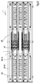
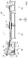
- a circulating chain 20 is arranged within a frame 30 of the transport device 100.
- both chain 20 and the fastened compartments 10 extend over the entire length of the transport device 100 both on the top of the transport device 100 for the transport of book blocks 1 in the transport direction indicated by the reference symbol T. , as well as empty compartments 10 on the underside of the transport device 100 for the return transport of the compartments 10 opposite to the transport direction T.
- the transport compartments 10 are fastened to the chain 20 at equal distances from each other.
- the compartments 10 have a shelf 12 and a side wall 14.
- Fig. 1 book blocks 1, which lie in the slightly inclined subjects, drawn. These book blocks 1 have a spine 2, flat sides 3, which are the cover pages of the book block, and a front side 5, which is opposite to the spine.
- the shelf 12 on the one hand a comb-like structure with recesses 16 and also additional openings 18th
- fans 50 are mounted, which generate an air flow 52 which is directed substantially against the spine 2 in the compartments 10 .
- the openings 18 or recesses 16 of the shelf allow direct contact between the air flow 52 and the spine 2, which is cooled by this air flow 52.
- the aim of the cooling is to cool a stick-bound bookbuck 1 so far after the glue has been applied to the spine 2, that a subsequent three-sided trimming of the book block 1 without damaging the book block 1 or bonding to the spine 2 can be done.
- a plurality of fans here three, as a group on a fan plate 54, which is fastened to the housing of the transport device 100.
- the fans 50 may thus be individually mounted on the fan plate 54 outside of the housing 30 and subsequently be inserted in groups with the fan plate 54 in the housing 30.
- a plurality of these fan plate 54 distributed over the width of the device 100 and over the length thereof.
- the fans 50 or fan groups are operated on a fan plate 54.
- the chain 20 is closed within the transport device 100, the transport device 100 then has corresponding, not shown pulleys at each end of the transport device 100, which are looped by the chain 20.
- Another embodiment in which the chain additionally extends over other parts of a cooling device 500 is shown in FIG. In Fig. 4, the same chain extends equally over a plurality of transport devices 100, 100 '.
- the chain 20 has known to those skilled, not shown segments, by means of which the chain 20 can be easily opened, extended and closed again.
- a cooling device 500 is shown. This is composed of a transport device 100, 100 'as described in FIGS. 1 and 2, and a docking unit 200 and a display unit 300 together.
- the application unit 200 has a front deflection roller 24 for the chain and an application bevel 210.
- the application slope 210 has passage openings 220 for the side walls 14 of the compartments 10, as can be seen in FIG.
- the insertion bevel 210 has an angle to the horizontal, which essentially corresponds to the angle of inclination of the side walls 14 of the compartments 10 to the vertical, so that the side wall 14 can be aligned with the insertion bevel 210. However, this is not mandatory.
- An unillustrated conveyor belt of a preceding apparatus transports a book block 1 with the spine 2 forward to the insertion bevel 210, which the book block 1 either slides down or is pushed by the conveyor belt, not shown.
- a compartment 10 is in a substantially horizontal orientation, so that the book block 1 is pushed onto the insertion bevel 210 without problems can be.
- the preceding compartment 10 is at least far enough removed in the supply of the existing book block 1, that it does not hinder the book block 1 on the insertion slant 210 and the subsequent compartment 10 takes the book block 1 lying on the insertion slant 210.
- the side wall 14 at the upper region is inclined a little further backwards. This facilitates the easier feeding of a book block along the lay-in bevel 210 into a waiting compartment 10.
- a delivery unit 300 which also carries the drive 310 of the entire cooling device 500.
- the attached below the transport plane drive 310 drives via a drive shaft 312 and a drive belt 313 a shaft 322, and the rear guide roller 22 of the chain 20.
- To the shaft 322 conveyor belts 320, 323, 324 are arranged. A gap is provided between these conveyor belts 320, 323, 324, so that the narrow side walls 14 (see FIG. 4) can descend through the plane of the conveyor belts 320, 323, 324 in order to return the trays 10 to the contactor unit 200 allow.
- the conveyor belts 320, 323, 324 are operated at a higher running speed than the running speed of the chain 20. Reached a book block 1 in a tray 10 now this slightly upwardly inclined faster conveyor belts 320, 323, 324, they come into contact with the spine 2, pull it from the shelf 12 and accelerate the book block 1 further in the transport direction T, so the book block 1 has been conveyed along with the spine 2 as far as the conveyor belts 320, 323, 324, so that the side walls 14 which diverge between the conveyor belts 320, 323, 324 can no longer come into contact with the book block 1. As a result, the book block 1 after leaving the cooling device 500 has the same orientation as in the supply to the cooling device 500.
- the side wall 14 of the compartments 10 is divided into two and consists essentially of two narrow parallel, slightly inclined back ridges. These webs have a distance to each other, which corresponds at least to the smallest format of a book block 1, which is to be transported with this device 100, 500.
- the book blocks 1 in the middle of the Transport device 100 transported, the center line of the book blocks in the transport direction T thus corresponds substantially to the center line of the transport device 100, 100 '.
- side boundaries 330 for the book blocks 1 are arranged next to the transport path in the delivery unit 300. These side boundaries 330 are movably mounted on brackets 332 to crossbars 335. The transverse rods 335 are mounted in device-fixed struts 334. Although the side limits 330 of the transport path are shown only for the delivery unit 300, it is clear that the transport devices 100, 100 'may also have side borders that secure the transport of the book blocks 1 along the transport direction T.
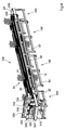
- FIGS. 5 and 6 show a further embodiment 500 'of the cooling device 500, 500' according to the invention.
- the cooling device 500 ' may be arranged downstream of the device for transferring book blocks.
- the second conveyor belt 70 transports the book block 1 with the spine 2 ahead to an insertion bevel on which the book block 1 is inserted into a compartment 510 '.
- Tray 510 ' has a shelf 512' and a side wall 514 '.
- the side wall 514 'and the shelf 512' are slightly inclined to the transport direction T, so that the book block 1 can be transported in the tray 510 'tilt-proof along the transport direction T.
- the spine 2 rests on the shelf 512 'and a flat side 3 of the book block 1 on a side wall 514' of the tray 510 '.
- the compartments 510 ' After traversing the cooling path of the cooling device 500 ', at which these fans 550' are arranged, the compartments 510 'reach a ramp 539', where they are transported obliquely upwards.
- guide elements 530' for the lateral alignment of the book blocks 1 in the subjects 510 'are provided, which align the book blocks 1 again centrally to the transport direction.
- Like guide elements are also mounted in the entrance area of the cooling device 500 '.
- the transport device 100 or cooling device 500, 500 'according to the invention has been described in combination with adhesive bound book blocks 1. But it is also conceivable to transport other flat objects that require cooling, with a corresponding device. Also, negative cooling, ie, heating of flat objects, may be conceivable by replacing the coolant 50 with suitable heating means or by using a heated air flow moved by the fans 50 in other applications.
Landscapes
- Engineering & Computer Science (AREA)
- Mechanical Engineering (AREA)
- Auxiliary Devices For And Details Of Packaging Control (AREA)
Applications Claiming Priority (2)
| Application Number | Priority Date | Filing Date | Title |
|---|---|---|---|
| ITMI20041529 ITMI20041529A1 (it) | 2004-07-28 | 2004-07-28 | Dispositivo per la produzione di libri |
| ITMI20041527 ITMI20041527A1 (it) | 2004-07-28 | 2004-07-28 | Dispositivo trasportatore per mazzette di libri |
Publications (2)
| Publication Number | Publication Date |
|---|---|
| EP1621361A2 true EP1621361A2 (fr) | 2006-02-01 |
| EP1621361A3 EP1621361A3 (fr) | 2011-03-09 |
Family
ID=35238061
Family Applications (1)
| Application Number | Title | Priority Date | Filing Date |
|---|---|---|---|
| EP05106074A Withdrawn EP1621361A3 (fr) | 2004-07-28 | 2005-07-05 | Dispositif de transport pour blocs de livres |
Country Status (2)
| Country | Link |
|---|---|
| EP (1) | EP1621361A3 (fr) |
| DE (1) | DE102005031568A1 (fr) |
Cited By (3)
| Publication number | Priority date | Publication date | Assignee | Title |
|---|---|---|---|---|
| CN102001510A (zh) * | 2010-11-12 | 2011-04-06 | 深圳市精密达机械有限公司 | 一种用于书本立式输送机构 |
| CN104349905A (zh) * | 2012-05-02 | 2015-02-11 | 必诺·罗伊泽有限及两合公司 | 利用金属丝梳式或螺旋装订件或其他类似装订件制造本册的方法和装置 |
| CN108144668A (zh) * | 2017-12-29 | 2018-06-12 | 明光市海春米业有限公司 | 一种传送式冷米装置 |
Family Cites Families (5)
| Publication number | Priority date | Publication date | Assignee | Title |
|---|---|---|---|---|
| CH256852A (de) * | 1945-07-06 | 1948-09-15 | Whitticase Walter | Verfahren und Vorrichtung zum Binden von Büchern. |
| CH412796A (de) * | 1963-05-17 | 1966-05-15 | Mueller Hans Grapha Masch | Trocknungseinrichtung für klebegebundene Bücher |
| DE1270001B (de) * | 1964-12-04 | 1968-06-12 | Mueller Hans Grapha Masch | Trocknungs- und Kuehlvorrichtung fuer klebegebundene Broschueren |
| DE2224523A1 (de) * | 1972-05-19 | 1973-12-06 | Rahdener Maschf August | Verfahren zum trocknen der auf die buchblockruecken oder dgl. aufgetragenen klebstoffschicht und vorrichtung dazu |
| US4009498A (en) * | 1972-06-22 | 1977-03-01 | General Binding Corporation | Bookbinding system |
-
2005
- 2005-07-05 EP EP05106074A patent/EP1621361A3/fr not_active Withdrawn
- 2005-07-06 DE DE200510031568 patent/DE102005031568A1/de not_active Withdrawn
Cited By (3)
| Publication number | Priority date | Publication date | Assignee | Title |
|---|---|---|---|---|
| CN102001510A (zh) * | 2010-11-12 | 2011-04-06 | 深圳市精密达机械有限公司 | 一种用于书本立式输送机构 |
| CN104349905A (zh) * | 2012-05-02 | 2015-02-11 | 必诺·罗伊泽有限及两合公司 | 利用金属丝梳式或螺旋装订件或其他类似装订件制造本册的方法和装置 |
| CN108144668A (zh) * | 2017-12-29 | 2018-06-12 | 明光市海春米业有限公司 | 一种传送式冷米装置 |
Also Published As
| Publication number | Publication date |
|---|---|
| EP1621361A3 (fr) | 2011-03-09 |
| DE102005031568A1 (de) | 2006-03-23 |
Similar Documents
| Publication | Publication Date | Title |
|---|---|---|
| DE69103185T2 (de) | Verfahren und Vorrichtung zum Bilden von Stapeln von der Oberseite eines Stapels von Blättern in einer Maschine zur Herstellung von Verpackungen. | |
| DE2456046A1 (de) | Sortiervorrichtung | |
| EP0816265B1 (fr) | Dispositif pour ranger des feuilles de verre coupées | |
| DE3613315C2 (fr) | ||
| AT403908B (de) | Anordnung zum teilen von verbundglas | |
| AT396767B (de) | Kreissäge mit automatischem abtransport des schnittgutes | |
| EP1621361A2 (fr) | Dispositif de transport pour blocs de livres | |
| DE9301072U1 (de) | Sammelvorrichtung für Blätter zur Bildung von Blattstapeln | |
| EP3889087A1 (fr) | Dispositif de collecte et de transport destiné à la collecte et au transport de produits imprimés en forme de feuilles | |
| EP0822739B1 (fr) | Appareil automatisé de test de cartes de circuit électronique | |
| DE19845850C2 (de) | Vorrichtung zum Stapeln von Bögen | |
| AT396766B (de) | Einrichtung zum buntaufteilen von plattenförmigen werkstücken | |
| DE69504837T2 (de) | Eine magazinanordnung | |
| EP0885824B1 (fr) | Station d'emmagasinage | |
| DE102009045319B4 (de) | Formateinstellvorrichtung | |
| DE3019101C2 (fr) | ||
| DE2547114A1 (de) | Verfahren und vorrichtung zum ueberfuehren von staeben von einer streckbank zu einem foerderer | |
| WO2021113889A1 (fr) | Dispositif auxiliaire pour déplacer un seul ou une pluralité de cadres de ruche | |
| EP1479492A1 (fr) | Machine pour le traitement en continu de panneaux avec dispositif de support à l'entrée | |
| EP0457720B1 (fr) | Dispositif d'alimentation pour une machine pour l'assemblage de feuilles de placage en bande continue | |
| DE102007046377A1 (de) | Trocknungsvorrichtung | |
| WO2009124544A1 (fr) | Dispositif convoyeur pour installation d'aboutage par entures multiples de pièces de bois | |
| AT405508B (de) | Sortier- und stapeleinrichtung für plattenaufteilanlagen | |
| AT406952B (de) | Vakuum-eingabevorrichtung | |
| DE3616921C2 (fr) |
Legal Events
| Date | Code | Title | Description |
|---|---|---|---|
| PUAI | Public reference made under article 153(3) epc to a published international application that has entered the european phase |
Free format text: ORIGINAL CODE: 0009012 |
|
| AK | Designated contracting states |
Kind code of ref document: A2 Designated state(s): AT BE BG CH CY CZ DE DK EE ES FI FR GB GR HU IE IS IT LI LT LU LV MC NL PL PT RO SE SI SK TR |
|
| AX | Request for extension of the european patent |
Extension state: AL BA HR MK YU |
|
| PUAL | Search report despatched |
Free format text: ORIGINAL CODE: 0009013 |
|
| AK | Designated contracting states |
Kind code of ref document: A3 Designated state(s): AT BE BG CH CY CZ DE DK EE ES FI FR GB GR HU IE IS IT LI LT LU LV MC NL PL PT RO SE SI SK TR |
|
| AX | Request for extension of the european patent |
Extension state: AL BA HR MK YU |
|
| RIC1 | Information provided on ipc code assigned before grant |
Ipc: B42C 13/00 20060101ALI20110201BHEP Ipc: B65H 7/12 20060101ALI20110201BHEP Ipc: B65H 3/44 20060101ALI20110201BHEP Ipc: B65H 3/08 20060101AFI20110201BHEP |
|
| AKY | No designation fees paid | ||
| REG | Reference to a national code |
Ref country code: DE Ref legal event code: R108 |
|
| REG | Reference to a national code |
Ref country code: DE Ref legal event code: R108 Effective date: 20111116 |
|
| STAA | Information on the status of an ep patent application or granted ep patent |
Free format text: STATUS: THE APPLICATION IS DEEMED TO BE WITHDRAWN |
|
| 18D | Application deemed to be withdrawn |
Effective date: 20110910 |