EP1621380A2 - Store à enrouleur courbé avec butée pour ressort - Google Patents
Store à enrouleur courbé avec butée pour ressort Download PDFInfo
- Publication number
- EP1621380A2 EP1621380A2 EP05014625A EP05014625A EP1621380A2 EP 1621380 A2 EP1621380 A2 EP 1621380A2 EP 05014625 A EP05014625 A EP 05014625A EP 05014625 A EP05014625 A EP 05014625A EP 1621380 A2 EP1621380 A2 EP 1621380A2
- Authority
- EP
- European Patent Office
- Prior art keywords
- cap
- roller blind
- spring
- axis
- shaft
- Prior art date
- Legal status (The legal status is an assumption and is not a legal conclusion. Google has not performed a legal analysis and makes no representation as to the accuracy of the status listed.)
- Withdrawn
Links
- 230000008878 coupling Effects 0.000 claims abstract description 5
- 238000010168 coupling process Methods 0.000 claims abstract description 5
- 238000005859 coupling reaction Methods 0.000 claims abstract description 5
- 239000011324 bead Substances 0.000 claims description 4
- 230000006835 compression Effects 0.000 claims 1
- 238000007906 compression Methods 0.000 claims 1
- 238000004804 winding Methods 0.000 description 27
- 241001295925 Gegenes Species 0.000 description 1
- 238000006243 chemical reaction Methods 0.000 description 1
- 238000010276 construction Methods 0.000 description 1
- 238000011161 development Methods 0.000 description 1
- 230000018109 developmental process Effects 0.000 description 1
- 230000007774 longterm Effects 0.000 description 1
- 239000000463 material Substances 0.000 description 1
- 230000002093 peripheral effect Effects 0.000 description 1
- 238000007665 sagging Methods 0.000 description 1
Images


Classifications
-
- B—PERFORMING OPERATIONS; TRANSPORTING
- B60—VEHICLES IN GENERAL
- B60J—WINDOWS, WINDSCREENS, NON-FIXED ROOFS, DOORS, OR SIMILAR DEVICES FOR VEHICLES; REMOVABLE EXTERNAL PROTECTIVE COVERINGS SPECIALLY ADAPTED FOR VEHICLES
- B60J1/00—Windows; Windscreens; Accessories therefor
- B60J1/20—Accessories, e.g. wind deflectors, blinds
- B60J1/2011—Blinds; curtains or screens reducing heat or light intensity
- B60J1/2013—Roller blinds
- B60J1/2019—Roller blinds powered, e.g. by electric, hydraulic or pneumatic actuators
- B60J1/2027—Roller blinds powered, e.g. by electric, hydraulic or pneumatic actuators with a buckle-proof guided flexible actuating element acting on the draw bar for pushing or push-pulling, e.g. a Bowden cable
-
- B—PERFORMING OPERATIONS; TRANSPORTING
- B60—VEHICLES IN GENERAL
- B60J—WINDOWS, WINDSCREENS, NON-FIXED ROOFS, DOORS, OR SIMILAR DEVICES FOR VEHICLES; REMOVABLE EXTERNAL PROTECTIVE COVERINGS SPECIALLY ADAPTED FOR VEHICLES
- B60J1/00—Windows; Windscreens; Accessories therefor
- B60J1/20—Accessories, e.g. wind deflectors, blinds
- B60J1/2011—Blinds; curtains or screens reducing heat or light intensity
- B60J1/2013—Roller blinds
- B60J1/2033—Roller blinds characterised by the spring motor
-
- B—PERFORMING OPERATIONS; TRANSPORTING
- B60—VEHICLES IN GENERAL
- B60J—WINDOWS, WINDSCREENS, NON-FIXED ROOFS, DOORS, OR SIMILAR DEVICES FOR VEHICLES; REMOVABLE EXTERNAL PROTECTIVE COVERINGS SPECIALLY ADAPTED FOR VEHICLES
- B60J1/00—Windows; Windscreens; Accessories therefor
- B60J1/20—Accessories, e.g. wind deflectors, blinds
- B60J1/2011—Blinds; curtains or screens reducing heat or light intensity
- B60J1/2013—Roller blinds
- B60J1/2036—Roller blinds characterised by structural elements
-
- B—PERFORMING OPERATIONS; TRANSPORTING
- B60—VEHICLES IN GENERAL
- B60J—WINDOWS, WINDSCREENS, NON-FIXED ROOFS, DOORS, OR SIMILAR DEVICES FOR VEHICLES; REMOVABLE EXTERNAL PROTECTIVE COVERINGS SPECIALLY ADAPTED FOR VEHICLES
- B60J1/00—Windows; Windscreens; Accessories therefor
- B60J1/20—Accessories, e.g. wind deflectors, blinds
- B60J1/2011—Blinds; curtains or screens reducing heat or light intensity
- B60J1/2013—Roller blinds
- B60J1/2066—Arrangement of blinds in vehicles
- B60J1/2075—Arrangement of blinds in vehicles specially adapted for fixed windows
- B60J1/208—Arrangement of blinds in vehicles specially adapted for fixed windows for rear windows
-
- B—PERFORMING OPERATIONS; TRANSPORTING
- B60—VEHICLES IN GENERAL
- B60J—WINDOWS, WINDSCREENS, NON-FIXED ROOFS, DOORS, OR SIMILAR DEVICES FOR VEHICLES; REMOVABLE EXTERNAL PROTECTIVE COVERINGS SPECIALLY ADAPTED FOR VEHICLES
- B60J3/00—Antiglare equipment associated with windows or windscreens; Sun visors for vehicles
- B60J3/002—External sun shield, e.g. awning or visor
- B60J3/005—External sun shield, e.g. awning or visor for side windows
-
- B—PERFORMING OPERATIONS; TRANSPORTING
- B60—VEHICLES IN GENERAL
- B60Y—INDEXING SCHEME RELATING TO ASPECTS CROSS-CUTTING VEHICLE TECHNOLOGY
- B60Y2200/00—Type of vehicle
- B60Y2200/10—Road Vehicles
- B60Y2200/11—Passenger cars; Automobiles
Definitions
- the endeavor is therefore also to create curved Wickewellen, as shown for example in DE 103 38 900 A1.
- the actual winding shaft which is connected to the roller blind, consists of a number of straight shaft sections which are rotatably coupled together.
- the shaft sections are rotatably mounted together on a curved axis.
- the axle is clamped at one end to anchor it in the circumferential direction and in the axial direction.
- the other end is supported by means of a rotatably mounted on the cap cap, which passes through the cap through a spring rod, which is also fixed rigidly outside the axis.
- the spring rod carries at its in-axis end of the rigid spring abutment, while the outer spring abutment is anchored to the cap.
- the new window blind has a single axis rigidly anchored curved axis.
- the axis is, at least at one end, tubular.
- the winding shaft is rotatably mounted, which is composed of at least a shaft portion and a cap.
- the cap is also part of the bearing means of the axle and abutment for the spring.
- the cap is rotatably mounted on corresponding long-term agents and thus captivates the free end of the axle in the radial direction.
- the stationary spring abutment is seated in the at least partially tubular winding shaft.
- the axis itself becomes the stationary abutment for the spring motor.
- the existing in the prior art spring rod can be saved. Since the spring, which forms the spring motor, is flexible, it can be arbitrarily adapted to the curvature of the axis. In particular, it can create on the inside of the curvature on the axis, which contributes to the reduction of rattling noises. Forced positions between spring and axle and spring rod, as is the case in the prior art, are avoided.
- the axial bias that can generate the spring motor is simultaneously used to bias the tubular winding shaft together with cap in the axial direction.
- the individual shaft sections lie spielfei each other.
- the abutment can be formed in the simplest case by a flange which is produced by upsetting the tubular axis.
- the cap which is used to transmit the force from the spring motor to the shaft portions, may either have the shape of a flat disc with a corresponding driving toothing for the shaft portions, or be a cap with a bottom and a molded collar, with it is itself mounted on the outer peripheral surface of the axle.
- the cap is provided on its side adjacent to the rigid axle with a spring abutment, in which the spring spring serving as a helical spring is anchored rotationally fixed and axially secured.
- the fixed spring abutment consists of an insert, which is used in the rigid axis and there, for example, pressed by beads.
- Figure 1 illustrates the broken, cut-off rear region of a passenger car.
- the figure illustrates a view of the right inner side, which is a mirror image of the unillustrated left inner side.
- the presentation is simplified.
- interior body structures such as stiffening and fasteners are not shown because their representation for understanding the invention is not required.
- the representation of the body is schematic and does not recognize the existing cavities there.
- the illustrated body section 1 has a roof 2, from the side of a B-pillar 3 leads down to a bottom group, not shown. A corresponding B-pillar would be conceivable on the broken-off side of the vehicle.
- the roof 2 merges at its rear edge into a rear window 4. Laterally, the rear window ends at a C-pillar 5, which is located at a distance from the B-pillar 3.
- the C-pillar 5 carries an inner lining 6.
- a rear, right side door 7 is hinged to the B pillar 3 in a known manner.
- right side door 7 is a setback 8, to which a seat 9 and a rear seat back 11 belong.
- the rear seat 9 lies on a base surface 12 which belongs to the floor assembly and are formed in front of the foot wells 13.
- a rear shelf 15 extends to the lower edge of the rear window. 4
- the rear, right side door is provided in the usual manner for sedans with a side window 16.
- rear window roller blind 16 On the inside in front of the rear window 4 there is a rear window roller blind 16. Of the rear window roller blind 16 is partially extended roller blind 17 and one of lateral guide rails 18 can be seen.
- the guide rail 18 begins at the existing behind the rear seat backrest 11 shelf 15 and runs next to the side edge of the window.
- the parcel shelf 15 includes a continuous pull-out slot 20, from which the roller blind 18 runs out.
- the extension slot 20 is curved to approximate the curvature of the rear window 4.
- a curved winding shaft 21 is rotatably mounted on the blind sheet 18 is attached with an edge.
- the representation of the winding shaft 21 is highly schematic in Fig. 2, the details will be apparent from the following figures.
- the winding shaft 21 is biased by means of a schematically indicated spring motor 22 in the sense of winding the roller blind 18 on the winding shaft 21.
- a helical spring is provided, which is anchored at one end to the body and fixed at the other end in the winding shaft 21.
- the curvature of the winding shaft 21 corresponds to the curvature of the extension slot 20th
- the roller blind 17 has an approximately trapezoidal blank and is provided on its edge remote from the winding shaft 21 with a tubular loop 23. Through the tubular loop 23 performs a pull-out profile or bow, in the end pieces 24 and 25 telescopically are stored.
- the end pieces 24 and 25 have a neck portion 26 which has a smaller diameter than an adjoining guide member 27 which has the shape of a short cylindrical portion.
- the guide members 27 run in the guide rails 19, which are arranged adjacent to the two side edges of the rear window 4.
- the extended roller blind 18 Since both the winding shaft 21 and the extension profile are curved in the same way, the extended roller blind 18 describes a curved surface whose generatrix is a straight line. If possible, the blind sheet 18 does not brush against the edges of the pull-out slot 18.
- Each of the guide rails 19 includes an undercut guide groove 28 which opens in the direction of the roller blind 18 in a guide slot.
- each guide rail 19 is connected to a guide tube 29, 30, in which two bendable push members 31 and 32 are guided ausknickêt.
- the flexible thrust members 31 and 32 are so-called SU flexwellen. They consist of a cylindrical core, which is surrounded by a helically extending rib. In this way, a kind of flexible racks with all-round toothing is obtained.
- the guide tubes 29 and 30 connect the guide rails 19 with a geared motor 33.
- the geared motor 33 is composed of a permanent magnet DC motor 34 and a gear 35 together on the output shaft 36, a spur gear 37 rotatably seated.
- the gear 37 meshes with the two push members 31, 32 positively.
- the Thrust members 31, 32 pass tangentially to the diametrically opposite sides of the spur gear 37 and are guided for this purpose in corresponding bores 38, 39.
- the thrust members 31, 32 are selectively advanced or retracted.
- the movement of the thrust members 31, 32 follow the guide pieces 24, 25. These are held by means of the spring motor 22 against the free ends of the thrust members 31, 32 fitting, which are located in the guide grooves 28.
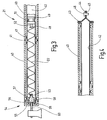
- the winding shaft 21 is, as the enlarged view reveals, composed of a plurality of axially adjacent tubular shaft portions 40 together.
- the rohrfömigen shaft sections 40 are positively coupled together at the joints at 41.
- the shaft portions on the front side tabs between which recesses or recesses are included which have the same shape as the tabs, such that the tabs on one side into the recesses on the opposite side of the other shaft portion 40 can intervene.
- this positive connection gives the possibility that the individual shaft sections 40 can tilt against each other, so as to approximate the desired curved course of the winding shaft 21 in a polygonal manner.
- the shaft sections 40 sit one behind the other on a tubular axis 42.
- the axis 42 is compressed at one end in FIG. 4 in the axial direction, whereby a radially outwardly projecting flange 43 is formed, which serves as an abutment for the immediately adjacent shaft portion 40.
- the wall material that forms the tubular axis 42 in the region of the flange 43 is double-layered.
- the remaining tubular part which adjoins the flange 43 is pressed flat, whereby a flat fastening plate is formed, with an opening 45 for a fastening element 46, for example a screw, a rivet or the like.
- the mounting plate 44 is formed by the forming integral part of the rohrfömigen axis 42nd
- the tubular shaft portions 40 are provided with inwardly projecting warts 47.
- the warts 47 each form groups, with the warts within a group lying on a circle concentric with the axis of the shaft portion 40. In each case a group of these warts 47 is provided in the vicinity of the respective front end of the shaft portion 40, as can be seen in the shaft portions 40 shown in full.
- the tubular shaft portion 40 is high in the area between the warts 47 at the two ends and is only in contact with the tubular axis 42 via the warts 47.
- a curvature of the tubular axis in the region between the ends of the tubular shaft portions 40 does not result in jamming.
- the schematically indicated spring motor 22 consists of a helical spring.
- the coil spring 22 is anchored at its end 48 in an abutment 49 which is inserted in the tubular axis 42. He is there pressed with the help of a bead 51, so that he can neither move in the axial direction nor can rotate. In the region of the bead 51, the spring abutment 49 is provided with a corresponding constriction.
- the spring abutment 49 carries in the direction of the spring 22 a short pin 52 with a transverse hole in which the spring end 48 is mounted.
- the other spring end 53 is coupled with a cup-shaped cap 54.
- the cup-shaped cap 54 is composed of a bottom 55 and an adjoining short collar 56.
- the collar 56 is provided at its free end face with the same coupling teeth as the adjacent shaft portion 40 so that a positive coupling between the cup-shaped cap 54 and the adjacent shaft portion 40 is made.
- the bottom 55 carries on its side adjacent to the tubular axis 42 a pin-shaped extension 57, in which the spring end 53 is hooked.
- a bearing pin 60 protrudes, which is firmly anchored in the body.
- the winding shaft 21 is biased in the sense of winding the blind sheet 18.
- the coil spring 22 is supported via the fixed spring abutment 49 in the body via the tubular axis 52 firmly held there.
- the other end of the coil spring 22 is rotatably coupled via the cup-shaped cap 54 with the adjacent tubular shaft portion 40, which in turn is connected without play or play with the wave portion 40 adjacent thereto. In this way, the torque generated by the coil spring 22 is transmitted to all shaft sections 40.
- the coil spring 22 is anchored not only in the rotational sense of the spring abutment 49 and the cup-shaped cap 54, but also fixed in the axial direction.
- the spring abutment 49 can thus be ensured that the coil spring 22 not only generates the drive torque, but also exerts a pulling force on the cup-shaped cap 54 to push the sequence of tubular shaft portions 40 frontally against each other.
- the reaction force is finally absorbed by the flange 43.
- the stationary bearing pin 60 in the blind hole 59 playfully engages is also free auskragnede in the end of the tubular shaft 40, which is not immediate bolted to the body, guided in the radial direction. All of the radial forces transmitted from the winding shaft 21 to the tubular axle 40 are introduced at one end via the plate 44 directly and at the other end by means of the rotatably mounted cup-shaped cap 54 into the body.
- a spring motor In a roller blind with a curved winding shaft, a spring motor is used in which a spring abutment is fixed within and on the axis on which the individual segments of the winding shaft are rotatably mounted. As a result, a mounting relief is created and the spring is able to apply to the wall of the axle to avoid rattling noises.
Landscapes
- Engineering & Computer Science (AREA)
- Mechanical Engineering (AREA)
- Operating, Guiding And Securing Of Roll- Type Closing Members (AREA)
Applications Claiming Priority (1)
| Application Number | Priority Date | Filing Date | Title |
|---|---|---|---|
| DE102004036948A DE102004036948B3 (de) | 2004-07-29 | 2004-07-29 | Gekrümmtes Fensterrollo mit innen liegendem Federwiderlager |
Publications (2)
| Publication Number | Publication Date |
|---|---|
| EP1621380A2 true EP1621380A2 (fr) | 2006-02-01 |
| EP1621380A3 EP1621380A3 (fr) | 2008-09-10 |
Family
ID=35229945
Family Applications (1)
| Application Number | Title | Priority Date | Filing Date |
|---|---|---|---|
| EP05014625A Withdrawn EP1621380A3 (fr) | 2004-07-29 | 2005-07-06 | Store à enrouleur courbé avec butée pour ressort |
Country Status (6)
| Country | Link |
|---|---|
| US (1) | US20060021721A1 (fr) |
| EP (1) | EP1621380A3 (fr) |
| JP (1) | JP4157882B2 (fr) |
| KR (1) | KR100724303B1 (fr) |
| CN (1) | CN1727632A (fr) |
| DE (1) | DE102004036948B3 (fr) |
Cited By (2)
| Publication number | Priority date | Publication date | Assignee | Title |
|---|---|---|---|---|
| EP1902879A3 (fr) * | 2006-09-25 | 2009-03-25 | BOS GmbH & Co. KG | Agencement de store |
| EP2638230A4 (fr) * | 2010-11-10 | 2015-08-05 | Markisol Holding Ab | Dispositif de précontrainte d'un mécanisme enrouleur |
Families Citing this family (4)
| Publication number | Priority date | Publication date | Assignee | Title |
|---|---|---|---|---|
| DE102010063450A1 (de) * | 2010-12-17 | 2012-06-21 | Bos Gmbh & Co. Kg | Rollosystem für ein Kraftfahrzeug |
| DE102014209144A1 (de) * | 2013-06-28 | 2014-12-31 | Bos Gmbh & Co. Kg | Schutzvorrichtung für einen Fahrzeuginnenraum |
| DE102015107573B3 (de) | 2015-05-13 | 2016-09-22 | Webasto SE | Anordnung für ein Wickelsystem und Wickelsystem für ein Fahrzeugdach |
| DE102016203382B4 (de) * | 2016-03-02 | 2017-11-23 | Bos Gmbh & Co. Kg | Beschattungsvorrichtung für einen Fahrzeuginnenraum |
Citations (1)
| Publication number | Priority date | Publication date | Assignee | Title |
|---|---|---|---|---|
| DE10338900A1 (de) | 2003-08-23 | 2005-03-17 | Bos Gmbh & Co. Kg | Gekrümmtes Fensterrollo für Kraftfahrzeuge |
Family Cites Families (15)
| Publication number | Priority date | Publication date | Assignee | Title |
|---|---|---|---|---|
| US516018A (en) * | 1894-03-06 | Shade-roller | ||
| US1071158A (en) * | 1913-04-26 | 1913-08-26 | Ishmael F Hurlbut | Curved shade-roller and curtain-rod. |
| DE1102581B (de) * | 1958-01-08 | 1961-03-16 | H T Golde G M B H & Co K G | Sonnenrollo, insbesondere fuer mit einem verschieb-baren Dacheinsatz verschliessbare OEffnungen in Daechern von Kraftfahrzeugen |
| US3092174A (en) * | 1959-02-06 | 1963-06-04 | Winn Stanley Pearson | Roller blind for curved windows and the like |
| US3069198A (en) * | 1960-04-11 | 1962-12-18 | Winn Stanley Pearson | Curved blinds for automobiles |
| JP3289223B2 (ja) * | 1991-05-23 | 2002-06-04 | 日本発条株式会社 | 遮蔽装置 |
| US5127459A (en) * | 1991-08-12 | 1992-07-07 | Markowitz Steven L | Adjustable rod for tear-away adjustable window shades |
| FR2779475A1 (fr) * | 1996-11-13 | 1999-12-10 | Farnier Et Penin Snc | Store a enrouleur galbe |
| NZ504541A (en) * | 1998-01-13 | 2000-12-22 | Formway Furniture Ltd | A table assembly with extensible modesty screen such that as top of table is adjusted vertically screen maintains privacy to user |
| DE19927384C1 (de) | 1999-06-16 | 2000-12-07 | Bos Gmbh | Trenneinrichtung mit variabler Rückzugskraft |
| US6079474A (en) * | 1999-08-06 | 2000-06-27 | Lin; Yung-Ching | Sun-shade assembly |
| DE10005951A1 (de) * | 2000-02-09 | 2001-08-16 | Bos Gmbh | Heckfensterrollo |
| NL1015212C1 (nl) * | 2000-05-17 | 2000-06-19 | Inalfa Ind Bv | Open-dakconstructie voor een voertuig. |
| DE10046553A1 (de) * | 2000-09-19 | 2002-04-04 | Bos Gmbh | Fensterrollo für gekrümmte oder nicht rechteckige Fahrzeugfenster |
| DE10158428B4 (de) * | 2001-11-29 | 2005-09-22 | Webasto Ag | Rolloanordnung |
-
2004
- 2004-07-29 DE DE102004036948A patent/DE102004036948B3/de not_active Expired - Lifetime
-
2005
- 2005-07-06 EP EP05014625A patent/EP1621380A3/fr not_active Withdrawn
- 2005-07-28 CN CNA2005100879683A patent/CN1727632A/zh active Pending
- 2005-07-28 US US11/191,703 patent/US20060021721A1/en not_active Abandoned
- 2005-07-28 KR KR1020050068702A patent/KR100724303B1/ko not_active Expired - Fee Related
- 2005-07-28 JP JP2005218318A patent/JP4157882B2/ja not_active Expired - Fee Related
Patent Citations (1)
| Publication number | Priority date | Publication date | Assignee | Title |
|---|---|---|---|---|
| DE10338900A1 (de) | 2003-08-23 | 2005-03-17 | Bos Gmbh & Co. Kg | Gekrümmtes Fensterrollo für Kraftfahrzeuge |
Cited By (2)
| Publication number | Priority date | Publication date | Assignee | Title |
|---|---|---|---|---|
| EP1902879A3 (fr) * | 2006-09-25 | 2009-03-25 | BOS GmbH & Co. KG | Agencement de store |
| EP2638230A4 (fr) * | 2010-11-10 | 2015-08-05 | Markisol Holding Ab | Dispositif de précontrainte d'un mécanisme enrouleur |
Also Published As
| Publication number | Publication date |
|---|---|
| DE102004036948B3 (de) | 2006-03-23 |
| EP1621380A3 (fr) | 2008-09-10 |
| JP4157882B2 (ja) | 2008-10-01 |
| JP2006036201A (ja) | 2006-02-09 |
| CN1727632A (zh) | 2006-02-01 |
| KR20060048835A (ko) | 2006-05-18 |
| US20060021721A1 (en) | 2006-02-02 |
| KR100724303B1 (ko) | 2007-06-04 |
Similar Documents
| Publication | Publication Date | Title |
|---|---|---|
| EP1598517B1 (fr) | Volet roulant avec entraînement par ressort spiral | |
| EP1666291B1 (fr) | Store à enrouler de fenêtre avec montage simplifié | |
| EP1859976B1 (fr) | Volet roulant avec entraînement silencieux par ressort en spirale | |
| EP1894758B1 (fr) | Store de fenêtre latérale | |
| EP1375219B1 (fr) | Store à enrouleur pour lunette arrière avec boîtier levant | |
| EP2060421B1 (fr) | Agencement de store doté d'un entraînement à friction réduite | |
| DE10339583B4 (de) | Aus Kunststoff gespritzte Führungsschiene | |
| DE102007012281A1 (de) | Automatisch betätigbares Seitenfensterrollo | |
| DE10005951A1 (de) | Heckfensterrollo | |
| EP1905625A1 (fr) | Store doté d'un rail de guidage sans contre-dépouille | |
| EP1932700A2 (fr) | Store de fenêtre triangulaire pour véhicules automobiles | |
| EP1736335A2 (fr) | Store à enrouleur pour fenêtre arrière avec obturateur de fente par le tiroir | |
| EP1533158A2 (fr) | Store à enrouleur pour vitres latérales | |
| EP1510382B1 (fr) | Store à enroleur courbé pour véhicules | |
| DE102005023967B4 (de) | Fensterrollo mit längsverstellbarer Wickelwelle | |
| DE102007039255A1 (de) | Heckscheibenrollo mit Winkeltragschiene | |
| EP1621380A2 (fr) | Store à enrouleur courbé avec butée pour ressort | |
| DE10204331A1 (de) | Rolloartige Anordnung mit längsgeteilter Wickelwelle | |
| EP1707412A2 (fr) | Store pour vitre latérale avec un tube enrouleur coulissant | |
| DE102005030707A1 (de) | Fensterrollo für Kraftfahrzeuge mit formschlüssigem Anschlag auf dem Betätigungsglied | |
| DE102016208896B4 (de) | Beschattungsvorrichtung für eine Fahrzeugscheibe | |
| DE102018204253A1 (de) | Spindelantrieb und Verfahren zu dessen Herstellung | |
| EP2062767B1 (fr) | Store de véhicule doté d'un ressort enrouleur et d'un noyau de ressort | |
| EP1520740A2 (fr) | Store enrouleur avec tiroir composé de deux parties | |
| DE202005020696U1 (de) | Fensterrollo für Kraftfahrzeuge mit formschlüssigem Anschlag auf dem Betätigungsglied |
Legal Events
| Date | Code | Title | Description |
|---|---|---|---|
| PUAI | Public reference made under article 153(3) epc to a published international application that has entered the european phase |
Free format text: ORIGINAL CODE: 0009012 |
|
| AK | Designated contracting states |
Kind code of ref document: A2 Designated state(s): AT BE BG CH CY CZ DE DK EE ES FI FR GB GR HU IE IS IT LI LT LU LV MC NL PL PT RO SE SI SK TR |
|
| AX | Request for extension of the european patent |
Extension state: AL BA HR MK YU |
|
| PUAL | Search report despatched |
Free format text: ORIGINAL CODE: 0009013 |
|
| AK | Designated contracting states |
Kind code of ref document: A3 Designated state(s): AT BE BG CH CY CZ DE DK EE ES FI FR GB GR HU IE IS IT LI LT LU LV MC NL PL PT RO SE SI SK TR |
|
| AX | Request for extension of the european patent |
Extension state: AL BA HR MK YU |
|
| 17P | Request for examination filed |
Effective date: 20090304 |
|
| STAA | Information on the status of an ep patent application or granted ep patent |
Free format text: STATUS: THE APPLICATION HAS BEEN WITHDRAWN |
|
| AKX | Designation fees paid |
Designated state(s): DE FR GB |
|
| 18W | Application withdrawn |
Effective date: 20090418 |