EP2060421B1 - Agencement de store doté d'un entraînement à friction réduite - Google Patents
Agencement de store doté d'un entraînement à friction réduite Download PDFInfo
- Publication number
- EP2060421B1 EP2060421B1 EP08018219A EP08018219A EP2060421B1 EP 2060421 B1 EP2060421 B1 EP 2060421B1 EP 08018219 A EP08018219 A EP 08018219A EP 08018219 A EP08018219 A EP 08018219A EP 2060421 B1 EP2060421 B1 EP 2060421B1
- Authority
- EP
- European Patent Office
- Prior art keywords
- roller blind
- arrangement according
- linear drive
- window
- window roller
- Prior art date
- Legal status (The legal status is an assumption and is not a legal conclusion. Google has not performed a legal analysis and makes no representation as to the accuracy of the status listed.)
- Not-in-force
Links
- 238000004804 winding Methods 0.000 claims description 30
- 230000009471 action Effects 0.000 description 2
- 238000010276 construction Methods 0.000 description 2
- 238000009434 installation Methods 0.000 description 2
- 238000012544 monitoring process Methods 0.000 description 2
- 230000008901 benefit Effects 0.000 description 1
- 230000000295 complement effect Effects 0.000 description 1
- 238000011161 development Methods 0.000 description 1
- 230000018109 developmental process Effects 0.000 description 1
- 230000004069 differentiation Effects 0.000 description 1
- 235000013601 eggs Nutrition 0.000 description 1
- 238000004519 manufacturing process Methods 0.000 description 1
- 230000007246 mechanism Effects 0.000 description 1
- 238000012986 modification Methods 0.000 description 1
- 230000004048 modification Effects 0.000 description 1
- 230000002093 peripheral effect Effects 0.000 description 1
- 230000009467 reduction Effects 0.000 description 1
- 239000003351 stiffener Substances 0.000 description 1
- 238000009423 ventilation Methods 0.000 description 1
Images

Classifications
-
- B—PERFORMING OPERATIONS; TRANSPORTING
- B60—VEHICLES IN GENERAL
- B60J—WINDOWS, WINDSCREENS, NON-FIXED ROOFS, DOORS, OR SIMILAR DEVICES FOR VEHICLES; REMOVABLE EXTERNAL PROTECTIVE COVERINGS SPECIALLY ADAPTED FOR VEHICLES
- B60J1/00—Windows; Windscreens; Accessories therefor
- B60J1/20—Accessories, e.g. wind deflectors, blinds
- B60J1/2011—Blinds; curtains or screens reducing heat or light intensity
- B60J1/2013—Roller blinds
- B60J1/2036—Roller blinds characterised by structural elements
- B60J1/2041—Blind sheets, e.g. shape of sheets, reinforcements in sheets, materials therefor
-
- B—PERFORMING OPERATIONS; TRANSPORTING
- B60—VEHICLES IN GENERAL
- B60J—WINDOWS, WINDSCREENS, NON-FIXED ROOFS, DOORS, OR SIMILAR DEVICES FOR VEHICLES; REMOVABLE EXTERNAL PROTECTIVE COVERINGS SPECIALLY ADAPTED FOR VEHICLES
- B60J1/00—Windows; Windscreens; Accessories therefor
- B60J1/20—Accessories, e.g. wind deflectors, blinds
- B60J1/2011—Blinds; curtains or screens reducing heat or light intensity
- B60J1/2013—Roller blinds
- B60J1/2019—Roller blinds powered, e.g. by electric, hydraulic or pneumatic actuators
- B60J1/2027—Roller blinds powered, e.g. by electric, hydraulic or pneumatic actuators with a buckle-proof guided flexible actuating element acting on the draw bar for pushing or push-pulling, e.g. a Bowden cable
-
- B—PERFORMING OPERATIONS; TRANSPORTING
- B60—VEHICLES IN GENERAL
- B60J—WINDOWS, WINDSCREENS, NON-FIXED ROOFS, DOORS, OR SIMILAR DEVICES FOR VEHICLES; REMOVABLE EXTERNAL PROTECTIVE COVERINGS SPECIALLY ADAPTED FOR VEHICLES
- B60J1/00—Windows; Windscreens; Accessories therefor
- B60J1/20—Accessories, e.g. wind deflectors, blinds
- B60J1/2011—Blinds; curtains or screens reducing heat or light intensity
- B60J1/2013—Roller blinds
- B60J1/2036—Roller blinds characterised by structural elements
- B60J1/205—Winding tubes, e.g. telescopic tubes or conically shaped tubes
-
- B—PERFORMING OPERATIONS; TRANSPORTING
- B60—VEHICLES IN GENERAL
- B60J—WINDOWS, WINDSCREENS, NON-FIXED ROOFS, DOORS, OR SIMILAR DEVICES FOR VEHICLES; REMOVABLE EXTERNAL PROTECTIVE COVERINGS SPECIALLY ADAPTED FOR VEHICLES
- B60J1/00—Windows; Windscreens; Accessories therefor
- B60J1/20—Accessories, e.g. wind deflectors, blinds
- B60J1/2011—Blinds; curtains or screens reducing heat or light intensity
- B60J1/2013—Roller blinds
- B60J1/2036—Roller blinds characterised by structural elements
- B60J1/2052—Guides
-
- B—PERFORMING OPERATIONS; TRANSPORTING
- B60—VEHICLES IN GENERAL
- B60J—WINDOWS, WINDSCREENS, NON-FIXED ROOFS, DOORS, OR SIMILAR DEVICES FOR VEHICLES; REMOVABLE EXTERNAL PROTECTIVE COVERINGS SPECIALLY ADAPTED FOR VEHICLES
- B60J1/00—Windows; Windscreens; Accessories therefor
- B60J1/20—Accessories, e.g. wind deflectors, blinds
- B60J1/2011—Blinds; curtains or screens reducing heat or light intensity
- B60J1/2013—Roller blinds
- B60J1/2066—Arrangement of blinds in vehicles
- B60J1/2069—Arrangement of blinds in vehicles of multiple blinds, e.g. more than one blind per window or per actuation system
-
- B—PERFORMING OPERATIONS; TRANSPORTING
- B60—VEHICLES IN GENERAL
- B60J—WINDOWS, WINDSCREENS, NON-FIXED ROOFS, DOORS, OR SIMILAR DEVICES FOR VEHICLES; REMOVABLE EXTERNAL PROTECTIVE COVERINGS SPECIALLY ADAPTED FOR VEHICLES
- B60J1/00—Windows; Windscreens; Accessories therefor
- B60J1/20—Accessories, e.g. wind deflectors, blinds
- B60J1/2011—Blinds; curtains or screens reducing heat or light intensity
- B60J1/2013—Roller blinds
- B60J1/2066—Arrangement of blinds in vehicles
- B60J1/2075—Arrangement of blinds in vehicles specially adapted for fixed windows
- B60J1/2083—Arrangement of blinds in vehicles specially adapted for fixed windows for side windows, e.g. quarter windows
-
- B—PERFORMING OPERATIONS; TRANSPORTING
- B60—VEHICLES IN GENERAL
- B60J—WINDOWS, WINDSCREENS, NON-FIXED ROOFS, DOORS, OR SIMILAR DEVICES FOR VEHICLES; REMOVABLE EXTERNAL PROTECTIVE COVERINGS SPECIALLY ADAPTED FOR VEHICLES
- B60J1/00—Windows; Windscreens; Accessories therefor
- B60J1/20—Accessories, e.g. wind deflectors, blinds
- B60J1/2011—Blinds; curtains or screens reducing heat or light intensity
- B60J1/2013—Roller blinds
- B60J1/2066—Arrangement of blinds in vehicles
- B60J1/2086—Arrangement of blinds in vehicles specially adapted for openable windows, e.g. side window
-
- B—PERFORMING OPERATIONS; TRANSPORTING
- B60—VEHICLES IN GENERAL
- B60J—WINDOWS, WINDSCREENS, NON-FIXED ROOFS, DOORS, OR SIMILAR DEVICES FOR VEHICLES; REMOVABLE EXTERNAL PROTECTIVE COVERINGS SPECIALLY ADAPTED FOR VEHICLES
- B60J3/00—Antiglare equipment associated with windows or windscreens; Sun visors for vehicles
- B60J3/002—External sun shield, e.g. awning or visor
- B60J3/005—External sun shield, e.g. awning or visor for side windows
Definitions
- a shading arrangement can be found, for example, at the rear side windows. These are divided into a substantially rectangular part and an approximately triangular part. In the rectangular part is the retractable disc of the side door while the triangular part is rigid. The two sections of the window are separated by a window strut.
- roller blind arrangements which are provided for such side windows consist of a horizontal winding shaft for the rectangular part and a vertically arranged winding shaft for the triangular part.
- the winding shaft for the triangular part is located at the window strut.
- the roller blind for the horizontal window is connected to a pull rod, which is guided at both ends in guide rails.
- This guide rail also serve for ausknickêt leadership of linear push members.
- These run in guide tubes to a drive device in the form of a geared motor with spur gear on the output shaft.
- the spur gear meshes with the teeth of the linear thrust links.
- a storage tube is additionally available for the unused empty section of each push element.
- the tension rod of the triangular roller blind is guided at one end in a guide rail, which also runs horizontally below the window sill.
- this guide rail leads an s- or Z-shaped guide tube to the same drive motor to achieve the drive for the triangular blind.
- the EP 1 306 251 A discloses a window blind assembly according to the preamble of claim 1.
- To the new window blind assembly include a first and a second winding shaft, which are rotatably mounted, each by itself. With the first winding shaft, a first roller blind is connected, the free edge is attached to an associated first tie rod. The second roller blind is anchored to the second winding shaft and also connected to an associated second pull rod.
- a drive device In order to move the first roller blind a drive device is provided with output gear, which meshes with a form-fitting manner with at least one first linear drive means. Thereby, the first roller blind can be moved by means of the drive means via the drive means.
- the movement for the second roller blind is derived from the movement of the first linear drive means.
- the first linear drive means is coupled by means of a gear with a loosely rotatable gear arrangement which also meshes with a second linear drive means.
- This new inventive concept makes it possible to save another long guide tube, which would otherwise be required to guide the second linear drive means to the drive means.
- the arrangement may be designed, for example, such that the first roller blind corresponds to the roller blind for the quadrangular window, wherein the pull rod is guided in two end guide rails.
- Each guide rail guides a first linear drive means, which is guided over a guide tube up to the drive device.
- the movement for the triangular blind is derived from the movement of that push member that runs at the window strut separating the two window sections.
- the movement of the triangular roller blinds takes place via a line-shaped drive means, which in this way is coupled only indirectly to the drive device.
- the guide rail for the triangular roller blind runs horizontally below the lower edge of the window and thus at right angles to the guide rail on the window strut.
- the gear assembly is seated in the inner corner at the point where the linear drive means for the triangular blind with the linear drive means, which is guided at the window strut, cut.
- the drive means for the triangular roller blind runs essentially only horizontally, so that practically no significant frictional forces occur here.
- the stroke for the triangular window roller blind is significantly shorter than the width of the quadrangular roller blind, which makes it possible to accommodate the storage tube directly in the extension of the guide rail for the triangular window roller blind.
- the frictional forces are significantly reduced.
- the production cost is significantly reduced, because no further guide tube must be bent, which connects the guide rail for the triangular window blind with the drive device according to the prior art.
- the arrangement according to the invention is particularly suitable, as can be seen from the above explanation, for window blind arrangements in which the winding shaft is arranged at an angle to one another.
- the drive device may be formed by an electric geared motor, wherein the output gear rotatably seated on the output shaft of the geared motor.
- the linear drive means may take the form of a rack.
- the linear drive means can also be designed as a perforated belt.
- two line-shaped drive means can be used either for the first or for the second roller blind, whichever is considered first to be available.
- the linear drive means can be designed so that they are subjected to pressure when extending the roller blind.
- tension rod can be assigned to this at least one guide rail.
- the guide rail can be configured for kink-proof guidance of the associated linear drive means.
- the first and / or the second winding shaft may be associated with a spring motor.
- the loose rotatable gear assembly may be formed by a single gear, or by a gear assembly comprising two rotatably coupled together gears. Each of the two gears is coupled with one of the linear drive means.
- the gear with the smallest diameter can be coupled with that linear drive means which actuates the roller blind with the smaller stroke.
- top and bottom or “front” and “rear” as well as “left” and “right” refer to the normal installation position or terminology in motor vehicles.
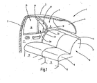
- FIG. 1 Fig. 11 illustrates the broken-away rear portion of a car.
- the figure illustrates a view of the right inner side, which is mirror-inverted to the unillustrated left inner side.
- the presentation is simplified.
- internal body structures such as stiffeners and fasteners, are not shown since their representation is not required for understanding the invention.
- the illustrated body section 1 has a roof 2, from the side of a B pillar 3 down to a floor group, not shown leads.
- a corresponding B-pillar would be conceivable on the broken-off side of the vehicle.
- the roof 2 merges at its rear edge into a rear window 4. Laterally, the rear window 4 ends at a C-pillar 5, which is located at a distance from the B-pillar 3.
- the C-pillar carries an inner lining 6.
- a rear right side door is hinged to the B-pillar in the known manner.
- a rear seat 8 At the height of the rear right side door is a rear seat 8 to which a seat 9 and a rear seat back 11 belong.
- the rear seat 9 lies on a base surface 12 which belongs to the floor assembly and are formed in front of the foot wells 13.
- a rear shelf 14 extends to the lower edge of the rear window. 4
- the rear right side door 7 is provided in the usual manner for sedans with a side window 15.
- the side window 15 is divided into a first window section 16 and a rear second window section 17.
- the first window section 16 has a substantially rectangular shape and is bounded to the rear by a guide column 18, which simultaneously represents an edge of the second window section 17.
- the second window section 17 is delimited relative to the guide column 18 by a door frame 19 which, together with the guide column 17, defines the shape of the second window section 16. He is, as shown, approximately triangular.
- the window 15 is associated with a side window blind 20.
- the basic structure of the side window roller blind 20 is in Fig. 2 shown in detail.
- FIG. 2 shows the door 7 highly schematic without interior trim. Evident is a door body 21, above which the window frame 19 rises. The door body 21 ends at a lower edge of the window 22.
- the partial blind 23 serves to shade the rectangular area 16 while the window shade 24 serves to shade the triangular section 17.
- To the window roller blind 23 includes a winding shaft 25 which is mounted below the lower window edge 2 in the door body 21.
- the winding shaft 25 is parallel to the lower edge of the window.
- a roller blind 26 is fixed with an edge whose other edge 27 is attached to a pull rod 28.
- Inside the winding shaft 25 is a known spring motor, which is adapted to bias the winding shaft in the sense of Aufwicklns the roller blind 26 on the winding shaft 25.
- the pull rod 28 is guided in two lateral guide rails 29 and 31.
- the guide rails 29 and 31 run alongside the side vertical window edges of the window portion 16. That is, the guide rail 29 is located in the left vertical portion of the window frame 19 while the guide rail 31 is housed in the guide roller 18.
- Both guide rails 29, 31 extend to below the lower edge of the window 22 into the door frame 21 into it.
- a guide tube closes 32, which leads to a gear housing 33 of a gear motor 34.
- a storage pipe 35th With the guide tube 32 is aligned on the other side of the gear housing 33, a storage pipe 35th
- a guide tube 37 leads to the gear housing 33 of the drive gear motor 34.
- a storage tube 38th is aligned with the guide tube 37.
- To the window blind 24 includes a arranged below the Fehnsterunterkante 22 guide rail 39, which extends from the intermediate gear 36.
- a further winding shaft 41 is rotatably mounted on the guide column 19, at the one edge with a triangular roller blind 42 is attached.
- the winding shaft 41 includes a known spring motor similar to the winding shaft 25 to bias the winding shaft 41 with a sense of rotation, which endeavors to wind the roller blind 42 on the winding shaft 41.
- a small contours 43 At the top of the roller blind 42 is a small contours 43, which is attached to an arm 44 which projects into the guide rail 39 into it.
- FIG. 3 shows schematically, in a perspective sectional view, the structure of the intermediate gear 36th
- the guided linear thrust links in the form of fully toothed flexible racks. Of these Thrust members are in FIG. 3 to recognize the two tension members 45 and 46. Another similarly constructed push member moves through the guide tube 32 and connects the geared motor 34 with the left end of the pull rod 28 which is guided in the guide rail 29.
- Each of the two tension members 45 and 46 consists of a cylindrical core 47, around which helically a rib 48 winds around, which is fixedly connected to the soul 47. This creates a kind of fully toothed flexible rack. With the help of the rib 48, a pushing or pushing force can be transmitted to the core 47.
- the intermediate gear 36 has a housing 51 which contains two right-angled through-holes 52 and 53 extending to each other.
- the two through holes 52 and 53 are laterally offset from each other so that they do not intersect each other.
- the diameter of the through-holes 52 and 53 corresponds to the outer diameter of the thrust members 45, 46 according to above the apex line of the rib 48.
- a chamber 54 in which a gear arrangement is rotatably mounted on an axle 56.
- the axis 56 is perpendicular to two mutually parallel planes, one of which contains the axis of the through hole 52 and the other the axis of the through hole 53.
- the gear assembly 55 includes a large gear 57 and a smaller gear 58.
- Both gears 57 and 58 are spur gears and provided with eggs gearing on the outer peripheral surface, so with the rib 58 of the 45 or 46 can comb.
- the two gears 57 and 58 are connected coaxially with each other rotatably.
- the shaft 56 is located so that the gear end of the large gear 57 is inserted into the through hole 53 to be engaged with the pushing member 45 as shown.
- the axis 56 is located so that the smaller gear 58 can dive into the through hole 52 so that the gear end of the spur gear 58 can clamp the form-fitting with the thrust member 46.
- the guide rail 39 In extension of the through hole 52, the guide rail 39 is connected to the rear, while in the opposite direction, a storage tube 59 is connected, that the slack side of the thrust member 46 receives.
- the guide rail 39 includes a guide groove 61.
- the cross section of the guide groove 61 is composed of a cylindrical guide chamber 62 and a rectangular slot 63 whose width is smaller than the diameter of the groove chamber 62. This creates an undercut guide groove 61, in which a sliding block 64 is guided, with which the arm 44 is connected.
- the width of the slot 63 corresponds to the thickness of the arm 44.
- the thrust member 46 is withdrawn from the guide rail 39, so that here too the winding of the roller blind 42 on the winding shaft 41 is not hindered by the pusher member 41.
- a switch activates the geared motor 34.
- This drives a gear, which meshes with the thrust members for the window blind 23 in engagement. It pulls the associated thrust members out of the storage tubes 35 and 38 and advances them toward the top of the guide rails 28 and 31.
- push the two push members namely the thrust member 45 in which in the guide rail 31 and the thrust member in the guide rail 29, the pullout rod 28 in front of him up, whereby the roller blind 26 is unwound from the winding shaft 25 against the action of the spring motor.
- This push member corresponds in its construction to the push member 45 FIG. 3 ,
- the drive movement for extending the roller track 42 is derived from the movement of the push member 45 that drives the right or rear end of the pull rod 28 of the window blind 23.
- the gear assembly 55 is rotated in a clockwise direction in rotation. The rotational movement is slip-free, because the gear 57 is positively engaged with the rib 48 of the thrust member 45.
- the gear 58 Since the two gears 57 and 58 are rotatably connected to each other, the gear 58 is also rotated clockwise in rotation and thus pushes the thrust member 46 based on FIG. 3 extends to the right close to the thrust member 46 above the gear 58.
- the feed movement of the thrust member 46 based on FIG. 3 to the right, ie in the vehicle to the rear moves the sliding block 54 to the rear end of the door and takes over the arm 44, the Kontiety 43 of the blind sheet 42 with to unravel the roller blind 42 in front of the triangular window 17.
- the retraction happens analogously in the opposite direction.
- the user actuates the gear motor 34 with the opposite rotational movement, whereby the thrust members are withdrawn from the two guide rails 29 and 31.
- the downward movement of the pressure member 45 rotates the gear assembly 55 in the counterclockwise direction, causing the pusher member 46 to retract from the guide rail 39.
- the spring motors in the winding shafts 25 and 41, the associated roller blinds 26 and 62 auswickeln to the extent that they allow the push members.
- the guide tubes or storage tubes for the thrust members are curved and twisted, the greater the friction loss therein.
- not another guide tube is used to drive the triangular rear roller blind 24, which connects the guide rail 39 with the geared motor 34.
- Such a guide tube must be bent z-shaped or s-shaped and generates correspondingly much friction.
- the movement for the thrust member 46 is derived from the movement of the thrust member 45, which makes it possible to place the drive source for the thrust member 46 in the form of the intermediate gear 51 at a position which is a practically elongated course of the thrust member 46th allows.
- the thrust member 46 runs straight into the guide rail 39 and also the storage tube 59 which receives the slack side of the thrust member 46 may be arranged to extend in a straight line below the lower edge of the window 22. The friction experienced by the thrust member 46 in the guide rail 39 and the storage tube 59 is thereby minimal.
- the reduction of the frictional forces in the thrust member 46 for driving the triangular rear window blind 24 also brings with it the advantage that the anti-pinch is better to realize.
- the anti-jamming protection is usually achieved by monitoring the current for the motor in the extended mode. The higher the friction losses, the greater the motor current even with a properly running roller blind, so that a differentiation between free-running roller blind and pinched body parts becomes difficult. If, on the other hand, the friction is small, anti-pinch protection is easier to accomplish with the aid of current monitoring.
- the two gears 57 and 58 are sized in their effective diameter to accommodate the differential stroke of the shade 26 relative to the shade 42.
- a side window roller blind for a motor vehicle is composed of two blinds.
- One partial blind is used for shading the triangular area and the other for shading the quadrangular area.
- To extend the roller blind ausknickêt für guided push elements are used.
- the movement of the thrust member for the triangular blind is derived from the movement of the adjacent thrust member for the rectangular blind. As a result, complicated laid guide tubes for the thrust member of the triangular blinds are avoided.
Landscapes
- Engineering & Computer Science (AREA)
- Mechanical Engineering (AREA)
- Operating, Guiding And Securing Of Roll- Type Closing Members (AREA)
Claims (16)
- Agencement de store de fenêtre pour véhicules automobiles,
comprenant un premier arbre d'enroulement (25, 41) qui est monté tournant,
comprenant une première bande de store (26) qui est fixée au premier arbre d'enroulement (25) et est reliée à une première barre de traction (27),
comprenant un dispositif d'entraînement (34) qui présente une roue dentée motrice,
comprenant au moins un premier moyen d'entraînement (45) linéaire qui relie la roue dentée de sortie du dispositif d'entraînement (34) à la première barre de traction (27)
comprenant un deuxième arbre d'enroulement (41) qui est monté tournant,
comprenant une deuxième bande de store (42) qui est fixée au deuxième arbre d'enroulement (41) et est reliée à une deuxième barre de traction (43),
caractérisé par le fait qu'il comporte un agencement de roues dentées (55) pouvant tourner librement, qui est en prise avec le premier moyen d'entraînement (45) linéaire, en engrenant par complémentarité de formes avec celui-ci, et
par le fait qu'il comporte au moins un deuxième moyen d'entraînement (46) linéaire qui engrène par complémentarité de formes avec l'agencement de roues dentées (55) pouvant tourner librement, en vue d'accoupler ledit agencement (55), tournant librement, avec la deuxième bande de store (42). - Agencement de store de fenêtre selon la revendication 1, caractérisé par le fait qu'il est dimensionné pour une fenêtre latérale (15) divisée.
- Agencement de store de fenêtre selon la revendication 1, caractérisé par le fait que les deux arbres d'enroulement (25, 41) sont disposés en formant un angle l'un avec l'autre.
- Agencement de store de fenêtre selon la revendication 1, caractérisé par le fait que le dispositif d'entraînement (34) comprend un motoréducteur, la roue dentée motrice étant accouplée avec l'arbre de sortie du motoréducteur ou étant montée sur celui-ci.
- Agencement de store de fenêtre selon la revendication 1, caractérisé par le fait que le premier et/ou le deuxième moyen d'entraînement (45, 46) linéaire se présente sous la forme d'une crémaillère.
- Agencement de store de fenêtre selon la revendication 1, caractérisé par le fait que le premier et/ou le deuxième moyen d'entraînement (45, 46) linéaire se présente sous la forme d'une crémaillère dotée d'une denture sur tout le pourtour.
- Agencement de store de fenêtre selon la revendication 1, caractérisé par le fait que le premier et/ou le deuxième moyen d'entraînement (45, 46) linéaire se présente sous la forme d'une bande perforée.
- Agencement de store de fenêtre selon la revendication 1, caractérisé par le fait qu'il y a deux premiers moyens d'entraînement (45) linéaires)
- Agencement de store de fenêtre selon la revendication 1, caractérisé par le fait que les moyens d'entraînement (45, 46) linéaires sont sollicités en compression lors du déroulement du store.
- Agencement de store de fenêtre selon la revendication 1, caractérisé par le fait que les moyens d'entraînement (45, 46) linéaires sont guidés, au moins par portions, de manière à résister au flambage.
- Agencement de store de fenêtre selon la revendication 1, caractérisé par le fait qu'au moins un rail de guidage (29, 32, 39) est associé à la première et/ou à la deuxième barre de traction (27, 43).
- Agencement de store de fenêtre selon la revendication 11, caractérisé par le fait que le rail de guidage (29, 32, 39) sert au guidage, avec résistance au flambage, du moyen d'entraînement (45, 46) linéaire associé.
- Agencement de store de fenêtre selon la revendication 1, caractérisé par le fait que le premier et/ou le deuxième arbre d'enroulement (25, 41) peut être entraîné par l'intermédiaire d'un moteur à ressort associé.
- Agencement de store de fenêtre selon la revendication 1, caractérisé par le fait que l'agencement de roues dentées (55) tournant librement est formé d'une seule roue dentée.
- Agencement de store de fenêtre selon la revendication 1, caractérisé par le fait que l'agencement de roues dentées (55) tournant librement présente deux roues dentées (57, 58) accouplées l'une avec l'autre de façon solidaire en rotation, dont une roue dentée (57, 58) est accouplée avec un moyen d'entraînement (45, 46) linéaire et l'autre roue dentée (57, 58) est accouplée avec l'autre moyen d'entraînement (45, 46) linéaire.
- Agencement de store de fenêtre selon la revendication 15, caractérisé par le fait que la roue dentée (58) de plus petit diamètre est accouplée avec le moyen d'entraînement (46) linéaire qui actionne la bande de store (42) avec la plus petite course.
Applications Claiming Priority (1)
| Application Number | Priority Date | Filing Date | Title |
|---|---|---|---|
| DE102007054694A DE102007054694A1 (de) | 2007-11-14 | 2007-11-14 | Rolloanordnung mit verminderter Reibung in den Antriebsgabeln |
Publications (2)
| Publication Number | Publication Date |
|---|---|
| EP2060421A1 EP2060421A1 (fr) | 2009-05-20 |
| EP2060421B1 true EP2060421B1 (fr) | 2010-10-27 |
Family
ID=40303478
Family Applications (1)
| Application Number | Title | Priority Date | Filing Date |
|---|---|---|---|
| EP08018219A Not-in-force EP2060421B1 (fr) | 2007-11-14 | 2008-10-17 | Agencement de store doté d'un entraînement à friction réduite |
Country Status (5)
| Country | Link |
|---|---|
| EP (1) | EP2060421B1 (fr) |
| JP (1) | JP2009120193A (fr) |
| KR (1) | KR101477997B1 (fr) |
| CN (1) | CN101492993B (fr) |
| DE (2) | DE102007054694A1 (fr) |
Families Citing this family (14)
| Publication number | Priority date | Publication date | Assignee | Title |
|---|---|---|---|---|
| JP5207397B2 (ja) * | 2009-05-21 | 2013-06-12 | 株式会社椿本チエイン | カーテン開閉装置 |
| JP5638288B2 (ja) | 2010-06-11 | 2014-12-10 | 芦森工業株式会社 | 車両用ウインドウシェード装置 |
| JP5427732B2 (ja) * | 2010-08-26 | 2014-02-26 | 本田技研工業株式会社 | 車両用ブラインド装置 |
| JP5719585B2 (ja) * | 2010-12-27 | 2015-05-20 | 芦森工業株式会社 | シェード装置 |
| JP6171657B2 (ja) * | 2013-07-19 | 2017-08-02 | スズキ株式会社 | サンシェードの構造 |
| KR20180019222A (ko) * | 2015-06-22 | 2018-02-23 | 보스 게엠베하 운트 코. 카게 | 차량의 2 부분 측면 윈도우 구성을 위한 차양 장치 |
| CN105774484B (zh) * | 2016-03-14 | 2017-11-24 | 吉林大学 | 一种太阳能供电的车窗卷帘驱动机构及其使用方法 |
| CN105691156B (zh) * | 2016-03-14 | 2017-12-05 | 上海世德子汽车零部件有限公司 | 一种用于车窗卷帘的驱动设备及其使用方法 |
| DE102016206301B4 (de) * | 2016-04-14 | 2017-11-30 | Bos Gmbh & Co. Kg | Beschattungssystem für ein Kraftfahrzeug |
| CN105667274B (zh) * | 2016-04-19 | 2019-05-14 | 南通伟恩汽车配件有限公司 | 天窗遮阳帘 |
| KR102804891B1 (ko) * | 2020-02-07 | 2025-05-09 | 현대자동차주식회사 | 서브 커튼을 구비한 도어 커튼 어셈블리 |
| KR102872954B1 (ko) * | 2020-07-09 | 2025-10-17 | 현대자동차주식회사 | 차량용 전동커튼 장치 |
| CN115320342B (zh) * | 2022-07-19 | 2025-08-05 | 宁波精成车业有限公司 | 一种用于汽车后座侧帘的电动卷帘驱动装置 |
| CN119611015B (zh) * | 2025-01-09 | 2025-11-11 | 重庆长安汽车股份有限公司 | 一种车载遮阳装置以及车辆 |
Family Cites Families (6)
| Publication number | Priority date | Publication date | Assignee | Title |
|---|---|---|---|---|
| DE50000785D1 (de) * | 2000-03-03 | 2003-01-02 | Schwab Technik Gmbh | Scheibenrollo-Vorrichtung für Fahrzeugscheiben |
| DE10151872B4 (de) * | 2001-10-24 | 2007-10-04 | Bos Gmbh & Co. Kg | Geteiltes Fensterrollo für Kraftfahrzeuge |
| DE10215322A1 (de) * | 2002-04-02 | 2003-10-16 | Brose Fahrzeugteile | Sonnenschutzrollo für ein Fahrzeugfenster |
| DE102004036075B3 (de) * | 2004-07-24 | 2006-02-16 | Bos Gmbh & Co. Kg | Anordnung für Seitenfensterrollo |
| DE202004020106U1 (de) * | 2004-12-23 | 2006-04-27 | Brose Fahrzeugteile Gmbh & Co. Kommanditgesellschaft, Coburg | Fensterrollo für ein Fahrzeugfenster |
| DE102005036318A1 (de) * | 2005-07-29 | 2007-02-01 | Bos Gmbh & Co. Kg | Fensterrollo mit glatten Schubgliedern |
-
2007
- 2007-11-14 DE DE102007054694A patent/DE102007054694A1/de not_active Withdrawn
-
2008
- 2008-10-17 EP EP08018219A patent/EP2060421B1/fr not_active Not-in-force
- 2008-10-17 DE DE502008001630T patent/DE502008001630D1/de active Active
- 2008-11-06 KR KR1020080109829A patent/KR101477997B1/ko not_active Expired - Fee Related
- 2008-11-13 CN CN2008101738845A patent/CN101492993B/zh not_active Expired - Fee Related
- 2008-11-14 JP JP2008292807A patent/JP2009120193A/ja active Pending
Also Published As
| Publication number | Publication date |
|---|---|
| DE102007054694A1 (de) | 2009-05-20 |
| CN101492993B (zh) | 2013-03-13 |
| CN101492993A (zh) | 2009-07-29 |
| KR101477997B1 (ko) | 2014-12-31 |
| JP2009120193A (ja) | 2009-06-04 |
| DE502008001630D1 (de) | 2010-12-09 |
| EP2060421A1 (fr) | 2009-05-20 |
| KR20090049991A (ko) | 2009-05-19 |
Similar Documents
| Publication | Publication Date | Title |
|---|---|---|
| EP2060421B1 (fr) | Agencement de store doté d'un entraînement à friction réduite | |
| EP1970235B1 (fr) | Store de fenêtre latérale doté d'un entraînement à corde | |
| EP1666291B1 (fr) | Store à enrouler de fenêtre avec montage simplifié | |
| EP2039547B1 (fr) | Store de fenêtre latérale doté d'une aide à l'introduction | |
| EP1905625B1 (fr) | Store doté d'un rail de guidage sans contre-dépouille | |
| EP1782979B1 (fr) | Store à enrouleur sans lacune pour une lunette arrière | |
| DE102007063705B4 (de) | Rollo mit Lochbandantrieb | |
| EP1967401A2 (fr) | Store de fenêtre latérale actionné de manière automatique | |
| DE10057760A1 (de) | Fensterrollo mit Zentriereinrichtung für den Zugstab | |
| EP1209013A2 (fr) | Vitre avec store à enrouleur attaché | |
| DE10005970A1 (de) | Seitenfensterrollo | |
| DE10005951A1 (de) | Heckfensterrollo | |
| EP1619057B1 (fr) | Agencement de store pare-soleil pour vitre latérale | |
| DE102004020531B3 (de) | Fensterrollo mit justierbarer Zentrierung des Zugstabs | |
| DE102007039255A1 (de) | Heckscheibenrollo mit Winkeltragschiene | |
| EP1724137A1 (fr) | Store à enroulement pour fenêtre avec rouleau axialement réglable | |
| EP1739275A2 (fr) | Volet roulant avec dispositif anti-pincement éléctronique | |
| DE69720627T2 (de) | Arretierung für Rolladen, mit einer frei drehbaren Wickelwelle | |
| EP1972477B1 (fr) | Store de fenêtre latérale doté d'une barre de traction à charnière et d'une barre de support carrée | |
| WO2004029396A1 (fr) | Porte a coulissement rapide | |
| DE202006017842U1 (de) | Rollo mit hinterschneidungsfreier Führungsschiene | |
| DE202005020693U1 (de) | Rollo mit elektrischem Einklemmschutz | |
| DE20122590U1 (de) | Fensterrollo mit vereinfachter Montage | |
| DE202005020690U1 (de) | Heckfensterrollo ohne Restlichtspalte | |
| DE102005030962A1 (de) | Rollo mit elektrischem Einklemmschutz |
Legal Events
| Date | Code | Title | Description |
|---|---|---|---|
| PUAI | Public reference made under article 153(3) epc to a published international application that has entered the european phase |
Free format text: ORIGINAL CODE: 0009012 |
|
| AK | Designated contracting states |
Kind code of ref document: A1 Designated state(s): AT BE BG CH CY CZ DE DK EE ES FI FR GB GR HR HU IE IS IT LI LT LU LV MC MT NL NO PL PT RO SE SI SK TR |
|
| AX | Request for extension of the european patent |
Extension state: AL BA MK RS |
|
| 17P | Request for examination filed |
Effective date: 20090617 |
|
| AKX | Designation fees paid |
Designated state(s): DE FR SE |
|
| GRAP | Despatch of communication of intention to grant a patent |
Free format text: ORIGINAL CODE: EPIDOSNIGR1 |
|
| GRAJ | Information related to disapproval of communication of intention to grant by the applicant or resumption of examination proceedings by the epo deleted |
Free format text: ORIGINAL CODE: EPIDOSDIGR1 |
|
| GRAP | Despatch of communication of intention to grant a patent |
Free format text: ORIGINAL CODE: EPIDOSNIGR1 |
|
| GRAS | Grant fee paid |
Free format text: ORIGINAL CODE: EPIDOSNIGR3 |
|
| GRAA | (expected) grant |
Free format text: ORIGINAL CODE: 0009210 |
|
| AK | Designated contracting states |
Kind code of ref document: B1 Designated state(s): DE FR SE |
|
| REF | Corresponds to: |
Ref document number: 502008001630 Country of ref document: DE Date of ref document: 20101209 Kind code of ref document: P |
|
| PG25 | Lapsed in a contracting state [announced via postgrant information from national office to epo] |
Ref country code: SE Free format text: LAPSE BECAUSE OF FAILURE TO SUBMIT A TRANSLATION OF THE DESCRIPTION OR TO PAY THE FEE WITHIN THE PRESCRIBED TIME-LIMIT Effective date: 20101027 |
|
| PLBE | No opposition filed within time limit |
Free format text: ORIGINAL CODE: 0009261 |
|
| STAA | Information on the status of an ep patent application or granted ep patent |
Free format text: STATUS: NO OPPOSITION FILED WITHIN TIME LIMIT |
|
| 26N | No opposition filed |
Effective date: 20110728 |
|
| REG | Reference to a national code |
Ref country code: DE Ref legal event code: R097 Ref document number: 502008001630 Country of ref document: DE Effective date: 20110728 |
|
| PGFP | Annual fee paid to national office [announced via postgrant information from national office to epo] |
Ref country code: FR Payment date: 20121031 Year of fee payment: 5 |
|
| REG | Reference to a national code |
Ref country code: FR Ref legal event code: ST Effective date: 20140630 |
|
| PG25 | Lapsed in a contracting state [announced via postgrant information from national office to epo] |
Ref country code: FR Free format text: LAPSE BECAUSE OF NON-PAYMENT OF DUE FEES Effective date: 20131031 |
|
| PGFP | Annual fee paid to national office [announced via postgrant information from national office to epo] |
Ref country code: DE Payment date: 20161027 Year of fee payment: 9 |
|
| REG | Reference to a national code |
Ref country code: DE Ref legal event code: R119 Ref document number: 502008001630 Country of ref document: DE |
|
| PG25 | Lapsed in a contracting state [announced via postgrant information from national office to epo] |
Ref country code: DE Free format text: LAPSE BECAUSE OF NON-PAYMENT OF DUE FEES Effective date: 20180501 |