EP1621804B1 - Dichtungsanordnung - Google Patents
Dichtungsanordnung Download PDFInfo
- Publication number
- EP1621804B1 EP1621804B1 EP05076760A EP05076760A EP1621804B1 EP 1621804 B1 EP1621804 B1 EP 1621804B1 EP 05076760 A EP05076760 A EP 05076760A EP 05076760 A EP05076760 A EP 05076760A EP 1621804 B1 EP1621804 B1 EP 1621804B1
- Authority
- EP
- European Patent Office
- Prior art keywords
- sealing
- shaft
- ring
- sealing ring
- axially
- Prior art date
- Legal status (The legal status is an assumption and is not a legal conclusion. Google has not performed a legal analysis and makes no representation as to the accuracy of the status listed.)
- Expired - Lifetime
Links
Images

Classifications
-
- F—MECHANICAL ENGINEERING; LIGHTING; HEATING; WEAPONS; BLASTING
- F16—ENGINEERING ELEMENTS AND UNITS; GENERAL MEASURES FOR PRODUCING AND MAINTAINING EFFECTIVE FUNCTIONING OF MACHINES OR INSTALLATIONS; THERMAL INSULATION IN GENERAL
- F16J—PISTONS; CYLINDERS; SEALINGS
- F16J15/00—Sealings
- F16J15/16—Sealings between relatively-moving surfaces
- F16J15/34—Sealings between relatively-moving surfaces with slip-ring pressed against a more or less radial face on one member
- F16J15/3436—Pressing means
- F16J15/3456—Pressing means without external means for pressing the ring against the face, e.g. slip-ring with a resilient lip
Definitions
- the invention relates to a curd preparation vat comprising a holder with a holder wall and a central shaft which carries cutting and/or stirring members and which, adjacent at least one of the ends, passes through the holder wall, which curd preparation vat is provided with at least one sealing construction for the shaft passing through the holder wall, which sealing construction has at least one receiving space and a sealing ring included therein in operation, surrounding the shaft, wherein the sealing ring has an annular body which is sealingly mounted on the shaft and which is provided with a sealing lip cooperating with a surface of the sealing contruction said surface being stationary relative to the holder wall and extending radially relative to the shaft, and wherein the annular body furthermore has an axially inner surface abutting against first positioning means of the sealing construction which first positioning means are stationary relative to the holder wall.
- curd preparation vats also referred to as curd (preparation) tanks or cheese vats or cheese tanks, are known from practice and are for instance marketed by applicant under the name of Tetra
- United States Patent 4,136,886 discloses a sealing device for a shaft passing through a wall of, for instance, a jam preparation vat or a curd preparation vat.
- the known sealing device comprises an annular chamber formed in a wall part of the holder, enclosing the shaft, which chamber is connected with a supply line for cleaning liquid or with a drain line, depending on the position of a valve.
- an outer sealing ring located in the annular chamber is an outer sealing ring, surrounding the shaft, of the so-called V-type.
- Such a ring has an approximately V-shaped groove in a surface remote from the shaft, thereby forming a lip extending obliquely axially outwards from the shaft, which lip has the free edge resting against a wall of the annular chamber.
- an inner, similar sealing ring is arranged, whose lip has the free edge resting against the surface mentioned.
- flush channels for cleaning fluid are provided between the annular chamber and the interior of the holder.
- the flush channels terminate under the lip of the inner sealing ring, so that it can be pushed away from the wall surface by the pressure of the cleaning liquid to enable a best possible flush of the cleaning liquid.
- the outer sealing ring provides for sealing of the annular chamber in axial direction from the annular chamber to the outside, that is, in a direction away from the interior of the holder.
- the inner sealing ring serves to prevent flow of liquid from the holder into the annular chamber. If leakage occurs nonetheless, the liquid collected in the annular chamber can be drained via the drain line.
- a drawback of the known sealing system is that especially with relatively large holders having a long shaft, for instance curd preparation vats having a content of 20,000 liters and more, still relatively much leakage occurs, which is undesirable.
- the cause of this phenomenon is attributed to both the relatively great radial play of the shaft due to manufacturing tolerances and bending of the shaft, and the relatively great axial play of the shaft owing to expansion differences between the relatively massive shaft and the holder in case of temperature variations.
- the lip of the sealing rings is thereby loaded to such an extent that the sealing action decreases.
- a curd preparation vat of the above-mentioned type is characterized in that the sealing lip of the sealing ring extends both radially and axially obliquely outwards from a both radially and axially outer edge area of the annular body, and that between the sealing lip and the radially inner surface of the annular body abutting against the shaft, there is an axially outer surface of the annular body which cooperates directly with second positioning means, which are stationary relative to the holder wall and which leave the lip clear, for fixing the sealing ring between the first and the second positioning means.
- DE 37 00839 A1 discloses a sealing construction for a holder featuring a sealing ring placed around a shaft.
- This known sealing ring has a sealing lip similar to the sealing lip of the sealing ring of the present invention.
- the known sealing ring is mounted in positioning means which move together with the shaft and thus are not stationary relative to the holder wall.
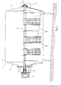
- Fig. 1 schematically shows, largely in vertical longitudinal section, an example of a holder 1 in which the invention can be used.
- the holder is a curd preparation vat, also called cheese vat or curd tank.
- the curd tank comprises a substantially horizontal cylindrical tank 2 with end shields 3 and 4. Extending within the tank in the longitudinal direction is a central shaft 5 which carries curd cutting and stirring members 6 and which is operatively driven for rotation by a driving motor 7.
- Such tanks are typically set up at a slight inclination to simplify emptying of the tank.
- the central shaft is bearing-mounted outside the tank 2 in a bearing construction 8 on the non-driven side, and on the driven side is connected through a coupling construction 9 with the driving motor 7, which at the same time functions as bearing.
- the central shaft 5 has a considerable length, which can be, for instance, in the order of 5 m.
- the central shaft is usually largely solid, that is, designed as a very thick-walled tube.
- the diameter of the shaft can be in the order of, for instance, 10 to 12 cm.
- Such a shaft bends to some extent under its own weight and as a result of the load occurring during operation, which must be taken up adjacent the bearing constructions through a possibility of allowing play.
- the sealing action of the sealing construction should be preserved.
- the holder itself typically having a wall thickness in the order of a few millimeters, for instance 3 mm, expands faster than the central shaft.
- the sealing construction on the side of the outer bearing 8 can shift relative to the central shaft in case of a large tank over a relatively large distance, which can for instance be in the order of 5 mm. This effect should also influence the sealing action to the least possible extent.
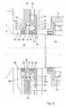
- Fig. 2 shows the portion II of Fig. 1 on a larger scale.
- the central shaft 5 passes from the interior of the tank by way of a reduced journal 10 through a wide opening 11 in the end shield 3 of the tank 2, and through a sealing construction 13, mounted on the end shield 3 via a supporting ring 12, to outside the tank.
- an external bearing construction 8 is mounted, remote from the sealing construction, on the supporting ring 12.
- the bearing construction 8 comprises a bearing house 14 which, in this example, includes a ball bearing 15 which, in this example, receives the slightly further reduced end part 16 of the journal 10.
- the bearing house 14 is connected through a number of radially distributed arms 17, one of which is visible, to a mounting ring 18, which in turn is attached to the supporting ring 12 with bolts 19.
- FIGs. 2 and 3 show the sealing construction at the non-driven end of the central shaft.
- a sealing construction according to the invention can also be used at the other end of the shaft.
- FIG. 2 The example of a sealing construction according to the invention shown in Fig. 2 is shown schematically on a slightly larger scale in Fig. 3.
- the sealing construction in the example shown comprises, viewed in axial direction and with respect to the interior of the tank, an inner sealing ring 20 and a similarly shaped outer sealing ring 21, both fitted on the journal 10.
- the sealing rings are made of suitable elastic material and in this example have an annular body 22 of a substantially rectangular cross section and having an axially outer surface 40, an axially inner surface 41, a radially outer surface 42 and a radially inner surface 43. See also Fig. 4, which schematically shows a cross section of an example of a sealing ring according to the invention on a still slightly larger scale.
- the annular body 22 forms directly a sealing with respect to the journal 10.
- the annular body is provided with a sealing lip 23, which extends obliquely upwards and in mounted condition outwards from the annular body, more specifically, from a both radially and axially outer edge of the annular body.
- the sealing lip 23 extends in line with a diagonal of the annular body, that is, from the transition area between the surfaces 40 and 42 in Fig. 4.
- the sealing lips 23 of sealing rings 20, 21 form a sealing edge 24, which operatively forms a sealing relative to a radial surface of the sealing construction.
- suitable materials for the sealing rings are rubber or rubbery materials, such as for instance food-approved FPM polymers, or EPDM and like materials.
- the sealing construction furthermore comprises a disc-shaped house 25, which is provided with positioning means to fix the sealing rings.
- the disc-shaped house is mounted on the supporting ring 12 with bolts 19a or the like, with interposition of sealing means such as an O-ring 26.
- the disc-shaped house 25 is provided with a central disc-shaped recess, in which a ring 27 is mounted.
- the ring 27 abuts by its surface facing the interior of the tank, with interposition of a first O-ring 28a, against a radial flange 29 of the disc-shaped house 25.
- the ring 27 further abuts by its axially outwardly facing surface, with interposition of a second O-ring 28b, against an annular member 30, which forms a central chamber 31 around the journal 10.
- the central chamber 31 is connected via at least one bore 32 in the annular member 30 with at least one supply line 33 for cleaning liquid.
- the central chamber 31 is furthermore connected via at least one other bore 34 with at least one drain line 35 for leakage fluid and cleaning liquid. It is also possible, however, to use one or more combined supply/drain lines.
- the outer sealing ring 21 is situated in the chamber 31, furthermore.
- the outer wall 36 of the chamber 31 is provided with cams 38 extending axially inwards under the sealing lip 23 of the outer sealing ring 21, which cams 38 abut against the axially outer surface 40 of the annular body 22 of the sealing ring 21.
- cams 38 also an annular shoulder with cross grooves or the like could be used.
- the outer sealing ring 21 furthermore abuts by its axially inner surface 41 against the axially outer surface 50 of the ring 27.
- the ring 27, further, is provided, in its axially outer surface 50 adjacent the sealing ring 21, with radially distributed recesses 51, which form a passage for cleaning liquid.
- the sealing lip 23 of the inner sealing ring 20 then abuts by its sealing edge 24 against the surface 52 of the ring 27.
- the axially inner surface 41 of the inner sealing ring 20 abuts against radially distributed fingers 54 of the disc-shaped house 25.
- the annular bodies of the sealing rings 20 and 21 are directly fixed relative to the end shield 3 of the tank. If the journal 10 and the tank wall move relative to each other in axial direction, the sealing rings remain in the same position relative to the tank wall, and the radially inner surfaces 43 of the sealing rings slide over the journal without the sealing lips 23 thereby being loaded or changing their orientation. The sealing action of the sealing lips 23 is therefore not influenced.
- the fingers 54, the ring 27 and the annular member 30 surround the journal 10 with some clearance "d", thereby allowing a slight radial movement of the journal 10 relative to the sealing construction.
- the sealing edges 24 of the sealing lips slide to some extent over the radial surfaces 37 and 52 of the chamber wall 36 and the ring 27, while the original orientation of the sealing lips is substantially preserved and the sealing action remains guaranteed.
- cleaning liquid is supplied under pressure via the supply line 33 for cleaning liquid and the bore 32 to the chamber 31.
- This cleaning liquid cannot pass the lip 23 of the outer sealing ring 21, but via the recesses 51 in the ring 27 and via the space between the ring 27 and the journal 10 and via the intermediate space between the cams 53, can reach the space 55 under the sealing lip 23 of the inner sealing ring.
- the lip 23 can bend upwards under the influence of the pressure exerted by the cleaning liquid, allowing the cleaning liquid to pass, whereby the space under the lip is cleaned.
- the sealing construction described can be designed with a sealing ring according to the invention in one receiving space and a different type of sealing ring in the other receiving space.
- the sealing construction can be designed with just a single receiving space for a sealing ring. In that case, in the example shown, for instance the outer receiving space situated between the ring 27 and the chamber wall 36, and the sealing ring 21 could be omitted.
- the ring 27 could then be attached by means of bolts or the like to the disc-shaped house 25.
- the sealing would then be provided by the sealing ring 20 situated in the receiving space 31a formed between the axially inner surface of the ring 27 and the fingers 54.
- Such a singular seal could for instance be used in a curd tank for making flat cheese, or in a curd distribution tank for block formers or in a mixing tank for curd and cream.
- a sealing ring according to the invention it would be possible to design the sealing construction with more than two axially consecutive receiving spaces for sealing rings, with a sealing ring according to the invention being used in at least one receiving space.
Landscapes
- Engineering & Computer Science (AREA)
- General Engineering & Computer Science (AREA)
- Mechanical Engineering (AREA)
- Sealing Devices (AREA)
- Sealing With Elastic Sealing Lips (AREA)
- Materials For Medical Uses (AREA)
- Sealing Battery Cases Or Jackets (AREA)
- Glass Compositions (AREA)
- Gasket Seals (AREA)
- Closures For Containers (AREA)
- Sealing Material Composition (AREA)
Claims (12)
- Käsebruchherstellwanne, die einen Halter (1) aufweist mit einer Halterwand (2,3,4), einer zentralen Welle (5,10), die Schneid- und/oder Rührelemente (6) trägt und die benachbart zu mindestens einem Ende durch die Halterwand (2,3,4) verläuft, wobei die Käsebruchzubereitungswanne mindestens eine Dichtungsanordnung (13) für die durch die Halterwand (2,3,4) laufende Welle (5,10) aufweist, wobei die Dichtungsanordnung (13) bei Betrieb mindestens einen Aufnahmeraum (31) und einen Dichtring (20,21) aufweist, wobei der Dichtring (20,21) einen ringförmigen Körper (22) aufweist, der abdichtend an der Welle (5,10) angebracht ist und der mit einer Dichtlippe (23) versehen ist, die mit einer Fläche (37;52) der Dichtungsanordnung (13) zusammenwirkt, wobei die Fläche relativ zu der Halterwand (2,3,4) stationär ist und radial relativ zu der Welle (5,10) verläuft, und wobei der ringförmige Körper (22) ferner eine axiale Innenfläche (41) aufweist, die an ersten Positioniereinrichtungen (27;54) der Dichtungsanordnung (13) anliegt, wobei die ersten Positioniereinrichtungen relativ zu der Halterwand stationär sind,
dadurch gekennzeichnet, dass
die Dichtlippe (23) des Dichtrings (20,21) sowohl radial als auch axial sowohl von einem radialen als auch von einem axialen Außenrandbereich des ringförmigen Körpers (22) schräg an außen verläuft, und sich zwischen der Dichtlippe (23) und der radialen Innenfläche (43) des ringförmigen Körpers (22), welche an der Welle (5,10) anliegt, eine axiale Außenfläche (40) des ringförmigen Körpers (22) befindet, die zum Fixieren des Dichtrings (20,21) zwischen den ersten (27;54) und zweiten (38;58) Positioniereinrichtungen direkt mit zweiten Positioniereinrichtungen (38;53) zusammenwirkt, welche relativ zu der Halterwand stationär sind und bei denen die Lippe (23) frei bleibt. - Käsebruchherstellwanne nach Anspruch 1, dadurch gekennzeichnet, dass die zweiten Positioniereinrichtungen (38;53) Nocken aufweisen, die benachbart zu der Welle von der Fläche (37;52) vorstehen, welche relativ zu der Welle (5,10) radial zu der axialen Außenfläche (40) des ringförmigen Körpers (22) verläuft.
- Käsebruchherstellwanne nach Anspruch 1 oder 2, dadurch gekennzeichnet, dass die ersten Positioniereinrichtungen (27;54) eine Anzahl von radialen Armen (54) aufweisen, die von von der Welle (5,10) beabstandeten Positionen in radialer Richtung zu einer Stelle nahe der Welle verlaufen.
- Käsebruchherstellwanne nach Anspruch 1, 2 oder 3, bei der die Dichtungsanordnung (13) einen axialen inneren (31a) und äußeren (31) Aufnahmeraum und mit diesem in Wirkverbindung stehend darin angeordnet jeweils einen inneren (20) und einen äußeren (21) Dichtring, die die Welle (5,10) umgeben, aufweist, wobei mindestens der innere Dichtring (20) eine Dichtlippe (23) nach Anspruch 1 aufweist, gekennzeichnet durch ein scheibenförmiges Gehäuse (25), das in Wirkverbindung mit der Halterwand (2,3,4) stehend mit dieser verbunden ist und einen zentralen Durchgang für die Welle (5,10) und eine zentrale Kammer aufweist, in der ein die Welle (5,10) umgebender Ring (27) platziert ist, welcher eine axiale Außenfläche (50) und eine axiale Innenfläche (52) aufweist, wobei die axiale Außenfläche (50) des Rings (27) an der axialen Innenfläche (41) des äußeren Dichtrings (21) anliegt, und wobei die zweiten Positioniereinrichtungen radial verteilte Nocken (53) an der axialen Innenfläche (52) des Rings (27) aufweisen, wobei die Nocken (53) an der axialen Außenfläche (40) des inneren Dichtrings (20) anliegen, während die Dichtlippe (23) des inneren Dichtrings (20) in einer radial jenseits der Nocken (53) liegenden Position an der axialen Innenfläche (52) des Rings (27) anliegt.
- Käsebruchherstellwanne nach Anspruch 4, dadurch gekennzeichnet, dass die ersten Positioniereinrichtungen radial verteilte Finger (54) aufweisen, die an dem scheibenförmigen Gehäuse (25) angeordnet sind, die relativ zu dem Ring (27) axial innen angeordnet sind und die in Richtung der Welle (5,10) verlaufen, wobei die Finger (54) an der axialen Innenfläche (41) des inneren Dichtrings (20) anliegen und zusammen mit den Nocken (53) des Rings (27) den inneren Dichtring (20) fixieren.
- Käsebruchherstellwanne nach Anspruch 4 oder 5, bei der der äußere Dichtring (21) eine Dichtlippe (23) nach Anspruch 1 aufweist, dadurch gekennzeichnet, dass die Dichtlippe (23) des äußeren Dichtrings (21), die von der Welle (5,10) beabstandet ist, an der Innenfläche (37) einer die zentrale Kammer (31) verschließenden radialen Außenwand (36) eines ringförmigen Elements (30) anliegt, welches die Welle (5,10) umschließt, wobei die Innenfläche (37) ferner benachbart zu der Welle (5, 10) axial nach innen ragende Positioniereinrichtungen (38) aufweist, die Teil der zweiten Positioniereinrichtungen für den äußeren Dichtring (21) bilden und die zwischen der Lippe (23) und der Welle (5,10) an der axialen Außenfläche (40) des ringförmigen Körpers (22) des äußeren Dichtrings (21) anliegen und die zusammen mit der axialen Außenfläche (50) des Rings (27) in der zentralen Kammer den äußeren Dichtring (21) fixieren.
- Käsebruchherstellwanne nach Anspruch 6, dadurch gekennzeichnet, dass die nach innen ragenden Positioniereinrichtungen an der Innenfläche (37) der radialen Außenwand (36) Nocken (38) aufweisen.
- Käsebruchherstellwanne nach einem der Ansprüche 4 bis 7, dadurch gekennzeichnet, dass der in der zentralen Kammer platzierte Ring (27) die Welle (5,10) mit einem gewissen Spiel (d) umgibt und der Ring (27) Ausnehmungen (51) in der axialen Außenfläche (50) benachbart zu dem äußeren Dichtring (21) aufweist, wobei die Ausnehmungen (51) zusammen mit dem Spiel (d) zwischen dem Ring (27) und der Welle (5, 10) einen Flüssigkeitsdurchgang bildet, der die zentrale Kammer (31) mit dem Zwischenraum (55) zwischen der Welle (5,10) und der Dichtlippe (23) des inneren Dichtrings (20) verbindet.
- Käsebruchherstellwanne nach einem der Ansprüche 4 bis 8, dadurch gekennzeichnet, dass die zentrale Kammer (31) mit mindestens einer Ablassleitung (35) und mindestens einer Zuführleitung (33) für eine Reinigungsflüssigkeit verbunden ist.
- Käsebruchherstellwanne nach einem der Ansprüche 4 bis 9, dadurch gekennzeichnet, dass an der Außenseite des scheibenförmigen Gehäuses (25) eine Anzahl von Armen (17) angebracht ist, die eine Lagerstruktur (8) für die zentrale Welle (5,10) tragen und die in einem axialen Abstand zu der Dichtungsstruktur (13) angeordnet sind.
- Käsebruchherstellwanne nach einem der vorhergehenden Ansprüche, dadurch gekennzeichnet, dass die Käsebruchherstellwanne eine langgestreckte Wanne ist, die zum Aufstellen in horizontaler Position vorgesehen ist.
- Käsebruchherstellwanne nach einem der vorhergehenden Ansprüche, mit einer Welle (5,10), die eine große Länge in der Größenordnung von ungefähr 3 m oder mehr aufweist.
Priority Applications (1)
| Application Number | Priority Date | Filing Date | Title |
|---|---|---|---|
| PL05076760T PL1621804T3 (pl) | 2004-07-30 | 2005-07-29 | Konstrukcja uszczelniająca |
Applications Claiming Priority (1)
| Application Number | Priority Date | Filing Date | Title |
|---|---|---|---|
| NL1026756A NL1026756C2 (nl) | 2004-07-30 | 2004-07-30 | Afdichtconstructie. |
Publications (2)
| Publication Number | Publication Date |
|---|---|
| EP1621804A1 EP1621804A1 (de) | 2006-02-01 |
| EP1621804B1 true EP1621804B1 (de) | 2007-09-26 |
Family
ID=34974241
Family Applications (1)
| Application Number | Title | Priority Date | Filing Date |
|---|---|---|---|
| EP05076760A Expired - Lifetime EP1621804B1 (de) | 2004-07-30 | 2005-07-29 | Dichtungsanordnung |
Country Status (10)
| Country | Link |
|---|---|
| US (1) | US7544917B2 (de) |
| EP (1) | EP1621804B1 (de) |
| AT (1) | ATE374330T1 (de) |
| AU (1) | AU2005203362B2 (de) |
| CA (1) | CA2514008C (de) |
| DE (1) | DE602005002596T2 (de) |
| DK (1) | DK1621804T3 (de) |
| NL (1) | NL1026756C2 (de) |
| NZ (1) | NZ541574A (de) |
| PL (1) | PL1621804T3 (de) |
Families Citing this family (5)
| Publication number | Priority date | Publication date | Assignee | Title |
|---|---|---|---|---|
| WO2007132723A1 (ja) * | 2006-05-13 | 2007-11-22 | Yasunori Onozuka | 形状特化部を有する被浴体 |
| US20110254231A1 (en) * | 2010-04-19 | 2011-10-20 | Isenberg Timothy J | Clean-In-Place Seal Assembly |
| US9188163B2 (en) | 2010-04-19 | 2015-11-17 | Custom Fabricating & Repair, Inc. | Clean-in place shaft bushing |
| US8944277B2 (en) | 2010-04-19 | 2015-02-03 | Cheese & Whey Systems, Inc. | Food processing vat with a clean-in-place vent |
| US8979356B2 (en) | 2012-12-18 | 2015-03-17 | Feldmeier Equipment, Inc. | Dual agitator mixer with sanitary tank |
Family Cites Families (11)
| Publication number | Priority date | Publication date | Assignee | Title |
|---|---|---|---|---|
| US3038733A (en) * | 1958-10-10 | 1962-06-12 | Chicago Rawhide Mfg Co | Gap seal |
| GB1025999A (en) * | 1964-03-09 | 1966-04-14 | Stensholms Fabriks Ab | Improvements in shaft oil seals |
| SE326082B (de) * | 1969-01-29 | 1970-07-13 | B Eriksson | |
| US3934311A (en) * | 1973-07-13 | 1976-01-27 | Thompson John W | Oyster breaker operated by electric motor having bearing seal device |
| US4071255A (en) * | 1976-10-12 | 1978-01-31 | Morgan Construction Company | Flexible seal element with reinforced drain labyrinth |
| SE404414B (sv) | 1977-02-25 | 1978-10-02 | Alfa Laval Ab | Anordning for att diska en forsta tetningsring och ett utrymme nermast intill tetningsringen |
| DE3700839A1 (de) * | 1987-01-14 | 1988-07-28 | Heinz Konrad Prof Dr I Mueller | Wellendichtung |
| JPH0722532Y2 (ja) * | 1988-06-14 | 1995-05-24 | エヌオーケー株式会社 | 密封装置 |
| US4989504A (en) * | 1988-11-09 | 1991-02-05 | Sherping Systems, Inc. | Food processing vat |
| US4973063A (en) * | 1989-07-14 | 1990-11-27 | Itt Corporation | Tandem mounted face seals |
| NL1015016C2 (nl) * | 2000-04-25 | 2001-10-26 | Tetra Laval Holdings & Finance | Inrichting voor het snijden en roeren van wrongel. |
-
2004
- 2004-07-30 NL NL1026756A patent/NL1026756C2/nl not_active IP Right Cessation
-
2005
- 2005-07-28 CA CA2514008A patent/CA2514008C/en not_active Expired - Fee Related
- 2005-07-29 EP EP05076760A patent/EP1621804B1/de not_active Expired - Lifetime
- 2005-07-29 AT AT05076760T patent/ATE374330T1/de not_active IP Right Cessation
- 2005-07-29 PL PL05076760T patent/PL1621804T3/pl unknown
- 2005-07-29 AU AU2005203362A patent/AU2005203362B2/en not_active Ceased
- 2005-07-29 US US11/192,931 patent/US7544917B2/en not_active Expired - Fee Related
- 2005-07-29 DE DE602005002596T patent/DE602005002596T2/de not_active Expired - Lifetime
- 2005-07-29 NZ NZ541574A patent/NZ541574A/en not_active IP Right Cessation
- 2005-07-29 DK DK05076760T patent/DK1621804T3/da active
Also Published As
| Publication number | Publication date |
|---|---|
| AU2005203362B2 (en) | 2008-02-28 |
| DE602005002596D1 (de) | 2007-11-08 |
| ATE374330T1 (de) | 2007-10-15 |
| CA2514008A1 (en) | 2006-01-30 |
| DK1621804T3 (da) | 2008-02-04 |
| US20060021518A1 (en) | 2006-02-02 |
| NZ541574A (en) | 2006-05-26 |
| EP1621804A1 (de) | 2006-02-01 |
| PL1621804T3 (pl) | 2008-04-30 |
| CA2514008C (en) | 2010-09-07 |
| US7544917B2 (en) | 2009-06-09 |
| AU2005203362A1 (en) | 2006-02-16 |
| DE602005002596T2 (de) | 2008-06-26 |
| NL1026756C2 (nl) | 2006-01-31 |
Similar Documents
| Publication | Publication Date | Title |
|---|---|---|
| EP4075002B1 (de) | Trägeranordnung für lebensmittelanwendungen mit einer verbesserten hinteren dichtungsvorrichtung | |
| CN109210087B (zh) | 用于滚动轴承的密封装置 | |
| US9708168B2 (en) | Rotary distributor for distributing free-flowing media | |
| EP4075003B1 (de) | Trägeranordnung für lebensmittelanwendungen, die eine verbesserte innere abdichtung aufweisen | |
| EP1621804B1 (de) | Dichtungsanordnung | |
| GB2235737A (en) | Mechanical seal unit | |
| SE515100C2 (sv) | Anordning för avtätning av en spalt | |
| US4473171A (en) | Nozzle construction for jacketed pressure vessels | |
| CN114251371A (zh) | 高排放轮毂单元 | |
| EP4299932A1 (de) | Stützanordnung für lebensmittelanwendungen | |
| US20080257417A1 (en) | Pipe Branching Arrangement | |
| CA2179544A1 (en) | Radially engageable leakproof coupling | |
| US12241505B2 (en) | Support assembly for food applications | |
| CN114981549B (zh) | 套筒、套筒的用途、轴承壳和轴承壳的用途 | |
| EP3916258B1 (de) | Deckel für ein lagergehäuse und trägeranordnung für eine zugehörige rotierende welle | |
| US20110114198A1 (en) | Device for installing piping in process plants in the food and beverage industry | |
| US12409398B2 (en) | Screen having variable circumference for a thermostatic valve | |
| EP4660472A1 (de) | Stützanordnung für lebensmittelanwendungen | |
| EP3581263B1 (de) | Rühreranordnung | |
| KR200165917Y1 (ko) | 전동식 사방향 절환 밸브 | |
| US12066108B2 (en) | Rotary seals | |
| EP3837456A1 (de) | Absperrvorrichtung zur abdichtung einer welle einer rotationsmaschine sowie rotationsmaschine | |
| Moerman | Hygienic Design of Closed Equipment for the Processing | |
| GB2109077A (en) | Pipe seal | |
| WO2002066751A1 (en) | Device for piping system |
Legal Events
| Date | Code | Title | Description |
|---|---|---|---|
| PUAI | Public reference made under article 153(3) epc to a published international application that has entered the european phase |
Free format text: ORIGINAL CODE: 0009012 |
|
| AK | Designated contracting states |
Kind code of ref document: A1 Designated state(s): AT BE BG CH CY CZ DE DK EE ES FI FR GB GR HU IE IS IT LI LT LU LV MC NL PL PT RO SE SI SK TR |
|
| AX | Request for extension of the european patent |
Extension state: AL BA HR MK YU |
|
| 17P | Request for examination filed |
Effective date: 20060502 |
|
| 17Q | First examination report despatched |
Effective date: 20060628 |
|
| AKX | Designation fees paid |
Designated state(s): AT BE BG CH CY CZ DE DK EE ES FI FR GB GR HU IE IS IT LI LT LU LV MC NL PL PT RO SE SI SK TR |
|
| GRAP | Despatch of communication of intention to grant a patent |
Free format text: ORIGINAL CODE: EPIDOSNIGR1 |
|
| GRAS | Grant fee paid |
Free format text: ORIGINAL CODE: EPIDOSNIGR3 |
|
| GRAA | (expected) grant |
Free format text: ORIGINAL CODE: 0009210 |
|
| AK | Designated contracting states |
Kind code of ref document: B1 Designated state(s): AT BE BG CH CY CZ DE DK EE ES FI FR GB GR HU IE IS IT LI LT LU LV MC NL PL PT RO SE SI SK TR |
|
| REG | Reference to a national code |
Ref country code: GB Ref legal event code: FG4D |
|
| REG | Reference to a national code |
Ref country code: CH Ref legal event code: EP |
|
| REF | Corresponds to: |
Ref document number: 602005002596 Country of ref document: DE Date of ref document: 20071108 Kind code of ref document: P |
|
| REG | Reference to a national code |
Ref country code: IE Ref legal event code: FG4D |
|
| PG25 | Lapsed in a contracting state [announced via postgrant information from national office to epo] |
Ref country code: LT Free format text: LAPSE BECAUSE OF FAILURE TO SUBMIT A TRANSLATION OF THE DESCRIPTION OR TO PAY THE FEE WITHIN THE PRESCRIBED TIME-LIMIT Effective date: 20070926 Ref country code: FI Free format text: LAPSE BECAUSE OF FAILURE TO SUBMIT A TRANSLATION OF THE DESCRIPTION OR TO PAY THE FEE WITHIN THE PRESCRIBED TIME-LIMIT Effective date: 20070926 |
|
| REG | Reference to a national code |
Ref country code: DK Ref legal event code: T3 |
|
| PG25 | Lapsed in a contracting state [announced via postgrant information from national office to epo] |
Ref country code: AT Free format text: LAPSE BECAUSE OF FAILURE TO SUBMIT A TRANSLATION OF THE DESCRIPTION OR TO PAY THE FEE WITHIN THE PRESCRIBED TIME-LIMIT Effective date: 20070926 |
|
| PG25 | Lapsed in a contracting state [announced via postgrant information from national office to epo] |
Ref country code: BE Free format text: LAPSE BECAUSE OF FAILURE TO SUBMIT A TRANSLATION OF THE DESCRIPTION OR TO PAY THE FEE WITHIN THE PRESCRIBED TIME-LIMIT Effective date: 20070926 Ref country code: LV Free format text: LAPSE BECAUSE OF FAILURE TO SUBMIT A TRANSLATION OF THE DESCRIPTION OR TO PAY THE FEE WITHIN THE PRESCRIBED TIME-LIMIT Effective date: 20070926 |
|
| REG | Reference to a national code |
Ref country code: CH Ref legal event code: PL |
|
| PG25 | Lapsed in a contracting state [announced via postgrant information from national office to epo] |
Ref country code: GR Free format text: LAPSE BECAUSE OF FAILURE TO SUBMIT A TRANSLATION OF THE DESCRIPTION OR TO PAY THE FEE WITHIN THE PRESCRIBED TIME-LIMIT Effective date: 20071227 Ref country code: ES Free format text: LAPSE BECAUSE OF FAILURE TO SUBMIT A TRANSLATION OF THE DESCRIPTION OR TO PAY THE FEE WITHIN THE PRESCRIBED TIME-LIMIT Effective date: 20080106 Ref country code: CH Free format text: LAPSE BECAUSE OF FAILURE TO SUBMIT A TRANSLATION OF THE DESCRIPTION OR TO PAY THE FEE WITHIN THE PRESCRIBED TIME-LIMIT Effective date: 20070926 Ref country code: LI Free format text: LAPSE BECAUSE OF FAILURE TO SUBMIT A TRANSLATION OF THE DESCRIPTION OR TO PAY THE FEE WITHIN THE PRESCRIBED TIME-LIMIT Effective date: 20070926 |
|
| REG | Reference to a national code |
Ref country code: PL Ref legal event code: T3 |
|
| PG25 | Lapsed in a contracting state [announced via postgrant information from national office to epo] |
Ref country code: PT Free format text: LAPSE BECAUSE OF FAILURE TO SUBMIT A TRANSLATION OF THE DESCRIPTION OR TO PAY THE FEE WITHIN THE PRESCRIBED TIME-LIMIT Effective date: 20080226 Ref country code: SK Free format text: LAPSE BECAUSE OF FAILURE TO SUBMIT A TRANSLATION OF THE DESCRIPTION OR TO PAY THE FEE WITHIN THE PRESCRIBED TIME-LIMIT Effective date: 20070926 Ref country code: IS Free format text: LAPSE BECAUSE OF FAILURE TO SUBMIT A TRANSLATION OF THE DESCRIPTION OR TO PAY THE FEE WITHIN THE PRESCRIBED TIME-LIMIT Effective date: 20080126 Ref country code: CZ Free format text: LAPSE BECAUSE OF FAILURE TO SUBMIT A TRANSLATION OF THE DESCRIPTION OR TO PAY THE FEE WITHIN THE PRESCRIBED TIME-LIMIT Effective date: 20070926 |
|
| PG25 | Lapsed in a contracting state [announced via postgrant information from national office to epo] |
Ref country code: SE Free format text: LAPSE BECAUSE OF FAILURE TO SUBMIT A TRANSLATION OF THE DESCRIPTION OR TO PAY THE FEE WITHIN THE PRESCRIBED TIME-LIMIT Effective date: 20071226 Ref country code: RO Free format text: LAPSE BECAUSE OF FAILURE TO SUBMIT A TRANSLATION OF THE DESCRIPTION OR TO PAY THE FEE WITHIN THE PRESCRIBED TIME-LIMIT Effective date: 20070926 |
|
| EN | Fr: translation not filed | ||
| PLBE | No opposition filed within time limit |
Free format text: ORIGINAL CODE: 0009261 |
|
| STAA | Information on the status of an ep patent application or granted ep patent |
Free format text: STATUS: NO OPPOSITION FILED WITHIN TIME LIMIT |
|
| 26N | No opposition filed |
Effective date: 20080627 |
|
| PG25 | Lapsed in a contracting state [announced via postgrant information from national office to epo] |
Ref country code: FR Free format text: LAPSE BECAUSE OF FAILURE TO SUBMIT A TRANSLATION OF THE DESCRIPTION OR TO PAY THE FEE WITHIN THE PRESCRIBED TIME-LIMIT Effective date: 20080704 |
|
| PG25 | Lapsed in a contracting state [announced via postgrant information from national office to epo] |
Ref country code: MC Free format text: LAPSE BECAUSE OF NON-PAYMENT OF DUE FEES Effective date: 20080731 |
|
| PG25 | Lapsed in a contracting state [announced via postgrant information from national office to epo] |
Ref country code: EE Free format text: LAPSE BECAUSE OF FAILURE TO SUBMIT A TRANSLATION OF THE DESCRIPTION OR TO PAY THE FEE WITHIN THE PRESCRIBED TIME-LIMIT Effective date: 20070926 |
|
| PG25 | Lapsed in a contracting state [announced via postgrant information from national office to epo] |
Ref country code: SI Free format text: LAPSE BECAUSE OF FAILURE TO SUBMIT A TRANSLATION OF THE DESCRIPTION OR TO PAY THE FEE WITHIN THE PRESCRIBED TIME-LIMIT Effective date: 20070926 |
|
| PG25 | Lapsed in a contracting state [announced via postgrant information from national office to epo] |
Ref country code: CY Free format text: LAPSE BECAUSE OF FAILURE TO SUBMIT A TRANSLATION OF THE DESCRIPTION OR TO PAY THE FEE WITHIN THE PRESCRIBED TIME-LIMIT Effective date: 20070926 Ref country code: IE Free format text: LAPSE BECAUSE OF NON-PAYMENT OF DUE FEES Effective date: 20080729 |
|
| PG25 | Lapsed in a contracting state [announced via postgrant information from national office to epo] |
Ref country code: BG Free format text: LAPSE BECAUSE OF FAILURE TO SUBMIT A TRANSLATION OF THE DESCRIPTION OR TO PAY THE FEE WITHIN THE PRESCRIBED TIME-LIMIT Effective date: 20071226 |
|
| PG25 | Lapsed in a contracting state [announced via postgrant information from national office to epo] |
Ref country code: LU Free format text: LAPSE BECAUSE OF NON-PAYMENT OF DUE FEES Effective date: 20080729 Ref country code: HU Free format text: LAPSE BECAUSE OF FAILURE TO SUBMIT A TRANSLATION OF THE DESCRIPTION OR TO PAY THE FEE WITHIN THE PRESCRIBED TIME-LIMIT Effective date: 20080327 |
|
| PG25 | Lapsed in a contracting state [announced via postgrant information from national office to epo] |
Ref country code: TR Free format text: LAPSE BECAUSE OF FAILURE TO SUBMIT A TRANSLATION OF THE DESCRIPTION OR TO PAY THE FEE WITHIN THE PRESCRIBED TIME-LIMIT Effective date: 20070926 |
|
| PG25 | Lapsed in a contracting state [announced via postgrant information from national office to epo] |
Ref country code: IT Free format text: LAPSE BECAUSE OF NON-PAYMENT OF DUE FEES Effective date: 20080731 |
|
| PGFP | Annual fee paid to national office [announced via postgrant information from national office to epo] |
Ref country code: PL Payment date: 20180604 Year of fee payment: 14 |
|
| PGFP | Annual fee paid to national office [announced via postgrant information from national office to epo] |
Ref country code: DE Payment date: 20180717 Year of fee payment: 14 Ref country code: NL Payment date: 20180712 Year of fee payment: 14 |
|
| PGFP | Annual fee paid to national office [announced via postgrant information from national office to epo] |
Ref country code: DK Payment date: 20180711 Year of fee payment: 14 Ref country code: GB Payment date: 20180725 Year of fee payment: 14 |
|
| REG | Reference to a national code |
Ref country code: DE Ref legal event code: R119 Ref document number: 602005002596 Country of ref document: DE |
|
| REG | Reference to a national code |
Ref country code: DK Ref legal event code: EBP Effective date: 20190731 |
|
| GBPC | Gb: european patent ceased through non-payment of renewal fee |
Effective date: 20190729 |
|
| PG25 | Lapsed in a contracting state [announced via postgrant information from national office to epo] |
Ref country code: DE Free format text: LAPSE BECAUSE OF NON-PAYMENT OF DUE FEES Effective date: 20200201 Ref country code: GB Free format text: LAPSE BECAUSE OF NON-PAYMENT OF DUE FEES Effective date: 20190729 Ref country code: NL Free format text: LAPSE BECAUSE OF NON-PAYMENT OF DUE FEES Effective date: 20190801 |
|
| REG | Reference to a national code |
Ref country code: NL Ref legal event code: MM Effective date: 20190801 |
|
| PG25 | Lapsed in a contracting state [announced via postgrant information from national office to epo] |
Ref country code: DK Free format text: LAPSE BECAUSE OF NON-PAYMENT OF DUE FEES Effective date: 20190731 |
|
| PG25 | Lapsed in a contracting state [announced via postgrant information from national office to epo] |
Ref country code: PL Free format text: LAPSE BECAUSE OF NON-PAYMENT OF DUE FEES Effective date: 20190729 |