EP1621806A1 - Ventil für das Bereinigen der Luft in der Füllung und in der Aufnahme davon während des Leerens der unter Druck gesetzten Flüssigkeit von den Durchflusskanälen - Google Patents
Ventil für das Bereinigen der Luft in der Füllung und in der Aufnahme davon während des Leerens der unter Druck gesetzten Flüssigkeit von den Durchflusskanälen Download PDFInfo
- Publication number
- EP1621806A1 EP1621806A1 EP05380146A EP05380146A EP1621806A1 EP 1621806 A1 EP1621806 A1 EP 1621806A1 EP 05380146 A EP05380146 A EP 05380146A EP 05380146 A EP05380146 A EP 05380146A EP 1621806 A1 EP1621806 A1 EP 1621806A1
- Authority
- EP
- European Patent Office
- Prior art keywords
- float
- valve
- air
- emptying
- admission
- Prior art date
- Legal status (The legal status is an assumption and is not a legal conclusion. Google has not performed a legal analysis and makes no representation as to the accuracy of the status listed.)
- Granted
Links
Images
Classifications
-
- F—MECHANICAL ENGINEERING; LIGHTING; HEATING; WEAPONS; BLASTING
- F16—ENGINEERING ELEMENTS AND UNITS; GENERAL MEASURES FOR PRODUCING AND MAINTAINING EFFECTIVE FUNCTIONING OF MACHINES OR INSTALLATIONS; THERMAL INSULATION IN GENERAL
- F16K—VALVES; TAPS; COCKS; ACTUATING-FLOATS; DEVICES FOR VENTING OR AERATING
- F16K17/00—Safety valves; Equalising valves, e.g. pressure relief valves
- F16K17/20—Excess-flow valves
- F16K17/22—Excess-flow valves actuated by the difference of pressure between two places in the flow line
- F16K17/24—Excess-flow valves actuated by the difference of pressure between two places in the flow line acting directly on the cutting-off member
-
- F—MECHANICAL ENGINEERING; LIGHTING; HEATING; WEAPONS; BLASTING
- F16—ENGINEERING ELEMENTS AND UNITS; GENERAL MEASURES FOR PRODUCING AND MAINTAINING EFFECTIVE FUNCTIONING OF MACHINES OR INSTALLATIONS; THERMAL INSULATION IN GENERAL
- F16K—VALVES; TAPS; COCKS; ACTUATING-FLOATS; DEVICES FOR VENTING OR AERATING
- F16K24/00—Devices, e.g. valves, for venting or aerating enclosures
- F16K24/04—Devices, e.g. valves, for venting or aerating enclosures for venting only
- F16K24/042—Devices, e.g. valves, for venting or aerating enclosures for venting only actuated by a float
- F16K24/044—Devices, e.g. valves, for venting or aerating enclosures for venting only actuated by a float the float being rigidly connected to the valve element, the assembly of float and valve element following a substantially translational movement when actuated, e.g. also for actuating a pilot valve
Definitions
- the present invention refers to a valve for purging air in the filling and admission thereof during the emptying of pressurized liquid flow ducts, which has a float system and a membrane connected to each other in order to permit the removal of air accumulated and/or produced in pressurized liquid flow ducts, permitting in the case of a reduction of pressure the intake of air, so that adequate performance of certain ducting parts, such as filters, etc., is achieved.
- the purpose of the invention is to provide the corresponding sector in particular and the public in general, with a valve of the above-cited type, but with some particular characteristics from which greater structural simplicity of the valve, more efficient operation, and, in turn, some better performance qualities with respect to other valves having the same function are derived.
- valves that are assembled in pressurized water or liquid flow ducts are known. Their purpose is to eliminate small amounts of air that are accumulated or produced in the ducts themselves. In some cases, these valves are made in such a way that they also permit the outflow of large amounts of air.
- valve described in said European patent is designed to remove small amounts of air as well as large amounts of air that is normally carried out by independent valves, called “automatic valve” in the first case and “kinetic valve” in the second case.
- valve object of the invention has some basic characteristics like the ones cited in the preceding section, but with a series of innovations from which structural and functional advantages with respect to the type of valves described in the European patents alluded to before are derived.
- the valve in question is comprised, since it is a conventional valve, of a hollow body defined by the coupling by means of threading of two parts, one of which is provided with a coupling for the fluid intake.
- a float Inside the hollow body, there is a float connected to a flexible membrane which in a normal position presses, by thrust of the fluid on the float, against a valve seat, closing the air outlet, whereas when air is produced the float moves in the opposite direction by the effect of the difference of density, separating the membrane from the whole or from the seat thereof, allowing the outflow of air.
- a first novel characteristic of the valve of the invention is centered on the fact that the air outlet is a single grooved-form hole, through which air comes out in small amounts or the air comes out in large amounts, with the particularity that this outlet extends outside on a neck with an inside thread in order to permit the coupling of other outside devices, for example, for the ducting of possible leaks of liquid during normal operation of the valve.
- the membrane should be assembled obliquely, specifically on a chamfered surface of the float, a surface, which is defined as a side top surface.
- protrusions and projections define a means for optimum positioning of the membrane, as well as efficient operation thereof.
- the cited flexible membrane has one of its edges cylindrically thickened for tight coupling and by sliding in the top channel (as one can see in the attached drawings) established for this purpose in the top end area of the side top part of the float, all in such a way that the valve fastened by the top end will carry out the function of removing air when the duct is pressurized or will allow the intake of air when the duct is depressurized in order to prevent the collapsing of the parts. In this way, it carries out a function of protecting the installation.
- valve lies on the shape of the float, which is formed by an elongated body with an aerodynamic design.
- the body of the valve occupies a large part of the hollow.
- the cited float has some guiding means for the coupling or correct assembly thereof inside the valve body.
- the guiding means are comprised of (male) protrusions complementary of the (female) channels provided for this purpose on the inside side surface of the part of the valve body, which prevents the float from being incorrectly put in place.
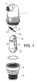
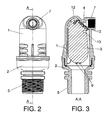
- valve of the invention is formed by the coupling between two parts (1) and (2), defining a hollow body inside of which a float (3) is assembled.
- a flexible membrane (4) is assembled on the float, in such a way that the part (2) has a threaded extension (5) defining a coupling means for the intake of fluid into the general body of the valve.
- a hole (6) is defined, according to an oblique arrangement, for the removal of air.
- the valve body has an outside extension defining a neck (7) with an inside thread in order to couple devices, for example, for collecting water that might be expelled with the air, etc.
- the float (3) has side protrusions (8) that in the assembly thereof inside the valve body are guided in channels (9) established for this purpose on the inside surface of the part (1) corresponding to the valve body.
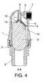
- the flexible membrane (4) As to the flexible membrane (4), it has some protrusions (10) and some projections (11) in order to rest on the side top part of the float (3), defining an effective, simple and optimum means for positioning and assembling said flexible membrane (4) on the float (3), just as it is represented in figures 3 and 4. Besides there is the particularity that the cited membrane (4) has in one of its opposite edges a cylindrical thickening (12) used to house, in a complementary cavity (13) formed for this purpose in the corresponding part of the float (3). Hence, the flexible membrane (4) remains perfectly fastened to the float (3).
Landscapes
- Engineering & Computer Science (AREA)
- General Engineering & Computer Science (AREA)
- Mechanical Engineering (AREA)
- Self-Closing Valves And Venting Or Aerating Valves (AREA)
- Filling Or Discharging Of Gas Storage Vessels (AREA)
- Respiratory Apparatuses And Protective Means (AREA)
- Filling Of Jars Or Cans And Processes For Cleaning And Sealing Jars (AREA)
Priority Applications (1)
| Application Number | Priority Date | Filing Date | Title |
|---|---|---|---|
| PL05380146T PL1621806T3 (pl) | 2004-07-28 | 2005-07-01 | Zawór do odpowietrzania przy napełnianiu i napowietrzania przy opróżnianiu przewodów przepływowych z cieczą pod ciśnieniem |
Applications Claiming Priority (1)
| Application Number | Priority Date | Filing Date | Title |
|---|---|---|---|
| ES200401834U ES1058143Y (es) | 2004-07-28 | 2004-07-28 | Valvula para la purga de aire en la operacion de llenado y admision del mismo durante el vaciado de conductos de circulacion de liquidos a presion |
Publications (2)
| Publication Number | Publication Date |
|---|---|
| EP1621806A1 true EP1621806A1 (de) | 2006-02-01 |
| EP1621806B1 EP1621806B1 (de) | 2007-08-22 |
Family
ID=33396416
Family Applications (1)
| Application Number | Title | Priority Date | Filing Date |
|---|---|---|---|
| EP05380146A Expired - Lifetime EP1621806B1 (de) | 2004-07-28 | 2005-07-01 | Ventil für das Bereinigen der Luft in der Füllung und in der Aufnahme davon während des Leerens der unter Druck gesetzten Flüssigkeit von den Durchflusskanälen |
Country Status (6)
| Country | Link |
|---|---|
| EP (1) | EP1621806B1 (de) |
| AT (1) | ATE371133T1 (de) |
| DE (1) | DE602005002095D1 (de) |
| ES (2) | ES1058143Y (de) |
| PL (1) | PL1621806T3 (de) |
| PT (1) | PT1621806E (de) |
Cited By (1)
| Publication number | Priority date | Publication date | Assignee | Title |
|---|---|---|---|---|
| CN117469509A (zh) * | 2023-10-16 | 2024-01-30 | 南京云之璟机电科技有限公司 | 自动排气装置及其应用 |
Families Citing this family (1)
| Publication number | Priority date | Publication date | Assignee | Title |
|---|---|---|---|---|
| CN114423979B (zh) | 2019-09-24 | 2025-02-25 | 艾瑞流体控制设备有限公司 | 具有低压密封的空气释放阀 |
Citations (5)
| Publication number | Priority date | Publication date | Assignee | Title |
|---|---|---|---|---|
| EP0257811A2 (de) | 1986-08-01 | 1988-03-02 | Aran Engineering Development Ltd | Durchflussventil |
| EP0724098A1 (de) | 1995-01-25 | 1996-07-31 | Raviv Precision Injection Molding | Überrollentlüftungsventil |
| DE29620494U1 (de) * | 1996-11-25 | 1998-03-26 | Spanner-Pollux Gmbh, 67063 Ludwigshafen | Vorrichtung zum Entlüften von Trinkwasser-Versorgungsleitungen |
| US6145533A (en) * | 1997-03-31 | 2000-11-14 | Nelson Irrigation Corporation | Air release valve |
| EP1124083A2 (de) * | 2000-02-09 | 2001-08-16 | Eaton Corporation | Entlüftungsventil für einen Kraftstofftank |
-
2004
- 2004-07-28 ES ES200401834U patent/ES1058143Y/es not_active Expired - Fee Related
-
2005
- 2005-07-01 DE DE602005002095T patent/DE602005002095D1/de not_active Expired - Lifetime
- 2005-07-01 PL PL05380146T patent/PL1621806T3/pl unknown
- 2005-07-01 AT AT05380146T patent/ATE371133T1/de not_active IP Right Cessation
- 2005-07-01 EP EP05380146A patent/EP1621806B1/de not_active Expired - Lifetime
- 2005-07-01 PT PT05380146T patent/PT1621806E/pt unknown
- 2005-07-01 ES ES05380146T patent/ES2293515T3/es not_active Expired - Lifetime
Patent Citations (5)
| Publication number | Priority date | Publication date | Assignee | Title |
|---|---|---|---|---|
| EP0257811A2 (de) | 1986-08-01 | 1988-03-02 | Aran Engineering Development Ltd | Durchflussventil |
| EP0724098A1 (de) | 1995-01-25 | 1996-07-31 | Raviv Precision Injection Molding | Überrollentlüftungsventil |
| DE29620494U1 (de) * | 1996-11-25 | 1998-03-26 | Spanner-Pollux Gmbh, 67063 Ludwigshafen | Vorrichtung zum Entlüften von Trinkwasser-Versorgungsleitungen |
| US6145533A (en) * | 1997-03-31 | 2000-11-14 | Nelson Irrigation Corporation | Air release valve |
| EP1124083A2 (de) * | 2000-02-09 | 2001-08-16 | Eaton Corporation | Entlüftungsventil für einen Kraftstofftank |
Cited By (1)
| Publication number | Priority date | Publication date | Assignee | Title |
|---|---|---|---|---|
| CN117469509A (zh) * | 2023-10-16 | 2024-01-30 | 南京云之璟机电科技有限公司 | 自动排气装置及其应用 |
Also Published As
| Publication number | Publication date |
|---|---|
| PT1621806E (pt) | 2007-11-29 |
| PL1621806T3 (pl) | 2008-04-30 |
| ES2293515T3 (es) | 2008-03-16 |
| ES1058143Y (es) | 2005-02-16 |
| ATE371133T1 (de) | 2007-09-15 |
| DE602005002095D1 (de) | 2007-10-04 |
| ES1058143U (es) | 2004-11-01 |
| EP1621806B1 (de) | 2007-08-22 |
Similar Documents
| Publication | Publication Date | Title |
|---|---|---|
| US7950621B2 (en) | Pneumatic pressure regulation valve | |
| CN109222838B (zh) | 一种用于洗碗机的多功能呼吸器及其洗碗机 | |
| MXPA97006624A (en) | A gas valve for surging a pulse of | |
| JP2008286190A (ja) | 内燃機関のクランクケースベンチレーション用のバルブ及びシリンダヘッドカバー | |
| CA2962521A1 (en) | Non-return valve for flue gas venting and damper assembly for use therein | |
| CN105840893A (zh) | 自动压力排放阀 | |
| EP1724402A1 (de) | Selbstabdichtender bodenablauf | |
| US20170218610A1 (en) | Air admittance valve | |
| EP1621806B1 (de) | Ventil für das Bereinigen der Luft in der Füllung und in der Aufnahme davon während des Leerens der unter Druck gesetzten Flüssigkeit von den Durchflusskanälen | |
| CN208397378U (zh) | 一种减压阀 | |
| EP3299202B1 (de) | Kraftstoffdampf-ventilsystem und komponenten dafür | |
| CN212338312U (zh) | 弹性片调压结构及液压系统气压调节装置 | |
| CN218955202U (zh) | 一种冷凝水收集装置及其燃气采暖热水炉 | |
| CN115950088B (zh) | 接水盘及除湿机 | |
| CN108843885B (zh) | 排气阀 | |
| CN115523664B (zh) | 一种冷凝水收集装置及其燃气采暖热水炉 | |
| CN218644370U (zh) | 用于中冷器的排水阀和具有其的中冷器 | |
| CN222880289U (zh) | 通气塞以及车辆 | |
| CN212656332U (zh) | 膜片式阻隔器 | |
| CN213711888U (zh) | 一种燃气调压阀 | |
| CN106438138A (zh) | 舷外机的电喷燃油系统 | |
| JPH09329271A (ja) | ポンプ装置のフロート弁 | |
| WO2001038764A1 (en) | Combination air release valve | |
| KR20200058789A (ko) | 내연기관용 조립식 pcv 밸브장치 | |
| KR200463373Y1 (ko) | 자동 개폐 밸브 |
Legal Events
| Date | Code | Title | Description |
|---|---|---|---|
| PUAI | Public reference made under article 153(3) epc to a published international application that has entered the european phase |
Free format text: ORIGINAL CODE: 0009012 |
|
| AK | Designated contracting states |
Kind code of ref document: A1 Designated state(s): AT BE BG CH CY CZ DE DK EE ES FI FR GB GR HU IE IS IT LI LT LU LV MC NL PL PT RO SE SI SK TR |
|
| AX | Request for extension of the european patent |
Extension state: AL BA HR MK YU |
|
| RIN1 | Information on inventor provided before grant (corrected) |
Inventor name: PEREZ SALAS, JUAN JOSE Inventor name: NAVARRO ARCAS, ABEL RIQUELME |
|
| 17P | Request for examination filed |
Effective date: 20060728 |
|
| AKX | Designation fees paid |
Designated state(s): AT BE BG CH CY CZ DE DK EE ES FI FR GB GR HU IE IS IT LI LT LU LV MC NL PL PT RO SE SI SK TR |
|
| GRAP | Despatch of communication of intention to grant a patent |
Free format text: ORIGINAL CODE: EPIDOSNIGR1 |
|
| GRAS | Grant fee paid |
Free format text: ORIGINAL CODE: EPIDOSNIGR3 |
|
| GRAA | (expected) grant |
Free format text: ORIGINAL CODE: 0009210 |
|
| AK | Designated contracting states |
Kind code of ref document: B1 Designated state(s): AT BE BG CH CY CZ DE DK EE ES FI FR GB GR HU IE IS IT LI LT LU LV MC NL PL PT RO SE SI SK TR |
|
| REG | Reference to a national code |
Ref country code: GB Ref legal event code: FG4D |
|
| REG | Reference to a national code |
Ref country code: CH Ref legal event code: EP |
|
| REG | Reference to a national code |
Ref country code: IE Ref legal event code: FG4D |
|
| REF | Corresponds to: |
Ref document number: 602005002095 Country of ref document: DE Date of ref document: 20071004 Kind code of ref document: P |
|
| REG | Reference to a national code |
Ref country code: PT Ref legal event code: SC4A Free format text: AVAILABILITY OF NATIONAL TRANSLATION Effective date: 20071119 |
|
| REG | Reference to a national code |
Ref country code: GR Ref legal event code: EP Ref document number: 20070403529 Country of ref document: GR |
|
| PG25 | Lapsed in a contracting state [announced via postgrant information from national office to epo] |
Ref country code: NL Free format text: LAPSE BECAUSE OF FAILURE TO SUBMIT A TRANSLATION OF THE DESCRIPTION OR TO PAY THE FEE WITHIN THE PRESCRIBED TIME-LIMIT Effective date: 20070822 Ref country code: FI Free format text: LAPSE BECAUSE OF FAILURE TO SUBMIT A TRANSLATION OF THE DESCRIPTION OR TO PAY THE FEE WITHIN THE PRESCRIBED TIME-LIMIT Effective date: 20070822 Ref country code: IS Free format text: LAPSE BECAUSE OF FAILURE TO SUBMIT A TRANSLATION OF THE DESCRIPTION OR TO PAY THE FEE WITHIN THE PRESCRIBED TIME-LIMIT Effective date: 20071222 Ref country code: LT Free format text: LAPSE BECAUSE OF FAILURE TO SUBMIT A TRANSLATION OF THE DESCRIPTION OR TO PAY THE FEE WITHIN THE PRESCRIBED TIME-LIMIT Effective date: 20070822 Ref country code: BG Free format text: LAPSE BECAUSE OF FAILURE TO SUBMIT A TRANSLATION OF THE DESCRIPTION OR TO PAY THE FEE WITHIN THE PRESCRIBED TIME-LIMIT Effective date: 20071122 |
|
| NLV1 | Nl: lapsed or annulled due to failure to fulfill the requirements of art. 29p and 29m of the patents act | ||
| PG25 | Lapsed in a contracting state [announced via postgrant information from national office to epo] |
Ref country code: CH Free format text: LAPSE BECAUSE OF FAILURE TO SUBMIT A TRANSLATION OF THE DESCRIPTION OR TO PAY THE FEE WITHIN THE PRESCRIBED TIME-LIMIT Effective date: 20070822 Ref country code: AT Free format text: LAPSE BECAUSE OF FAILURE TO SUBMIT A TRANSLATION OF THE DESCRIPTION OR TO PAY THE FEE WITHIN THE PRESCRIBED TIME-LIMIT Effective date: 20070822 Ref country code: LI Free format text: LAPSE BECAUSE OF FAILURE TO SUBMIT A TRANSLATION OF THE DESCRIPTION OR TO PAY THE FEE WITHIN THE PRESCRIBED TIME-LIMIT Effective date: 20070822 |
|
| REG | Reference to a national code |
Ref country code: CH Ref legal event code: PL |
|
| REG | Reference to a national code |
Ref country code: ES Ref legal event code: FG2A Ref document number: 2293515 Country of ref document: ES Kind code of ref document: T3 |
|
| ET | Fr: translation filed | ||
| PG25 | Lapsed in a contracting state [announced via postgrant information from national office to epo] |
Ref country code: BE Free format text: LAPSE BECAUSE OF FAILURE TO SUBMIT A TRANSLATION OF THE DESCRIPTION OR TO PAY THE FEE WITHIN THE PRESCRIBED TIME-LIMIT Effective date: 20070822 Ref country code: LV Free format text: LAPSE BECAUSE OF FAILURE TO SUBMIT A TRANSLATION OF THE DESCRIPTION OR TO PAY THE FEE WITHIN THE PRESCRIBED TIME-LIMIT Effective date: 20070822 |
|
| PG25 | Lapsed in a contracting state [announced via postgrant information from national office to epo] |
Ref country code: DK Free format text: LAPSE BECAUSE OF FAILURE TO SUBMIT A TRANSLATION OF THE DESCRIPTION OR TO PAY THE FEE WITHIN THE PRESCRIBED TIME-LIMIT Effective date: 20070822 |
|
| REG | Reference to a national code |
Ref country code: PL Ref legal event code: T3 |
|
| PG25 | Lapsed in a contracting state [announced via postgrant information from national office to epo] |
Ref country code: SK Free format text: LAPSE BECAUSE OF FAILURE TO SUBMIT A TRANSLATION OF THE DESCRIPTION OR TO PAY THE FEE WITHIN THE PRESCRIBED TIME-LIMIT Effective date: 20070822 |
|
| PLBE | No opposition filed within time limit |
Free format text: ORIGINAL CODE: 0009261 |
|
| STAA | Information on the status of an ep patent application or granted ep patent |
Free format text: STATUS: NO OPPOSITION FILED WITHIN TIME LIMIT |
|
| PG25 | Lapsed in a contracting state [announced via postgrant information from national office to epo] |
Ref country code: RO Free format text: LAPSE BECAUSE OF FAILURE TO SUBMIT A TRANSLATION OF THE DESCRIPTION OR TO PAY THE FEE WITHIN THE PRESCRIBED TIME-LIMIT Effective date: 20070822 Ref country code: SE Free format text: LAPSE BECAUSE OF FAILURE TO SUBMIT A TRANSLATION OF THE DESCRIPTION OR TO PAY THE FEE WITHIN THE PRESCRIBED TIME-LIMIT Effective date: 20071122 |
|
| 26N | No opposition filed |
Effective date: 20080526 |
|
| PG25 | Lapsed in a contracting state [announced via postgrant information from national office to epo] |
Ref country code: DE Free format text: LAPSE BECAUSE OF FAILURE TO SUBMIT A TRANSLATION OF THE DESCRIPTION OR TO PAY THE FEE WITHIN THE PRESCRIBED TIME-LIMIT Effective date: 20071123 |
|
| PG25 | Lapsed in a contracting state [announced via postgrant information from national office to epo] |
Ref country code: MC Free format text: LAPSE BECAUSE OF NON-PAYMENT OF DUE FEES Effective date: 20080731 |
|
| PG25 | Lapsed in a contracting state [announced via postgrant information from national office to epo] |
Ref country code: EE Free format text: LAPSE BECAUSE OF FAILURE TO SUBMIT A TRANSLATION OF THE DESCRIPTION OR TO PAY THE FEE WITHIN THE PRESCRIBED TIME-LIMIT Effective date: 20070822 |
|
| PG25 | Lapsed in a contracting state [announced via postgrant information from national office to epo] |
Ref country code: SI Free format text: LAPSE BECAUSE OF FAILURE TO SUBMIT A TRANSLATION OF THE DESCRIPTION OR TO PAY THE FEE WITHIN THE PRESCRIBED TIME-LIMIT Effective date: 20070822 |
|
| PG25 | Lapsed in a contracting state [announced via postgrant information from national office to epo] |
Ref country code: IE Free format text: LAPSE BECAUSE OF NON-PAYMENT OF DUE FEES Effective date: 20080701 Ref country code: CY Free format text: LAPSE BECAUSE OF FAILURE TO SUBMIT A TRANSLATION OF THE DESCRIPTION OR TO PAY THE FEE WITHIN THE PRESCRIBED TIME-LIMIT Effective date: 20070822 |
|
| GBPC | Gb: european patent ceased through non-payment of renewal fee |
Effective date: 20090701 |
|
| PG25 | Lapsed in a contracting state [announced via postgrant information from national office to epo] |
Ref country code: GB Free format text: LAPSE BECAUSE OF NON-PAYMENT OF DUE FEES Effective date: 20090701 |
|
| PG25 | Lapsed in a contracting state [announced via postgrant information from national office to epo] |
Ref country code: LU Free format text: LAPSE BECAUSE OF NON-PAYMENT OF DUE FEES Effective date: 20080701 Ref country code: HU Free format text: LAPSE BECAUSE OF FAILURE TO SUBMIT A TRANSLATION OF THE DESCRIPTION OR TO PAY THE FEE WITHIN THE PRESCRIBED TIME-LIMIT Effective date: 20080223 |
|
| PG25 | Lapsed in a contracting state [announced via postgrant information from national office to epo] |
Ref country code: TR Free format text: LAPSE BECAUSE OF FAILURE TO SUBMIT A TRANSLATION OF THE DESCRIPTION OR TO PAY THE FEE WITHIN THE PRESCRIBED TIME-LIMIT Effective date: 20070822 |
|
| REG | Reference to a national code |
Ref country code: FR Ref legal event code: PLFP Year of fee payment: 12 |
|
| REG | Reference to a national code |
Ref country code: FR Ref legal event code: PLFP Year of fee payment: 13 |
|
| REG | Reference to a national code |
Ref country code: FR Ref legal event code: PLFP Year of fee payment: 14 |
|
| P01 | Opt-out of the competence of the unified patent court (upc) registered |
Effective date: 20230523 |
|
| PGFP | Annual fee paid to national office [announced via postgrant information from national office to epo] |
Ref country code: GR Payment date: 20240620 Year of fee payment: 20 |
|
| REG | Reference to a national code |
Ref country code: ES Ref legal event code: PC2A Owner name: ALIAXIS IBERIA, S.A.U. Effective date: 20240715 |
|
| PGFP | Annual fee paid to national office [announced via postgrant information from national office to epo] |
Ref country code: PL Payment date: 20240618 Year of fee payment: 20 Ref country code: PT Payment date: 20240617 Year of fee payment: 20 |
|
| PGFP | Annual fee paid to national office [announced via postgrant information from national office to epo] |
Ref country code: IT Payment date: 20240619 Year of fee payment: 20 |
|
| PGFP | Annual fee paid to national office [announced via postgrant information from national office to epo] |
Ref country code: FR Payment date: 20240718 Year of fee payment: 20 |
|
| PGFP | Annual fee paid to national office [announced via postgrant information from national office to epo] |
Ref country code: ES Payment date: 20240802 Year of fee payment: 20 |
|
| PGFP | Annual fee paid to national office [announced via postgrant information from national office to epo] |
Ref country code: CZ Payment date: 20240628 Year of fee payment: 20 |
|
| PG25 | Lapsed in a contracting state [announced via postgrant information from national office to epo] |
Ref country code: CZ Free format text: LAPSE BECAUSE OF EXPIRATION OF PROTECTION Effective date: 20250701 |
|
| REG | Reference to a national code |
Ref country code: ES Ref legal event code: FD2A Effective date: 20250728 |
|
| PG25 | Lapsed in a contracting state [announced via postgrant information from national office to epo] |
Ref country code: ES Free format text: LAPSE BECAUSE OF EXPIRATION OF PROTECTION Effective date: 20250702 Ref country code: PT Free format text: LAPSE BECAUSE OF EXPIRATION OF PROTECTION Effective date: 20250709 |