EP1621854A2 - Module de codeur et son procédé de montage - Google Patents
Module de codeur et son procédé de montage Download PDFInfo
- Publication number
- EP1621854A2 EP1621854A2 EP05015639A EP05015639A EP1621854A2 EP 1621854 A2 EP1621854 A2 EP 1621854A2 EP 05015639 A EP05015639 A EP 05015639A EP 05015639 A EP05015639 A EP 05015639A EP 1621854 A2 EP1621854 A2 EP 1621854A2
- Authority
- EP
- European Patent Office
- Prior art keywords
- housing
- base plate
- encoder
- circuit board
- timing
- Prior art date
- Legal status (The legal status is an assumption and is not a legal conclusion. Google has not performed a legal analysis and makes no representation as to the accuracy of the status listed.)
- Withdrawn
Links
- 238000000034 method Methods 0.000 title claims abstract description 10
- 238000003825 pressing Methods 0.000 claims description 3
- 238000010276 construction Methods 0.000 abstract description 2
- 230000004913 activation Effects 0.000 description 1
- 238000011109 contamination Methods 0.000 description 1
- 238000005516 engineering process Methods 0.000 description 1
- 230000007613 environmental effect Effects 0.000 description 1
- 238000011156 evaluation Methods 0.000 description 1
- 238000003780 insertion Methods 0.000 description 1
- 230000037431 insertion Effects 0.000 description 1
- 238000009434 installation Methods 0.000 description 1
- 238000004519 manufacturing process Methods 0.000 description 1
- 238000000926 separation method Methods 0.000 description 1
Images

Classifications
-
- G—PHYSICS
- G01—MEASURING; TESTING
- G01D—MEASURING NOT SPECIALLY ADAPTED FOR A SPECIFIC VARIABLE; ARRANGEMENTS FOR MEASURING TWO OR MORE VARIABLES NOT COVERED IN A SINGLE OTHER SUBCLASS; TARIFF METERING APPARATUS; MEASURING OR TESTING NOT OTHERWISE PROVIDED FOR
- G01D5/00—Mechanical means for transferring the output of a sensing member; Means for converting the output of a sensing member to another variable where the form or nature of the sensing member does not constrain the means for converting; Transducers not specially adapted for a specific variable
- G01D5/26—Mechanical means for transferring the output of a sensing member; Means for converting the output of a sensing member to another variable where the form or nature of the sensing member does not constrain the means for converting; Transducers not specially adapted for a specific variable characterised by optical transfer means, i.e. using infrared, visible, or ultraviolet light
- G01D5/32—Mechanical means for transferring the output of a sensing member; Means for converting the output of a sensing member to another variable where the form or nature of the sensing member does not constrain the means for converting; Transducers not specially adapted for a specific variable characterised by optical transfer means, i.e. using infrared, visible, or ultraviolet light with attenuation or whole or partial obturation of beams of light
- G01D5/34—Mechanical means for transferring the output of a sensing member; Means for converting the output of a sensing member to another variable where the form or nature of the sensing member does not constrain the means for converting; Transducers not specially adapted for a specific variable characterised by optical transfer means, i.e. using infrared, visible, or ultraviolet light with attenuation or whole or partial obturation of beams of light the beams of light being detected by photocells
- G01D5/347—Mechanical means for transferring the output of a sensing member; Means for converting the output of a sensing member to another variable where the form or nature of the sensing member does not constrain the means for converting; Transducers not specially adapted for a specific variable characterised by optical transfer means, i.e. using infrared, visible, or ultraviolet light with attenuation or whole or partial obturation of beams of light the beams of light being detected by photocells using displacement encoding scales
- G01D5/34707—Scales; Discs, e.g. fixation, fabrication, compensation
-
- G—PHYSICS
- G01—MEASURING; TESTING
- G01D—MEASURING NOT SPECIALLY ADAPTED FOR A SPECIFIC VARIABLE; ARRANGEMENTS FOR MEASURING TWO OR MORE VARIABLES NOT COVERED IN A SINGLE OTHER SUBCLASS; TARIFF METERING APPARATUS; MEASURING OR TESTING NOT OTHERWISE PROVIDED FOR
- G01D11/00—Component parts of measuring arrangements not specially adapted for a specific variable
- G01D11/24—Housings ; Casings for instruments
- G01D11/245—Housings for sensors
-
- G—PHYSICS
- G01—MEASURING; TESTING
- G01D—MEASURING NOT SPECIALLY ADAPTED FOR A SPECIFIC VARIABLE; ARRANGEMENTS FOR MEASURING TWO OR MORE VARIABLES NOT COVERED IN A SINGLE OTHER SUBCLASS; TARIFF METERING APPARATUS; MEASURING OR TESTING NOT OTHERWISE PROVIDED FOR
- G01D5/00—Mechanical means for transferring the output of a sensing member; Means for converting the output of a sensing member to another variable where the form or nature of the sensing member does not constrain the means for converting; Transducers not specially adapted for a specific variable
- G01D5/26—Mechanical means for transferring the output of a sensing member; Means for converting the output of a sensing member to another variable where the form or nature of the sensing member does not constrain the means for converting; Transducers not specially adapted for a specific variable characterised by optical transfer means, i.e. using infrared, visible, or ultraviolet light
- G01D5/32—Mechanical means for transferring the output of a sensing member; Means for converting the output of a sensing member to another variable where the form or nature of the sensing member does not constrain the means for converting; Transducers not specially adapted for a specific variable characterised by optical transfer means, i.e. using infrared, visible, or ultraviolet light with attenuation or whole or partial obturation of beams of light
- G01D5/34—Mechanical means for transferring the output of a sensing member; Means for converting the output of a sensing member to another variable where the form or nature of the sensing member does not constrain the means for converting; Transducers not specially adapted for a specific variable characterised by optical transfer means, i.e. using infrared, visible, or ultraviolet light with attenuation or whole or partial obturation of beams of light the beams of light being detected by photocells
- G01D5/347—Mechanical means for transferring the output of a sensing member; Means for converting the output of a sensing member to another variable where the form or nature of the sensing member does not constrain the means for converting; Transducers not specially adapted for a specific variable characterised by optical transfer means, i.e. using infrared, visible, or ultraviolet light with attenuation or whole or partial obturation of beams of light the beams of light being detected by photocells using displacement encoding scales
- G01D5/3473—Circular or rotary encoders
Definitions
- the invention relates to an encoder assembly, consisting of a base plate (1) for mounting the encoder on the flange side of an electric motor, a clock disk provided with code markings, the radially and axially on a flange of the motor outstanding motor shaft or the arbitrarily driven shaft by means of press fit is fixed, at least one sensor which is positioned and fixed in the code marks of the timing disk in all three coordinate directions, a printed circuit board with connections for incoming and outgoing lines and optionally for attaching sockets that connect the lines with a signal evaluation and power supply unit and an encoder housing attached to the electric motor.
- the invention further relates to a method for mounting the encoder assembly and the positioning / fixing on the flange side of an electric motor or the arbitrarily driven shaft.
- an encoder module of the aforementioned type is known from EP 1 055 915 (PWB-Ruhlatec GmbH).
- the encoder consists of a plug-together housing for frontal flanging to a motor having at least on a flange plane projecting into the housing motor shaft.
- the housing consists of a base plate with housing inner part and an upper housing part, which are plugged into each other for assembly, wherein on the housing inner part bayonet segments are arranged, which engage in corresponding recesses of the upper housing part.
- bayonet segments are arranged, which engage in corresponding recesses of the upper housing part.
- a motor-sensor system in which a Printed circuit board at least two contact pins for the power supply of the fixed by means of a mounting bracket on the circuit board electric motor are formed.
- the timing disc mounted on the motor shaft is positioned in the slot of a sensor-emitter unit.
- the shaft end of the sensor-emitter unit is positioned self-centering with respect to the fixed on the weeping end of the electric motor timing disk.
- this attachment is open on all sides, so that the known motor-sensor system is exposed to environmental influences.
- Encoder systems have high requirements in terms of reliability in fluctuating temperature conditions, accuracy of positioning, and resolution quality. Since these are high-volume parts, production-oriented constructions are required that make do with components that are as simple as possible, trouble-free and as few components as possible.
- the object of the present invention is therefore to provide an encoder assembly and a method of assembly, which can be performed quickly and easily and with a minimum of tools.
- the preassembled module should be protected against contamination and mechanical damage to the timing disk.
- Another requirement is that the encoder can be tested as a component. After preassembly on the electric motor or any driven shaft, no parts of the assembly must be removed or added new.
- the encoder disc can already be positioned and automatically adjusted during final assembly on the motor shaft or any driven shaft.
- any sensors can be arranged on different circuit boards, any sensors, with their position to the timing disk during pre-assembly is done by simple means.
- connection sockets By arranging connection sockets on the PCB different standard connectors can be used. This makes it possible to functionally integrate all types of sensors and code markers.
- the circuit board has a special function by forming an abutment together with the correspondingly formed guide in the housing cover or in the encoder housing.
- the sensor on the circuit board is raked from the side into the area of the code markings of the timing disk. This provides increased variability with different timing pulley diameters.
- Individual components can be inserted or replaced during pre-assembly on the PCB. After completion of the pre-assembly, the assembly is completely housed in the housing.
- the circuit board can be equipped with other components and replaced.
- encoder modules with connector, directly connected cable connection or a specially designed sensor connection unit used. These can be tested even before installation and are therefore characterizationsunan hue difference when installed.
- the idea of the assembly method according to the invention is first to arrange an upwardly open housing on the flange side of the motor or the arbitrarily driven shaft type, in which the timing disk is introduced by means of timing disk hub. For positioning a recess in the base plate and a collar on the timing disc hub, which controls the height distance of the timing disc to the base plate.
- the sensor attached to a printed circuit board can be inserted into the housing by means of a movable side wall.
- the pre-assembly is completed when the housing is attached with loose inserted timing pulley and timing disk and the housing cover on the base plate of the motor or the arbitrary driven shaft and then the side of a guide of the housing cover fitted with a sensor circuit board is inserted so far that upper the timing disc forms an abutment.
- an anvil is placed at the top of the circuit board. Once the tip of the printed circuit board with the anvil is positioned over the timing disk, an axial pressure can be applied to the timing disk hub to create a press fit with the motor shaft or shaft of any desired type.
- the assembly of the encoder assembly is completed when the circuit board is advanced together with the moving side wall of the housing so far that the anvil comes out of engagement with the timing disc hub and thus the abutment function is canceled. This is the "release" of the timing disk, which can now move without contact in the housing and the slot opening of the sensor. Conveniently, the movable side wall is then anchored in corresponding fastening means of the housing, so that the encoder assembly is closed on all sides.
- the encoder Due to its modular design, the encoder must be used with both reflective and transmissive timing pulleys. Thus, its variability in various sensor technologies is significantly increased over the prior art.
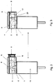
- the encoder according to the invention is connected in the preassembled state to a motor 14.
- the hub 3 is fixed via a press fit on the motor shaft 15.
- an abutment here in the form of an anvil 9, which is mounted on the circuit board 6.
- a convenient variant for mounting the encoder assembly on the electric motor is to arrange on the flange-mounted base plate bayonet-shaped fasteners. Then, by simple rotation of the encoder housing a positive connection between the encoder and motor can be made.
Landscapes
- Physics & Mathematics (AREA)
- General Physics & Mathematics (AREA)
- Transmission And Conversion Of Sensor Element Output (AREA)
Applications Claiming Priority (1)
| Application Number | Priority Date | Filing Date | Title |
|---|---|---|---|
| DE102004036903.8A DE102004036903B4 (de) | 2004-07-29 | 2004-07-29 | Encoderbaugruppe und Verfahren zur Montage einer Encoderbaugruppe |
Publications (2)
| Publication Number | Publication Date |
|---|---|
| EP1621854A2 true EP1621854A2 (fr) | 2006-02-01 |
| EP1621854A3 EP1621854A3 (fr) | 2012-06-13 |
Family
ID=35432689
Family Applications (1)
| Application Number | Title | Priority Date | Filing Date |
|---|---|---|---|
| EP05015639A Withdrawn EP1621854A3 (fr) | 2004-07-29 | 2005-07-19 | Module de codeur et son procédé de montage |
Country Status (4)
| Country | Link |
|---|---|
| US (1) | US7394219B2 (fr) |
| EP (1) | EP1621854A3 (fr) |
| JP (1) | JP4272644B2 (fr) |
| DE (1) | DE102004036903B4 (fr) |
Cited By (2)
| Publication number | Priority date | Publication date | Assignee | Title |
|---|---|---|---|---|
| EP2924396A1 (fr) * | 2014-03-24 | 2015-09-30 | Dr. Johannes Heidenhain GmbH | Élément de palpage pour un dispositif de mesure d'angle inductif |
| CN114812628A (zh) * | 2022-03-10 | 2022-07-29 | 朝阳市加华电子有限公司 | 一种新型光电编码器码盘的安装方法与装置 |
Families Citing this family (18)
| Publication number | Priority date | Publication date | Assignee | Title |
|---|---|---|---|---|
| JP5164434B2 (ja) * | 2007-05-31 | 2013-03-21 | キヤノン株式会社 | エンコーダ |
| US8125731B2 (en) * | 2008-12-30 | 2012-02-28 | Honest Sensor Corp. | Encoder module with a sliding assembly |
| CH703664A1 (de) * | 2010-08-20 | 2012-02-29 | Elesta Relays Gmbh | Positionsmessvorrichtung, insbesondere Encoder, mit Sensorkopfhalter. |
| EP2606314A2 (fr) | 2010-08-19 | 2013-06-26 | ELESTA relays GmbH | Dispositif de mesure de position et procédé de détermination d'une position absolue |
| KR20130010993A (ko) * | 2011-07-20 | 2013-01-30 | 엘지이노텍 주식회사 | 자동차의 차고센서 모듈 |
| JP2014055911A (ja) * | 2012-09-14 | 2014-03-27 | Nidec Servo Corp | 無接触型ポテンショメータ |
| DE102014118041B4 (de) | 2014-12-05 | 2021-10-07 | Pwb Encoders Gmbh | Drehgeber und Verfahren zu dessen Montage an einer Baugruppe |
| CN105783950A (zh) * | 2016-04-28 | 2016-07-20 | 长春荣德光学有限公司 | 可更换光学系统与电气系统的大孔径光电主轴编码器 |
| US10527464B2 (en) | 2016-08-18 | 2020-01-07 | Ford Global Technologies, Llc | Rotatable sensor cover |
| USD797646S1 (en) * | 2016-08-18 | 2017-09-19 | Ford Motor Company | Sensor cover |
| USD838230S1 (en) | 2016-08-18 | 2019-01-15 | Ford Motor Company | Sensor cover |
| USD809995S1 (en) * | 2016-08-18 | 2018-02-13 | Ford Motor Company | Sensor cover |
| USD838231S1 (en) | 2016-08-18 | 2019-01-15 | Ford Motor Company | Sensor cover |
| JP6404970B2 (ja) * | 2017-03-10 | 2018-10-17 | ファナック株式会社 | ロータリエンコーダ |
| CN106931998A (zh) * | 2017-04-26 | 2017-07-07 | 苏州睿牛机器人技术有限公司 | 一种新型光电编码传感器 |
| DE102020002950A1 (de) | 2019-05-21 | 2020-11-26 | Sew-Eurodrive Gmbh & Co Kg | Antrieb, aufweisend einen Elektromotor mit Rotorwelle, Winkelsensor und Haubenteil sowie Anschlussmodul, und Verfahren zum Herstellen eines Antriebs |
| USD919461S1 (en) * | 2019-06-28 | 2021-05-18 | Lyft, Inc. | Sensor component cover |
| CN114777821B (zh) * | 2022-03-10 | 2023-07-18 | 朝阳市加华电子有限公司 | 一种新型光电编码器码盘的固定方法与装置 |
Citations (2)
| Publication number | Priority date | Publication date | Assignee | Title |
|---|---|---|---|---|
| DE29520932U1 (de) | 1995-03-17 | 1996-07-18 | Ruhr Oel GmbH, 45896 Gelsenkirchen | Apparatur zur Behandlung einer wässerigen Lauge |
| EP1055915A1 (fr) | 1999-05-25 | 2000-11-29 | Pwb-Ruhlatec Industrieprodukte GmbH | Codeur avec un boítier assemblable |
Family Cites Families (19)
| Publication number | Priority date | Publication date | Assignee | Title |
|---|---|---|---|---|
| US4285595A (en) * | 1978-01-12 | 1981-08-25 | Electro-Craft Corporation | Modular encoder |
| US4184071A (en) | 1978-01-12 | 1980-01-15 | Electro-Craft Corporation | Modular encoder |
| JPS5963950A (ja) | 1983-03-18 | 1984-04-11 | Hitachi Ltd | モ−タ−の吊り下げ取付構造 |
| US5038088A (en) * | 1985-12-30 | 1991-08-06 | Arends Gregory E | Stepper motor system |
| US4794250A (en) | 1987-02-27 | 1988-12-27 | Hewlett-Packard Company | Self-gapping optical encoder |
| DE3908932A1 (de) | 1988-05-25 | 1989-12-07 | Heidenhain Gmbh Dr Johannes | Winkelmessvorrichtung |
| JPH01299415A (ja) | 1988-05-28 | 1989-12-04 | Alps Electric Co Ltd | 磁気式エンコーダ |
| US5184038A (en) | 1990-01-23 | 1993-02-02 | Kawasaki Jukogyo Kabushiki Kaisha | Method of coupling magnetic position detecting device with brushless dc motor and the coupling structure thereof |
| US5155401A (en) | 1990-06-07 | 1992-10-13 | Canon Kabushiki Kaisha | Recorder motor with attached encoder and cover |
| US5057684A (en) | 1990-08-30 | 1991-10-15 | Robbins & Myers/Electro-Craft, A Wholly Owned Sub. Of Robbins & Myers, Inc. | Unitary aligning and gapping apparatus for modular optical shaft encoder |
| EP0557564B1 (fr) | 1992-02-28 | 1995-04-12 | Dr. Johannes Heidenhain GmbH | Dispositif de montage pour un dispositif pour mesurer des angles |
| US5708496A (en) | 1996-03-11 | 1998-01-13 | Renco Encoders, Inc. | Modular optical shaft encoder having a slide gap centering mechanism and method of use |
| US5883384A (en) | 1996-04-16 | 1999-03-16 | Canon Kabushiki Kaisha | Rotational displacement information detection apparatus |
| DE19641929C2 (de) * | 1996-10-11 | 2000-01-05 | Ruhlatec Industrieprodukte | Encoder |
| EP0996213B1 (fr) | 1998-10-14 | 2001-07-04 | Siemens Aktiengesellschaft | Connecteur pour moteur, notamment pour moteur à collecteur à vitesse réglable |
| US6534888B1 (en) | 1999-03-19 | 2003-03-18 | Mannesmann Vdo Ag | Electric motor intended to be fixed to a printed circuit board |
| DE10164078A1 (de) | 2001-12-24 | 2003-07-03 | Pwb Ruhlatec Ind Prod Gmbh | Motor-Sensor-System |
| DE20120932U1 (de) | 2001-12-24 | 2002-04-04 | PWB-Ruhlatec Industrieprodukte GmbH, 53757 Sankt Augustin | Motor-Sensor-System |
| JP4496154B2 (ja) * | 2005-10-31 | 2010-07-07 | 株式会社リコー | ロータリーエンコーダ、ローラ部材、ベルト搬送装置、画像形成装置 |
-
2004
- 2004-07-29 DE DE102004036903.8A patent/DE102004036903B4/de not_active Expired - Fee Related
-
2005
- 2005-07-19 EP EP05015639A patent/EP1621854A3/fr not_active Withdrawn
- 2005-07-28 JP JP2005218249A patent/JP4272644B2/ja not_active Expired - Fee Related
- 2005-07-29 US US11/193,039 patent/US7394219B2/en not_active Expired - Fee Related
Patent Citations (2)
| Publication number | Priority date | Publication date | Assignee | Title |
|---|---|---|---|---|
| DE29520932U1 (de) | 1995-03-17 | 1996-07-18 | Ruhr Oel GmbH, 45896 Gelsenkirchen | Apparatur zur Behandlung einer wässerigen Lauge |
| EP1055915A1 (fr) | 1999-05-25 | 2000-11-29 | Pwb-Ruhlatec Industrieprodukte GmbH | Codeur avec un boítier assemblable |
Cited By (4)
| Publication number | Priority date | Publication date | Assignee | Title |
|---|---|---|---|---|
| EP2924396A1 (fr) * | 2014-03-24 | 2015-09-30 | Dr. Johannes Heidenhain GmbH | Élément de palpage pour un dispositif de mesure d'angle inductif |
| US9835476B2 (en) | 2014-03-24 | 2017-12-05 | Dr. Johannes Heidenhain Gmbh | Scanning element for an inductive angle-measuring device |
| CN114812628A (zh) * | 2022-03-10 | 2022-07-29 | 朝阳市加华电子有限公司 | 一种新型光电编码器码盘的安装方法与装置 |
| CN114812628B (zh) * | 2022-03-10 | 2023-09-19 | 朝阳市加华电子有限公司 | 一种光电编码器码盘的安装方法 |
Also Published As
| Publication number | Publication date |
|---|---|
| JP4272644B2 (ja) | 2009-06-03 |
| US20060022531A1 (en) | 2006-02-02 |
| DE102004036903B4 (de) | 2019-07-04 |
| JP2006038867A (ja) | 2006-02-09 |
| EP1621854A3 (fr) | 2012-06-13 |
| US7394219B2 (en) | 2008-07-01 |
| DE102004036903A1 (de) | 2006-03-23 |
Similar Documents
| Publication | Publication Date | Title |
|---|---|---|
| EP1621854A2 (fr) | Module de codeur et son procédé de montage | |
| EP0836079B1 (fr) | Codeur rotatif | |
| DE102004038623B4 (de) | Baueinheit zum Verbinden eines elektrischen Teils mit einer Leiterplatte, Bremsöldruck-Regel- bzw. Steuereinheit sowie korrespondierendes Verfahren | |
| DE69004165T2 (de) | Kreuzgelenkmodul. | |
| DE29721908U1 (de) | Anordnung betreffend eine elektrische und/oder elektronische Bauelemente tragende Elektrikplatte mit einem elektrischen Steckverbinder und einer Abdeckung | |
| EP1895277B1 (fr) | Codeur rotatif avec aide de montage | |
| DE69015097T2 (de) | Kraftfahrzeugskarosseriekomponente, umfassend eine Beleuchtungsvorrichtung. | |
| EP1468758B1 (fr) | Matrice pour jeu d'outils pour réaliser des joints mécaniques | |
| EP0368010A1 (fr) | Segment d'encollage pouvant être emmanché et serré sur un arbre d'entraînement | |
| EP1677012A1 (fr) | Pièce en plastique | |
| DE2747272A1 (de) | Halterung fuer elektronische bauelemente | |
| DE112019004011T5 (de) | Montagesystem für ein Kastenprofil | |
| DE10219245A1 (de) | Verfahren und Vorrichtung zum Trennen einer Geberwelle eines Drehgebers von einer Antriebswelle | |
| WO1998058764A1 (fr) | Dispositif de preparation et/ou de montage | |
| EP1144874A2 (fr) | Systeme pour assembler deux parties | |
| EP3951317B1 (fr) | Dispositif d'application d'un marquage de mesure à un boulon de mesure | |
| DE4343112B4 (de) | Membranfederkupplung mit durch Zungen abgestützter Membranfeder | |
| DE102009033695B4 (de) | Personenkraftwagen und Montageverfahren | |
| EP3837740B1 (fr) | Connecteur électrique | |
| WO2009053172A1 (fr) | Unité porteuse pour le montage d'une transmission à moyen de traction, et procédé de montage | |
| DE102006022890A1 (de) | Befestigungssystem mit einem Clip | |
| DE20318994U1 (de) | Torantriebsgehäuse | |
| DE3506125C2 (fr) | ||
| DE102024200973A1 (de) | Sensoranordnung | |
| EP1800048B1 (fr) | Dispositif permettant de relier des extremites de tuyaux |
Legal Events
| Date | Code | Title | Description |
|---|---|---|---|
| PUAI | Public reference made under article 153(3) epc to a published international application that has entered the european phase |
Free format text: ORIGINAL CODE: 0009012 |
|
| AK | Designated contracting states |
Kind code of ref document: A2 Designated state(s): AT BE BG CH CY CZ DE DK EE ES FI FR GB GR HU IE IS IT LI LT LU LV MC NL PL PT RO SE SI SK TR |
|
| AX | Request for extension of the european patent |
Extension state: AL BA HR MK YU |
|
| REG | Reference to a national code |
Ref country code: HK Ref legal event code: DE Ref document number: 1092211 Country of ref document: HK |
|
| 19U | Interruption of proceedings before grant |
Effective date: 20090701 |
|
| 19W | Proceedings resumed before grant after interruption of proceedings |
Effective date: 20100802 |
|
| RAP1 | Party data changed (applicant data changed or rights of an application transferred) |
Owner name: PWB ENCODERS GMBH |
|
| PUAL | Search report despatched |
Free format text: ORIGINAL CODE: 0009013 |
|
| AK | Designated contracting states |
Kind code of ref document: A3 Designated state(s): AT BE BG CH CY CZ DE DK EE ES FI FR GB GR HU IE IS IT LI LT LU LV MC NL PL PT RO SE SI SK TR |
|
| AX | Request for extension of the european patent |
Extension state: AL BA HR MK YU |
|
| RIC1 | Information provided on ipc code assigned before grant |
Ipc: G01D 5/347 20060101ALI20120509BHEP Ipc: G01D 11/24 20060101AFI20120509BHEP |
|
| REG | Reference to a national code |
Ref country code: HK Ref legal event code: WD Ref document number: 1092211 Country of ref document: HK |
|
| AKY | No designation fees paid | ||
| REG | Reference to a national code |
Ref country code: DE Ref legal event code: R108 |
|
| REG | Reference to a national code |
Ref country code: DE Ref legal event code: R108 Effective date: 20130220 |
|
| STAA | Information on the status of an ep patent application or granted ep patent |
Free format text: STATUS: THE APPLICATION IS DEEMED TO BE WITHDRAWN |
|
| 18D | Application deemed to be withdrawn |
Effective date: 20121214 |