EP3837740B1 - Connecteur électrique - Google Patents
Connecteur électrique Download PDFInfo
- Publication number
- EP3837740B1 EP3837740B1 EP19755604.6A EP19755604A EP3837740B1 EP 3837740 B1 EP3837740 B1 EP 3837740B1 EP 19755604 A EP19755604 A EP 19755604A EP 3837740 B1 EP3837740 B1 EP 3837740B1
- Authority
- EP
- European Patent Office
- Prior art keywords
- plug
- template
- opening
- connector
- contact
- Prior art date
- Legal status (The legal status is an assumption and is not a legal conclusion. Google has not performed a legal analysis and makes no representation as to the accuracy of the status listed.)
- Active
Links
Images

Classifications
-
- H—ELECTRICITY
- H01—ELECTRIC ELEMENTS
- H01R—ELECTRICALLY-CONDUCTIVE CONNECTIONS; STRUCTURAL ASSOCIATIONS OF A PLURALITY OF MUTUALLY-INSULATED ELECTRICAL CONNECTING ELEMENTS; COUPLING DEVICES; CURRENT COLLECTORS
- H01R13/00—Details of coupling devices of the kinds covered by groups H01R12/70 or H01R24/00 - H01R33/00
- H01R13/46—Bases; Cases
- H01R13/52—Dustproof, splashproof, drip-proof, waterproof, or flameproof cases
- H01R13/5205—Sealing means between cable and housing, e.g. grommet
- H01R13/5208—Sealing means between cable and housing, e.g. grommet having at least two cable receiving openings
-
- H—ELECTRICITY
- H01—ELECTRIC ELEMENTS
- H01R—ELECTRICALLY-CONDUCTIVE CONNECTIONS; STRUCTURAL ASSOCIATIONS OF A PLURALITY OF MUTUALLY-INSULATED ELECTRICAL CONNECTING ELEMENTS; COUPLING DEVICES; CURRENT COLLECTORS
- H01R43/00—Apparatus or processes specially adapted for manufacturing, assembling, maintaining, or repairing of line connectors or current collectors or for joining electric conductors
- H01R43/005—Apparatus or processes specially adapted for manufacturing, assembling, maintaining, or repairing of line connectors or current collectors or for joining electric conductors for making dustproof, splashproof, drip-proof, waterproof, or flameproof connection, coupling, or casing
Definitions
- the invention relates to a connector for providing an electrical connection to a device part in a motor vehicle, such as a door handle, an engine or an airbag control unit, according to the preamble of the independent device claim.
- the invention also relates to a method for producing a corresponding connector according to the preamble of the independent method claim.
- the plug contacts are usually simply overmolded with a potting compound within a connector housing.
- overmolding can only take place after the final assembly of all contact elements in the connector housing.
- this limits the freedom of assembly with different plug contacts or with a different number of plug contacts and excludes subsequent conversion and/or subsequent maintenance of such connectors.
- the punched edges of the plug contacts for passing through the collective seals must be carefully manufactured without burrs in order to avoid damage to the seal during contact assembly, which involves considerable manufacturing effort.
- Examples of connectors are available from the documents EP 1 556 924 B1 , WO 2015/121874 A1 , JP 2003 092 165 A , DE 196 41 408 A1 and EP 1 001 496 A2 known.
- the object of the invention is therefore to at least partially overcome at least one disadvantage known from the prior art in a connector.
- a connector for providing an electrical connection to a device part in a motor vehicle such as a door handle, an engine or an airbag control unit, which is simple, inexpensive and quick to manufacture, which allows automatic assembly of the connector, which is reliably sealed, which has an extended service life and which can be assembled and/or converted in an adaptable manner and which can be easily maintained.
- the object according to the invention is achieved by a connector for providing an electrical connection with the features of the independent device claim and by a method for producing a corresponding connector with the features of the independent method claim.
- Preferred developments of the invention are listed in the dependent claims.
- the invention provides a connector for providing an electrical connection, in particular to a device part in a motor vehicle, such as a door handle, an engine or an airbag control unit, comprising: a collective seal or a mat seal with at least one through-opening and at least one electrically conductive plug contact which can be passed through the at least one through-opening of the collective seal.
- a connector for providing an electrical connection in particular to a device part in a motor vehicle, such as a door handle, an engine or an airbag control unit, comprising: a collective seal or a mat seal with at least one through-opening and at least one electrically conductive plug contact which can be passed through the at least one through-opening of the collective seal.
- a template is provided for the through-opening in order to support the plug contact when passing through the through-opening of the collective seal.
- the template in the sense of the invention can be understood as a guide and/or centering device, in particular a guide and/or centering film, with a corresponding guide unit for the through-opening.
- the template in particular the guide unit, can in turn have a mapping guide geometry for the through-opening.
- the guide geometry can preferably be designed as a (3D) guide geometry with a certain depth.
- the template can advantageously be designed like a film and arranged flat on one side of the collective seal. By placing the template on one side of the collective seal, the guide geometry can at least partially penetrate into the through-opening.
- the connector according to the invention is particularly suitable as a device connector, preferably on the male side or on the device side of two complementary plug connections, which can have relatively hard and/or thick plug contacts.
- the invention can also be advantageous for connectors on the female side in order to increase the quality and safety of the plug sockets and to simplify their manufacture.
- the plug contact in a plug contact in the sense of the invention, can be designed with a connecting cable on both the female side and the male side.
- a template for the through-opening is provided for the manufacture of the plug connector, which aligns the tip of the contact plug with the through-opening of the collective seal when the plug contact is passed through, so that the plug tip does not penetrate the seal, but is guided specifically through the through-opening in the collective seal.
- the template aligns the plug contact along the surface of the template, preferably on a guide unit of the template, until the plug tip precisely hits the through-opening in the mat seal and is then gently guided through this through-opening.
- This can be achieved by a special shape of a guide geometry, e.g. funnel-shaped, which can at least partially protrude into the through-opening of the collective seal, and/or a specific material composition, e.g.
- the shape of the guide geometry can influence the angle of incidence of the connector tip on the surface of the collective seal, which can cause it to slide along the template instead of the connector tip piercing the material of the mat seal.
- the template can preferably be designed in the form of an elastic film, which can cause the connector tip to touch down in a cushioned manner.
- the template can be applied as a retrofit component for the connector, at least temporarily or permanently.
- the template according to the invention can be formed with a corresponding guide geometry for all through-openings of the collective seal.
- the template according to the invention can have a guide geometry that depicts all through-openings of the collective seal.
- the template can have a guide unit for each through-opening.
- the respective guide unit can have a funnel-shaped guide geometry that tapers in the direction of the through-openings of the collective seal.
- the guide unit can also have a complementary opening for the through-opening at a lower point. It is also conceivable that the guide unit can have flaps that can be opened in the direction of the through holes of the collective seal.
- the guide unit can have a predetermined breaking geometry, e.g. between the flaps, to facilitate the passage of the plug tip.
- the invention can provide for a plug connector that the template is designed to be elastic and/or film-like.
- a template can advantageously absorb shock and deform flexibly in order to be able to align the plug contact in an advantageous manner.
- such a template can have a thin material thickness and can be arranged in the plug connector without significant loss of installation space.
- the invention can provide that the template rests loosely on the collective seal. This means that the template can be installed within the connector or the connector can be assembled easily and without great assembly effort.
- the template can have a material thickness of 0.1 mm to 0.2 mm, preferably 0.15 mm. In this way, a thin template with elastic properties can be provided.
- the template can have a depth of 1 mm to 1.2 mm, in particular 1.1 mm. This allows a guide unit of the template to partially penetrate into the respective through-opening so that the plug tip can be precisely aligned with the through-opening of the collective seal.
- the invention can provide for a plug connector that the template has at least one guide unit to align the plug contact in the direction of the through-opening, wherein the guide unit in particular can have a funnel-shaped guide geometry.
- the funnel-shaped guide geometry can have a depth of 0.5 mm to 0.7 mm, preferably 0.6 mm.
- the template can provide an imaging guide geometry for the through-opening.
- the guide unit advantageously ensures that the plug tip first hits the template when the collective seal is fitted and is guided by the guide unit onto the through hole before it is passed through the through hole.
- the template according to the invention has hinged guide elements that can be opened in the through-opening of the collective seal through the plug contact. This makes it considerably easier to align the plug tip and enables the plug tip to be guided through the through-opening almost seamlessly.
- the guide elements can preferably be attached to the respective guide unit using hinge elements.
- the invention provides for the connector that the template has a predetermined breaking geometry between the hinged guide elements, which can be opened by the plug contact in the direction of the through-opening.
- the template can have a complementary opening for the through-opening.
- the predetermined breaking geometry advantageously ensures that after the connector tip has been aligned, the connector tip can be passed through the through-opening without any problems.
- the template can have a collar element, which can be used to position a holding element or a seal holding grid for the template on a plug housing.
- the collar element can surround the template in a bowl-like manner, so that a receptacle for the holding element is created within the template.
- the template can also be arranged on the collective seal in a captive manner. The template is thus arranged between the collective seal and the holding element.
- the collar element can surround the foot of the holding element in the area of the support surface on the template.
- the object according to the invention is achieved by a method for producing a connector, comprising: a collective seal with at least one through-opening and at least one electrically conductive plug contact, which is passed through the at least one through-opening of the collective seal.
- a method for producing a connector comprising: a collective seal with at least one through-opening and at least one electrically conductive plug contact, which is passed through the at least one through-opening of the collective seal.
- the invention provides that when passing the plug contact through the through-opening of the collective seal, a template is used in order to guide the plug contact through the through-opening of the collective seal in a targeted manner.
- the method according to the invention achieves the same advantages that were described above in connection with the connector according to the invention. To avoid repetition, reference is made to this in full here.
- the method can provide that the template remains on the collective seal after the plug contact has been passed through the through-opening of the collective seal during normal operation of the connector. This can speed up the commissioning of the connector.
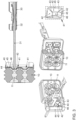
- the Figure 1 shows a connector 100 after fitting a collective seal 10 in the form of a mat seal 10 with an electrically conductive plug contact 30.
- the mat seal 10 has several through openings 11 for a plug contact 30 each, which can be fitted or left free as required.
- the mat seal 10 is housed together with a holding element 20 or a seal holding grid with an opening 21 for a connecting line 33 in a connector housing 50.
- the collective seals 10 are usually only fitted with relatively thin plug contacts 30 in the connectors 100 on the socket side (female). Thicker plug contacts 30 are used in the connectors 100 on the male side than on the socket side. When such thicker contact elements are passed through the mat seal 10, it may happen that the plug contacts 30 can damage the relatively soft mat seal 10, for example by piercing it.
- the invention provides a connector 100 which makes it possible to gently equip the collective seal 10 even in the case of a connector 100 on the plug side with relatively thick plug contacts 30 without damaging the collective seal 10.
- the invention provides a template 40 for the through-opening 11 in order to support the plug contact 30 when passing through the through-opening 11 of the collective seal 10.
- the template 40 can be designed in the form of a guide and/or centering foil.
- the guide foil is designed with a corresponding guide unit 41 for the respective through-opening 11 of the mat seal 10.
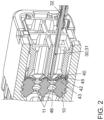
- the template 40 in particular the guide unit 41, can have a mapping guide geometry for the through-opening 11 (cf. the Figure 2 ).
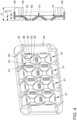
- the guide geometry can be designed as a (3D) guide geometry with a specific depth t2 (cf. the Figure 4 ).
- the template 40 can be applied as a retrofit component for the connector 100, at least temporarily for equipping the mat seal 10 or permanently for the operation of the connector 100.
- the template 40 is arranged flat on one side of the collective seal 10 so that the respective guide unit 41 can at least partially penetrate into the corresponding through-opening 11 of the mat seal 10 (see the Figure 2 ).
- the template 40 only needs to be arranged loosely on the collective seal 10.
- the template 40 can no longer slip.
- the template 40 is positioned between the mat seal 10 and the holding element 20.
- the template 40 can also have a collar element 44 in order to at least partially enclose the holding element 20 in the area of the support surface on the template 40. The template 40 is thus reliably held in its position.
- a cover grille 51 or a locking plate is then placed in front of the other side of the connector 100.
- the cover grille 51 and/or the connector housing 50 in the area of the cover grille 51 can interact with a connector geometry 32 or with a so-called contact box on the plug contact 30 in a form-fitting and/or force-fitting manner in order to fasten the plug contact 30 to the connector 100.
- the template 40 helps in guiding the plug tip 31 through the through opening 11 of the collective seal 10 by precisely aligning the plug tip 31 with the aid of the guide unit 41 so that the plug tip 31 does not penetrate into the collective seal 10, but is guided specifically through the through opening 11 in the collective seal 10.
- the template 40 causes the plug contact 30 to be aligned with the guide unit 41 of the template 40 until the plug tip 31 exactly hits the through-opening 11 in the mat seal 10. The plug tip 31 can then be gently guided through the through-opening 11.
- the template 40 in the sense of the invention can also be formed for all through holes 11 of the collective seal 10 with a corresponding guide geometry, which can depict all through holes 11 of the collective seal 10 (cf. the Figure 4 ).
- the template 40 can have a guide unit 41 for each through-opening 11.
- the respective guide unit 41 can have a funnel-shaped guide geometry that can taper in the direction of the through-openings 11 of the collective seal 10.
- the guide unit 41 can have guide elements 42 in the form of flaps that can be opened in the direction of the through opening 11 of the collective seal 10.
- the guide elements 42 can preferably be attached to the respective guide unit 41 using hinge elements 45, in particular in the form of film hinges.
- the guide unit 41 can have a predetermined breaking geometry 43, for example between the flaps, in order to facilitate the passage of the plug tip 31.
- the guide unit 41 can have a complementary opening 46 for the through opening 11 at a lower point.
- the template 40 is unique within the scope of the invention.
- the template 40 can have a material thickness d of 0.1 mm to 0.2 mm, preferably 0.15 mm and a depth t1 of 1 mm to 1.2 mm, in particular 1.1 mm.
- the depth t2 of the funnel-shaped guide geometry can be in the range of 0.5 mm to 0.7 mm, preferably 0.6 mm.
Landscapes
- Engineering & Computer Science (AREA)
- Manufacturing & Machinery (AREA)
- Connector Housings Or Holding Contact Members (AREA)
Claims (9)
- Connecteur électrique (100) destiné à fournir une connexion électrique, présentant :un joint collecteur (10) comportant au moins une ouverture de passage (11) et au moins un contact à fiche (30) électriquement conducteur,lequel peut être guidé à travers l'au moins une ouverture de passage (11) du joint collecteur (10),dans lequel un gabarit (40) est prévu pour l'ouverture de passage (11) pour soutenir le contact à fiche (30) lors du passage à travers l'ouverture de passage (11) du joint collecteur (10),dans lequel le gabarit (40) présente des éléments de guidage (42) rabattables qui peuvent être ouverts dans l'ouverture de passage (11) du joint collecteur (10) par le contact enfichable (30),caractérisé en ce que le gabarit (40) présente, entre les éléments de guidage (42) rabattables, une géométrie de rupture (43) qui peut être ouverte par le contact à fiche (30) en direction de l'ouverture de passage (11).
- Connecteur électrique (100) selon la revendication 1,
caractérisé en ce que le gabarit (40) est réalisé de manière élastique et/ou en forme de feuille. - Connecteur électrique (100) selon la revendication 1,
caractérisé en ce que le gabarit (40) s'applique de manière lâche contre le joint collecteur (10). - Connecteur électrique (100) selon l'une des revendications précédentes,caractérisé en ce que le gabarit (40) présente une épaisseur de matériau (d) de 0,1 mm à 0,2 mm, de préférence de 0,15 mm,et/ou en ce que le gabarit (40) présente une profondeur (t1) de 1 mm à 1,2 mm, en particulier de 1,1 mm.
- Connecteur électrique (100) selon l'une des revendications précédentes,caractérisé en ce que le gabarit (40) présente au moins une unité de guidage (41) pour orienter le contact à fiche (30) en direction de l'ouverture de passage (11),et/ou en ce que l'unité de guidage (41) présente une géométrie de guidage en forme d'entonnoir,et/ou en ce que la géométrie de guidage en forme d'entonnoir présente une profondeur (t2) de 0,5 mm à 0,7 mm, de préférence de 0,6 mm.
- Connecteur électrique (100) selon la revendication précédente,
caractérisé en ce que les éléments de guidage (42) sont fixés à l'unité de guidage (41) respective à l'aide d'éléments de charnière (45). - Connecteur électrique (100) selon l'une des revendications précédentes,
caractérisé en ce que le gabarit (40) présente un élément de collerette (44) qui sert au positionnement d'un élément de maintien (20) pour le gabarit (40) sur un boîtier de connecteur (50). - Procédé destiné à fabriquer un connecteur électrique (100), présentant:un joint collecteur (10) comportant au moins une ouverture de passage (11) et au moins un contact à fiche (30) électriquement conducteur,lequel est guidé à travers l'au moins une ouverture de passage (11) du joint collecteur (10),dans lequel, lors du passage du contact à fiche (30) à travers l'ouverture de passage (11) du joint collecteur (10), un gabarit (40) est utilisé pour guider de manière ciblée le contact à fiche (30) à travers l'ouverture de passage (11) du joint collecteur (10), dans lequel le gabarit (40) présente des éléments de guidage (42) rabattables qui sont ouverts dans l'ouverture de passage (11) du joint collecteur (10) par le contact enfichable (30),caractérisé en ce que le gabarit (40) présente, entre les éléments de guidage (42) rabattables, une géométrie de rupture (43) qui est ouverte par le contact à fiche (30) en direction de l'ouverture de passage (11).
- Procédé selon la revendication précédente,
caractérisé en ce que le gabarit (40) reste sur le joint collecteur (10) après le passage du contact à fiche (30) à travers l'ouverture de passage (11) du joint collecteur (10) pendant le fonctionnement normal du connecteur électrique (100).
Applications Claiming Priority (2)
| Application Number | Priority Date | Filing Date | Title |
|---|---|---|---|
| DE102018120104.4A DE102018120104B4 (de) | 2018-08-17 | 2018-08-17 | Steckverbinder zum Bereitstellen eines elektrischen Anschlusses und Verfahren |
| PCT/EP2019/071941 WO2020035566A1 (fr) | 2018-08-17 | 2019-08-15 | Connecteur électrique |
Publications (2)
| Publication Number | Publication Date |
|---|---|
| EP3837740A1 EP3837740A1 (fr) | 2021-06-23 |
| EP3837740B1 true EP3837740B1 (fr) | 2024-10-09 |
Family
ID=67660562
Family Applications (1)
| Application Number | Title | Priority Date | Filing Date |
|---|---|---|---|
| EP19755604.6A Active EP3837740B1 (fr) | 2018-08-17 | 2019-08-15 | Connecteur électrique |
Country Status (5)
| Country | Link |
|---|---|
| US (1) | US11539159B2 (fr) |
| EP (1) | EP3837740B1 (fr) |
| CN (1) | CN113169477B (fr) |
| DE (1) | DE102018120104B4 (fr) |
| WO (1) | WO2020035566A1 (fr) |
Families Citing this family (1)
| Publication number | Priority date | Publication date | Assignee | Title |
|---|---|---|---|---|
| DE102020133319A1 (de) * | 2020-12-14 | 2022-06-15 | Lear Corporation | Elektrische Steckverbinder mit verjüngten Anschlussdurchgängen |
Citations (1)
| Publication number | Priority date | Publication date | Assignee | Title |
|---|---|---|---|---|
| EP1001496A2 (fr) * | 1998-11-13 | 2000-05-17 | Framatome Connectors International | Connecteur électrique |
Family Cites Families (20)
| Publication number | Priority date | Publication date | Assignee | Title |
|---|---|---|---|---|
| JP2921641B2 (ja) * | 1994-05-23 | 1999-07-19 | 矢崎総業株式会社 | 防水コネクタ |
| JPH09106851A (ja) | 1995-10-09 | 1997-04-22 | Yazaki Corp | 防水コネクタ |
| JPH09289057A (ja) * | 1996-04-19 | 1997-11-04 | Yazaki Corp | 防水コネクタ |
| JP3547988B2 (ja) * | 1998-03-31 | 2004-07-28 | 矢崎総業株式会社 | 防水コネクタ及び防水処理方法 |
| JP3380528B2 (ja) * | 2000-07-13 | 2003-02-24 | 日本圧着端子製造株式会社 | 防水コネクタ |
| JP2002122524A (ja) | 2000-10-13 | 2002-04-26 | Sumitomo Metal Mining Co Ltd | 透過電子顕微鏡用試料の作製方法 |
| JP2002164143A (ja) * | 2000-11-27 | 2002-06-07 | Sumitomo Wiring Syst Ltd | 防水コネクタにおける端子金具の挿抜方法及びこれに使用する治具 |
| JP2003092165A (ja) * | 2001-09-18 | 2003-03-28 | Sumitomo Wiring Syst Ltd | 防水コネクタ |
| DE10300264A1 (de) * | 2003-01-08 | 2004-08-19 | Delphi Technologies, Inc., Troy | Blockdichtungssystem |
| DE502004003207D1 (de) * | 2004-01-16 | 2007-04-26 | Delphi Tech Inc | Elektrischer Verbinder |
| JP5203094B2 (ja) * | 2008-04-03 | 2013-06-05 | 矢崎総業株式会社 | コネクタ用パッキン構造 |
| DE102011006836A1 (de) * | 2011-04-06 | 2012-10-11 | Robert Bosch Gmbh | Steckverbinder mit Einführhilfe zum Einführen von Kontaktelementen |
| US8969741B2 (en) * | 2011-06-10 | 2015-03-03 | Cooper Technologies Company | Damming device for cable sealing |
| DE102011080347A1 (de) * | 2011-08-03 | 2013-02-07 | Robert Bosch Gmbh | Geschlossene Dichtmatte |
| JP2013073719A (ja) * | 2011-09-27 | 2013-04-22 | Sumitomo Wiring Syst Ltd | コネクタ |
| JP2014017171A (ja) * | 2012-07-10 | 2014-01-30 | Sumitomo Wiring Syst Ltd | 防水コネクタ |
| DE102012223431A1 (de) * | 2012-12-17 | 2014-06-18 | Robert Bosch Gmbh | Gehäuse für eine elektrische Maschine mit einer Dichtung |
| WO2015121874A1 (fr) * | 2014-02-11 | 2015-08-20 | Tyco Electronics Amp Gmbh | Couvercle pour boîtier de connecteur et boîtier de connecteur ayant un tel couvercle |
| JP6370210B2 (ja) * | 2014-12-24 | 2018-08-08 | 住友電装株式会社 | 防水コネクタ |
| US9960523B2 (en) * | 2015-04-22 | 2018-05-01 | Yazaki Corporation | Mat seal cover of waterproof connector |
-
2018
- 2018-08-17 DE DE102018120104.4A patent/DE102018120104B4/de active Active
-
2019
- 2019-08-15 CN CN201980068482.5A patent/CN113169477B/zh active Active
- 2019-08-15 US US17/268,610 patent/US11539159B2/en active Active
- 2019-08-15 EP EP19755604.6A patent/EP3837740B1/fr active Active
- 2019-08-15 WO PCT/EP2019/071941 patent/WO2020035566A1/fr not_active Ceased
Patent Citations (1)
| Publication number | Priority date | Publication date | Assignee | Title |
|---|---|---|---|---|
| EP1001496A2 (fr) * | 1998-11-13 | 2000-05-17 | Framatome Connectors International | Connecteur électrique |
Also Published As
| Publication number | Publication date |
|---|---|
| WO2020035566A1 (fr) | 2020-02-20 |
| EP3837740A1 (fr) | 2021-06-23 |
| DE102018120104B4 (de) | 2025-06-12 |
| US11539159B2 (en) | 2022-12-27 |
| US20210242621A1 (en) | 2021-08-05 |
| DE102018120104A1 (de) | 2020-02-20 |
| CN113169477A (zh) | 2021-07-23 |
| CN113169477B (zh) | 2023-09-05 |
Similar Documents
| Publication | Publication Date | Title |
|---|---|---|
| EP3235060B1 (fr) | Connecteur enfichable | |
| DE102009025113A1 (de) | Einpresskontakt zur Verbindung eines elektronischen Bauelementes mit einer Leiterplatte sowie Einpresswerkzeug | |
| EP3224907B1 (fr) | Connecteur pour films de circuit imprimé flexibles | |
| DE202014106058U1 (de) | Steckverbinder | |
| DE112010004634T5 (de) | Draht-Halter | |
| EP1869743A1 (fr) | Dispositif et procede pour le passage universel de cables | |
| WO2016096253A1 (fr) | Dispositif de détection, en particulier pour l'utilisation dans un véhicule automobile | |
| DE102013211455A1 (de) | Sekundärverriegelung für einen Stecker | |
| DE102007009644A1 (de) | Elektronische Baugruppe mit Steckverbindung | |
| DE102017108320A1 (de) | Flachteilhalter für die Befestigung eines Flachteils an einem Rahmengestell eines Schaltschranks und ein entsprechender Schaltschrank | |
| EP4029132B1 (fr) | Dispositif d'entraînement électrique et ensemble d'entraînement | |
| EP3837740B1 (fr) | Connecteur électrique | |
| EP3729564B1 (fr) | Connecteur enfichable | |
| EP2169776A1 (fr) | Fiche de raccordement électrique | |
| DE102013209435A1 (de) | Steckerverbindung mit einem zur Vermeidung von Spänen optimierten Führungselement | |
| DE102006022382A1 (de) | Vorrichtung und Verfahren zur Befestigung eines Wischermotors an ein Wischergestänge | |
| EP2337161A1 (fr) | Agencement de prise et dispositif d'étanchéification pour au moins une ligne, notamment une ligne électrique | |
| DE102020111030A1 (de) | Kontaktanordnung | |
| DE102015121832B4 (de) | Steckverbinder zur elektrischen Direktkontaktierung und Steckverbindung | |
| EP3946994B1 (fr) | Procédé pour l'établissement d'une connexion compensée en tolérance entre un premier composant et un deuxième composant et entraînement électrique | |
| DE102009041393A1 (de) | Befestigungsanordnung | |
| EP2018693B1 (fr) | Profile electrique pour traversees de cables | |
| EP1986281B1 (fr) | Procédé de fabrication d'une liaison électrique conductrice | |
| DE102012108859B4 (de) | Elektronikmodul | |
| DE102020131254A1 (de) | Plattenaufbauten zur durchführung elektrischer leiter |
Legal Events
| Date | Code | Title | Description |
|---|---|---|---|
| STAA | Information on the status of an ep patent application or granted ep patent |
Free format text: STATUS: UNKNOWN |
|
| STAA | Information on the status of an ep patent application or granted ep patent |
Free format text: STATUS: THE INTERNATIONAL PUBLICATION HAS BEEN MADE |
|
| PUAI | Public reference made under article 153(3) epc to a published international application that has entered the european phase |
Free format text: ORIGINAL CODE: 0009012 |
|
| STAA | Information on the status of an ep patent application or granted ep patent |
Free format text: STATUS: REQUEST FOR EXAMINATION WAS MADE |
|
| 17P | Request for examination filed |
Effective date: 20210309 |
|
| AK | Designated contracting states |
Kind code of ref document: A1 Designated state(s): AL AT BE BG CH CY CZ DE DK EE ES FI FR GB GR HR HU IE IS IT LI LT LU LV MC MK MT NL NO PL PT RO RS SE SI SK SM TR |
|
| DAV | Request for validation of the european patent (deleted) | ||
| DAX | Request for extension of the european patent (deleted) | ||
| STAA | Information on the status of an ep patent application or granted ep patent |
Free format text: STATUS: EXAMINATION IS IN PROGRESS |
|
| 17Q | First examination report despatched |
Effective date: 20220928 |
|
| GRAP | Despatch of communication of intention to grant a patent |
Free format text: ORIGINAL CODE: EPIDOSNIGR1 |
|
| STAA | Information on the status of an ep patent application or granted ep patent |
Free format text: STATUS: GRANT OF PATENT IS INTENDED |
|
| INTG | Intention to grant announced |
Effective date: 20240529 |
|
| GRAS | Grant fee paid |
Free format text: ORIGINAL CODE: EPIDOSNIGR3 |
|
| GRAA | (expected) grant |
Free format text: ORIGINAL CODE: 0009210 |
|
| STAA | Information on the status of an ep patent application or granted ep patent |
Free format text: STATUS: THE PATENT HAS BEEN GRANTED |
|
| AK | Designated contracting states |
Kind code of ref document: B1 Designated state(s): AL AT BE BG CH CY CZ DE DK EE ES FI FR GB GR HR HU IE IS IT LI LT LU LV MC MK MT NL NO PL PT RO RS SE SI SK SM TR |
|
| REG | Reference to a national code |
Ref country code: CH Ref legal event code: EP |
|
| REG | Reference to a national code |
Ref country code: DE Ref legal event code: R096 Ref document number: 502019012277 Country of ref document: DE |
|
| REG | Reference to a national code |
Ref country code: IE Ref legal event code: FG4D Free format text: LANGUAGE OF EP DOCUMENT: GERMAN |
|
| P01 | Opt-out of the competence of the unified patent court (upc) registered |
Free format text: CASE NUMBER: APP_53748/2024 Effective date: 20240927 |
|
| REG | Reference to a national code |
Ref country code: LT Ref legal event code: MG9D |
|
| REG | Reference to a national code |
Ref country code: NL Ref legal event code: MP Effective date: 20241009 |
|
| PG25 | Lapsed in a contracting state [announced via postgrant information from national office to epo] |
Ref country code: NL Free format text: LAPSE BECAUSE OF FAILURE TO SUBMIT A TRANSLATION OF THE DESCRIPTION OR TO PAY THE FEE WITHIN THE PRESCRIBED TIME-LIMIT Effective date: 20241009 |
|
| PG25 | Lapsed in a contracting state [announced via postgrant information from national office to epo] |
Ref country code: NL Free format text: LAPSE BECAUSE OF FAILURE TO SUBMIT A TRANSLATION OF THE DESCRIPTION OR TO PAY THE FEE WITHIN THE PRESCRIBED TIME-LIMIT Effective date: 20241009 |
|
| PG25 | Lapsed in a contracting state [announced via postgrant information from national office to epo] |
Ref country code: IS Free format text: LAPSE BECAUSE OF FAILURE TO SUBMIT A TRANSLATION OF THE DESCRIPTION OR TO PAY THE FEE WITHIN THE PRESCRIBED TIME-LIMIT Effective date: 20250209 Ref country code: HR Free format text: LAPSE BECAUSE OF FAILURE TO SUBMIT A TRANSLATION OF THE DESCRIPTION OR TO PAY THE FEE WITHIN THE PRESCRIBED TIME-LIMIT Effective date: 20241009 Ref country code: PT Free format text: LAPSE BECAUSE OF FAILURE TO SUBMIT A TRANSLATION OF THE DESCRIPTION OR TO PAY THE FEE WITHIN THE PRESCRIBED TIME-LIMIT Effective date: 20250210 |
|
| PG25 | Lapsed in a contracting state [announced via postgrant information from national office to epo] |
Ref country code: FI Free format text: LAPSE BECAUSE OF FAILURE TO SUBMIT A TRANSLATION OF THE DESCRIPTION OR TO PAY THE FEE WITHIN THE PRESCRIBED TIME-LIMIT Effective date: 20241009 |
|
| PG25 | Lapsed in a contracting state [announced via postgrant information from national office to epo] |
Ref country code: BG Free format text: LAPSE BECAUSE OF FAILURE TO SUBMIT A TRANSLATION OF THE DESCRIPTION OR TO PAY THE FEE WITHIN THE PRESCRIBED TIME-LIMIT Effective date: 20241009 |
|
| PG25 | Lapsed in a contracting state [announced via postgrant information from national office to epo] |
Ref country code: ES Free format text: LAPSE BECAUSE OF FAILURE TO SUBMIT A TRANSLATION OF THE DESCRIPTION OR TO PAY THE FEE WITHIN THE PRESCRIBED TIME-LIMIT Effective date: 20241009 |
|
| PG25 | Lapsed in a contracting state [announced via postgrant information from national office to epo] |
Ref country code: NO Free format text: LAPSE BECAUSE OF FAILURE TO SUBMIT A TRANSLATION OF THE DESCRIPTION OR TO PAY THE FEE WITHIN THE PRESCRIBED TIME-LIMIT Effective date: 20250109 |
|
| PG25 | Lapsed in a contracting state [announced via postgrant information from national office to epo] |
Ref country code: LV Free format text: LAPSE BECAUSE OF FAILURE TO SUBMIT A TRANSLATION OF THE DESCRIPTION OR TO PAY THE FEE WITHIN THE PRESCRIBED TIME-LIMIT Effective date: 20241009 Ref country code: GR Free format text: LAPSE BECAUSE OF FAILURE TO SUBMIT A TRANSLATION OF THE DESCRIPTION OR TO PAY THE FEE WITHIN THE PRESCRIBED TIME-LIMIT Effective date: 20250110 |
|
| PG25 | Lapsed in a contracting state [announced via postgrant information from national office to epo] |
Ref country code: PL Free format text: LAPSE BECAUSE OF FAILURE TO SUBMIT A TRANSLATION OF THE DESCRIPTION OR TO PAY THE FEE WITHIN THE PRESCRIBED TIME-LIMIT Effective date: 20241009 |
|
| PG25 | Lapsed in a contracting state [announced via postgrant information from national office to epo] |
Ref country code: RS Free format text: LAPSE BECAUSE OF FAILURE TO SUBMIT A TRANSLATION OF THE DESCRIPTION OR TO PAY THE FEE WITHIN THE PRESCRIBED TIME-LIMIT Effective date: 20250109 |
|
| PG25 | Lapsed in a contracting state [announced via postgrant information from national office to epo] |
Ref country code: SM Free format text: LAPSE BECAUSE OF FAILURE TO SUBMIT A TRANSLATION OF THE DESCRIPTION OR TO PAY THE FEE WITHIN THE PRESCRIBED TIME-LIMIT Effective date: 20241009 |
|
| PG25 | Lapsed in a contracting state [announced via postgrant information from national office to epo] |
Ref country code: DK Free format text: LAPSE BECAUSE OF FAILURE TO SUBMIT A TRANSLATION OF THE DESCRIPTION OR TO PAY THE FEE WITHIN THE PRESCRIBED TIME-LIMIT Effective date: 20241009 |
|
| REG | Reference to a national code |
Ref country code: DE Ref legal event code: R097 Ref document number: 502019012277 Country of ref document: DE |
|
| PG25 | Lapsed in a contracting state [announced via postgrant information from national office to epo] |
Ref country code: EE Free format text: LAPSE BECAUSE OF FAILURE TO SUBMIT A TRANSLATION OF THE DESCRIPTION OR TO PAY THE FEE WITHIN THE PRESCRIBED TIME-LIMIT Effective date: 20241009 |
|
| PG25 | Lapsed in a contracting state [announced via postgrant information from national office to epo] |
Ref country code: RO Free format text: LAPSE BECAUSE OF FAILURE TO SUBMIT A TRANSLATION OF THE DESCRIPTION OR TO PAY THE FEE WITHIN THE PRESCRIBED TIME-LIMIT Effective date: 20241009 |
|
| PG25 | Lapsed in a contracting state [announced via postgrant information from national office to epo] |
Ref country code: SK Free format text: LAPSE BECAUSE OF FAILURE TO SUBMIT A TRANSLATION OF THE DESCRIPTION OR TO PAY THE FEE WITHIN THE PRESCRIBED TIME-LIMIT Effective date: 20241009 |
|
| PG25 | Lapsed in a contracting state [announced via postgrant information from national office to epo] |
Ref country code: CZ Free format text: LAPSE BECAUSE OF FAILURE TO SUBMIT A TRANSLATION OF THE DESCRIPTION OR TO PAY THE FEE WITHIN THE PRESCRIBED TIME-LIMIT Effective date: 20241009 |
|
| PG25 | Lapsed in a contracting state [announced via postgrant information from national office to epo] |
Ref country code: IT Free format text: LAPSE BECAUSE OF FAILURE TO SUBMIT A TRANSLATION OF THE DESCRIPTION OR TO PAY THE FEE WITHIN THE PRESCRIBED TIME-LIMIT Effective date: 20241009 |
|
| PLBE | No opposition filed within time limit |
Free format text: ORIGINAL CODE: 0009261 |
|
| STAA | Information on the status of an ep patent application or granted ep patent |
Free format text: STATUS: NO OPPOSITION FILED WITHIN TIME LIMIT |
|
| PG25 | Lapsed in a contracting state [announced via postgrant information from national office to epo] |
Ref country code: SE Free format text: LAPSE BECAUSE OF FAILURE TO SUBMIT A TRANSLATION OF THE DESCRIPTION OR TO PAY THE FEE WITHIN THE PRESCRIBED TIME-LIMIT Effective date: 20241009 |
|
| 26N | No opposition filed |
Effective date: 20250710 |
|
| PGFP | Annual fee paid to national office [announced via postgrant information from national office to epo] |
Ref country code: DE Payment date: 20250831 Year of fee payment: 7 |
|
| PGFP | Annual fee paid to national office [announced via postgrant information from national office to epo] |
Ref country code: GB Payment date: 20250826 Year of fee payment: 7 |
|
| PGFP | Annual fee paid to national office [announced via postgrant information from national office to epo] |
Ref country code: FR Payment date: 20250825 Year of fee payment: 7 |
|
| REG | Reference to a national code |
Ref country code: CH Ref legal event code: H13 Free format text: ST27 STATUS EVENT CODE: U-0-0-H10-H13 (AS PROVIDED BY THE NATIONAL OFFICE) Effective date: 20260324 |
|
| PG25 | Lapsed in a contracting state [announced via postgrant information from national office to epo] |
Ref country code: MC Free format text: LAPSE BECAUSE OF FAILURE TO SUBMIT A TRANSLATION OF THE DESCRIPTION OR TO PAY THE FEE WITHIN THE PRESCRIBED TIME-LIMIT Effective date: 20241009 |
|
| PG25 | Lapsed in a contracting state [announced via postgrant information from national office to epo] |
Ref country code: LU Free format text: LAPSE BECAUSE OF NON-PAYMENT OF DUE FEES Effective date: 20250815 |
|
| PG25 | Lapsed in a contracting state [announced via postgrant information from national office to epo] |
Ref country code: CH Free format text: LAPSE BECAUSE OF NON-PAYMENT OF DUE FEES Effective date: 20250831 |