EP1621857A2 - Appareil pour la détermination d'une couleur d'un corps transparent, notamment des dents - Google Patents
Appareil pour la détermination d'une couleur d'un corps transparent, notamment des dents Download PDFInfo
- Publication number
- EP1621857A2 EP1621857A2 EP05405406A EP05405406A EP1621857A2 EP 1621857 A2 EP1621857 A2 EP 1621857A2 EP 05405406 A EP05405406 A EP 05405406A EP 05405406 A EP05405406 A EP 05405406A EP 1621857 A2 EP1621857 A2 EP 1621857A2
- Authority
- EP
- European Patent Office
- Prior art keywords
- light
- emitting diode
- measurement object
- wavelength ranges
- emitting diodes
- Prior art date
- Legal status (The legal status is an assumption and is not a legal conclusion. Google has not performed a legal analysis and makes no representation as to the accuracy of the status listed.)
- Withdrawn
Links
- 238000000034 method Methods 0.000 claims abstract description 13
- 239000000835 fiber Substances 0.000 claims abstract description 12
- 239000002184 metal Substances 0.000 claims abstract description 3
- 238000005259 measurement Methods 0.000 claims description 60
- 238000005286 illumination Methods 0.000 claims description 19
- 238000001514 detection method Methods 0.000 claims description 16
- 239000000523 sample Substances 0.000 claims description 15
- 239000013307 optical fiber Substances 0.000 claims description 13
- 230000005855 radiation Effects 0.000 claims description 9
- 239000011521 glass Substances 0.000 claims description 6
- 230000003287 optical effect Effects 0.000 claims description 5
- 230000010287 polarization Effects 0.000 claims description 4
- 239000003086 colorant Substances 0.000 claims description 3
- 238000005516 engineering process Methods 0.000 claims description 3
- 238000012360 testing method Methods 0.000 claims description 3
- 239000011248 coating agent Substances 0.000 claims description 2
- 238000000576 coating method Methods 0.000 claims description 2
- 230000001629 suppression Effects 0.000 claims 1
- 230000004907 flux Effects 0.000 description 5
- 238000011156 evaluation Methods 0.000 description 3
- 238000004737 colorimetric analysis Methods 0.000 description 2
- 238000012937 correction Methods 0.000 description 2
- 230000001419 dependent effect Effects 0.000 description 2
- 230000004913 activation Effects 0.000 description 1
- 230000008901 benefit Effects 0.000 description 1
- 230000002457 bidirectional effect Effects 0.000 description 1
- 238000005266 casting Methods 0.000 description 1
- 230000008859 change Effects 0.000 description 1
- 239000004020 conductor Substances 0.000 description 1
- 238000011161 development Methods 0.000 description 1
- 230000018109 developmental process Effects 0.000 description 1
- 230000000694 effects Effects 0.000 description 1
- 239000003822 epoxy resin Substances 0.000 description 1
- 238000000265 homogenisation Methods 0.000 description 1
- 230000001771 impaired effect Effects 0.000 description 1
- 239000000463 material Substances 0.000 description 1
- 229920003023 plastic Polymers 0.000 description 1
- 229920000647 polyepoxide Polymers 0.000 description 1
- 229920001296 polysiloxane Polymers 0.000 description 1
- 230000008569 process Effects 0.000 description 1
- 238000011144 upstream manufacturing Methods 0.000 description 1
Images


Classifications
-
- G—PHYSICS
- G01—MEASURING; TESTING
- G01N—INVESTIGATING OR ANALYSING MATERIALS BY DETERMINING THEIR CHEMICAL OR PHYSICAL PROPERTIES
- G01N21/00—Investigating or analysing materials by the use of optical means, i.e. using sub-millimetre waves, infrared, visible or ultraviolet light
- G01N21/17—Systems in which incident light is modified in accordance with the properties of the material investigated
- G01N21/25—Colour; Spectral properties, i.e. comparison of effect of material on the light at two or more different wavelengths or wavelength bands
- G01N21/255—Details, e.g. use of specially adapted sources, lighting or optical systems
-
- G—PHYSICS
- G01—MEASURING; TESTING
- G01J—MEASUREMENT OF INTENSITY, VELOCITY, SPECTRAL CONTENT, POLARISATION, PHASE OR PULSE CHARACTERISTICS OF INFRARED, VISIBLE OR ULTRAVIOLET LIGHT; COLORIMETRY; RADIATION PYROMETRY
- G01J3/00—Spectrometry; Spectrophotometry; Monochromators; Measuring colours
- G01J3/02—Details
- G01J3/10—Arrangements of light sources specially adapted for spectrometry or colorimetry
-
- G—PHYSICS
- G01—MEASURING; TESTING
- G01J—MEASUREMENT OF INTENSITY, VELOCITY, SPECTRAL CONTENT, POLARISATION, PHASE OR PULSE CHARACTERISTICS OF INFRARED, VISIBLE OR ULTRAVIOLET LIGHT; COLORIMETRY; RADIATION PYROMETRY
- G01J3/00—Spectrometry; Spectrophotometry; Monochromators; Measuring colours
- G01J3/46—Measurement of colour; Colour measuring devices, e.g. colorimeters
- G01J3/50—Measurement of colour; Colour measuring devices, e.g. colorimeters using electric radiation detectors
Definitions
- the invention relates to a device for determining the color valence of objects according to the preamble of claim 1 and to a method for operating the device according to claim 18.
- a method and a device for determining the color valence of translucent objects is known.
- the object to be measured is illuminated with light in different wavelength ranges, or the light reflected by the object to be measured is divided into different wavelength ranges with an image sensor prior to detection.
- a conventional lamp is used as the light source.
- the lamp is preferably followed by a concave mirror provided with a diffraction grating. By rotating the concave mirror, the wavelength range coupled into a subsequent fiber optic bundle is changed.
- two image sensors are used, wherein one image sensor is used to visualize the measurement object and the other image sensor is used to determine the colorimetric data of the measurement object.
- the object of the invention is therefore to form the defined in the preamble of claim 1 device such that it is inexpensive, lightweight and portable, the electrical power consumption should be reduced so far that they can be operated by means of batteries or rechargeable batteries.
- the illumination device comprises a plurality of sequentially controllable light-emitting diodes which emit light in different wavelength ranges, we created the fundamental requirement to operate the device autonomously, ie independently of the mains.
- light-emitting diodes have an only slightly better efficiency than incandescent lamps, the fact that, unlike incandescent lamps, that the total emitted light output of the corresponding wavelength range can be used for the measurement, the optical efficiency is about 20 times better, as a result of which Power consumption is ultimately much lower and is allowed to feed the device by means of batteries or rechargeable batteries.
- the use of light-emitting diodes instead of a conventional light source with downstream, electric motor-operated concave mirror has the further advantage that the device is much lighter and more compact and also can be produced more cheaply.
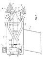
- the schematically illustrated device according to FIG. 1 consists essentially of an illumination device 1, a detection device 2, a microprocessor-controlled control and evaluation electronics 3, a display 4 and a battery 5.
- the said elements are accommodated in an upper part formed as a probe head 6.
- the probe head 6 is provided on the front with a front part 8, which comes to rest on the measurement object M.
- the entire device is designed as an autonomous, portable device and provided with a handle 7. As the measurement object M, areas of the lower or upper jaw 9, 10 together with two teeth 11, 12 are shown.
- the lighting device 1 has, as the actual light source, a light-emitting diode arrangement 14 with a multiplicity of light-emitting diodes 15, of which only three of them are shown schematically.
- the light emitting diodes 14 are arranged on a printed circuit board 16.
- the light-emitting diode arrangement 14 has eight different types of light-emitting diodes which emit light in eight different wavelength ranges.
- the lighting device 1 further comprises an optical fiber bundle 17 into which the light emitted by the light emitting diodes 15 is coupled.
- the optical fiber bundle 17 is divided into two Y-shaped strands 17a, 17b.
- the two strands 17a, 17b of the optical fiber bundle 17 are split at the ends into individual, preferably annularly arranged fibers in order to obtain the most homogeneous possible illumination of the object to be measured M.
- the two optical fiber strands 17a, 17b are followed by lenses 19, 20, which additionally contribute to a uniform illumination of the measurement object M.
- lenses 19, 20 On the light guide fiber strands 17a, 17b downstream lenses 19, 20 follow polarizers 21, 22, which are also shown only schematically.
- a reference mark 23 can be seen, the meaning of which will also be discussed in more detail below.
- a fiber optic fiber bundle 17 for example, a glass rod can be used.
- the detection device 2 is provided with a detection sensor 25 which serves to detect the light reflected by the measurement object M.
- a detection sensor 25 is preferably a black and white CCD chip (Charge Coupled Device) or a black and white CMOS image sensor is used.
- the detection sensor 25 is connected to the electronics 3 via a data line 28. In order to direct the light reflected by the measurement object M to the detection sensor 2, this is preceded by a lens 26.
- a polarizer 27 is arranged, which are tuned to the optical fiber strands 17a, 17b downstream polarizers 20, 22 in such a way that it passes the light emitted by the object to be measured M, while acting as a filter for from the surface of the object to be measured M.
- the polarizer (27) arranged upstream of the detection sensor 25 has a polarization direction rotated by 90 ° relative to the polarizers 20, 22 connected downstream of the optical fiber strands 17a, 17b, or at most no twisted polarization direction, wherein In this case, the polarization is twisted with one or more additional circulator polarizers.
- the device is further provided with a plug connection 31, which is connected via a data line 30 to the electronics 3. Via this plug connection 31, bidirectional data can be transmitted and exchanged. In particular, the measured colorimetric data can be read out via the plug connection 31.
- a plug 33 can be seen, which is connected via a line 32 to the battery and serves to connect a charger. It is understood that the term "battery" is representative of both conventional batteries and all types of rechargeable batteries.
- the light-emitting diode arrangement 14 has eight different types of light-emitting diode which emit visible light in the sense of a monochromator in eight different, narrowband wavelength ranges between approximately 430 and 650 nanometers, wherein the wavelength ranges should be distributed as evenly as possible over the stated range.
- a different number of types of light-emitting diode can be used instead of eight different types of light-emitting diode.
- the number of types of LEDs used depends i.a. their availability and the requirements of colorimetry. Of course, should one of the LED's be available with other or additional wavelength ranges, then the total visible light range between about 380 and 730 nanometers could be covered by a corresponding number of LED types.
- the LEDs 15 are preferably arranged by means of chip-on-board technology annular on the circuit board 16 and electrically connected by means of bonding technology with the corresponding conductor or contact surface.
- a metal core board is used.
- the individual LEDs are mounted and bonded without housing on the circuit board, wherein the entire light emitting diode array by means of a casting material, for example, clear epoxy resin, poured and coupled by means of another mass, such as a permanently elastic silicone gel, optically to the optical fiber bundle 17.
- the diameter of the fiber optic fiber bundle 17 is tuned to the diameter of the light emitting diode array 14 and is less than ten millimeters in the present case.
- the individual high-performance light-emitting diodes are arranged in the center, while the less powerful light-emitting diodes are arranged grouped on the periphery.
- the illumination device 1 is advantageously designed such that not only the measurement object 7 itself, but also the adjacent regions of the upper and lower jaw 6a, 6b are illuminated. Due to the average size of a tooth, an area of at least 10x15 mm, preferably at least 16x22mm, should be illuminated. Due to the translucency of the measurement object, it is important in any case that the illuminated area is larger than the area detected for the determination of the color valence of the measurement object M, ie larger than a single tooth.
- a measurement without illumination is performed first.
- the measurement value present at the detection sensor 25 at this time thus corresponds to the light coupled in from outside into the measurement object M or the detection device 2 (ambient light). So that in the subsequent measurements carried out with illumination, the measured value present at the detection sensor 25 is not falsified by the light coupled in from the outside, this dark value is in each case subtracted from the actual measured value.
- eight measurements are carried out with illumination by the respective light-emitting diode or the respective light-emitting diode group is sequentially driven / so that the measurement object M is illuminated in succession with visible light in eight different wavelength ranges.
- the measured value applied to the detection sensor 25 is detected and stored.
- the respective LED types are energized only for a very short time with power, but with a multiple of the rated current.
- the LEDs are energized only for about 20 milliseconds, but with five to ten times the nominal current specified by the manufacturer. In this way, the desired light intensity can be achieved without the light-emitting diodes 15 being damaged. Since the luminous flux emitted by the light-emitting diodes 15 is subject to or may be subject to certain fluctuations, the measurement of the reference mark 23 will occur with each measurement measured on the detection sensor 25 reflected luminous flux.
- the emitted luminous flux can be calculated and, if necessary, a correction of the measured values can be carried out.
- the correction values are calculated as follows: If a modified light value is measured on the reference surface of the respective reference mark 23, the measurement data are corrected by the factor of the change on the reference surface.
- two reference marks are preferably used. The reference marks are arranged as close as possible to the front part 8 of the probe head 6. In order not to influence the size of the image to be evaluated by the two reference marks in a sustainable and negative manner, the two reference marks are preferably positioned such that they cover only the corner regions of the image to be acquired.
- the measurement object M is displayed visually on the display 4.
- the measurement object M is illuminated sequentially and in very short time intervals in the wavelength ranges of the three primary colors red, green and blue.
- those three types of light emitting diode are sequentially driven, which emit light in the next three wavelengths closest wavelength ranges. From these three primary colors can then computationally a color image assembled and reproduced the measurement object in color on the display, as shown in suggestion.
- the probe head of the device must be aligned with respect to the measurement object such that the optical axis of the device runs exactly perpendicular to the surface of the measurement object.
- the measurement object is a tooth in the mouth of a patient
- the above-mentioned exact alignment of the optical axis is not so easy to accomplish because the operator can not see the tooth during the measurement process.
- Another difficulty is that the teeth are often arranged somewhat obliquely in the mouth of a patient. Since the probe head of the device according to the invention is handled manually, i.
- this problem is taken into account in that a possible angular error in positioning the Probe head 6 is visualized so that the position or orientation of the probe head 6 of the device can be easily corrected before the measurement is performed.
- an extended illumination device is provided in this further exemplary embodiment, of which the essential parts are shown schematically in FIG. 3 in order to project a line pattern onto the surface of the measurement object M at an angle of 45 °. As can be seen from FIG. 2, the parallel lines 34 of the line pattern run vertically on the surface of the measuring object 35.
- the resulting line pattern 34a is on the surface of the measuring object 35 relative to the vertical line pattern 34 generated by a correctly placed probe head 6 , inclined.
- the line pattern 34 or 34a can be made visible on the display 4 (FIG. 1) with the aid of the sensor 26 and the sensor 25. In this way, the operator can correct the position and orientation of the probe head 6.
- the image of the line pattern received by the sensor 25 can be further processed by the control and evaluation unit 3 to calculate the angle error based on the course of the lines 34a projected on the surface of the measurement object.
- the deviation of the course of the lines 34a from the horizontal direction is directly proportional to the deviation of the optical axis of the probe head from the desired direction.
- the control and evaluation unit 3 can provide a statement that allows the operator to correct the position or orientation of the probe head 6.
- an illumination device 1 is already present, which makes it possible to determine the color valence of the measurement object and to illuminate the measurement object at an angle of 45 °.
- this illumination device 1 makes sense to use at least parts of this illumination device 1 to additionally project the line pattern 34 onto the measurement object 35.
- the line pattern 34 is e.g. generated in the range of infrared radiation.
- An alternative illumination device is shown in a schematic side view in FIG. 6 and in a schematic view from above in FIG. 7. It comprises a homogenizer 41, eg a glass rod or a fiber optic bundle, a first deflecting mirror 42, a second deflecting mirror 43, a first lens 44, a second lens 45, a slit diaphragm 46 and a filter 47.
- the radiation path is indicated by the line 48, and the dot-dash line in Fig. 7 symbolizes the plane of symmetry. It is understood that in addition there are the parts and elements required for the measurement of the color valence, which were discussed at the beginning in connection with FIG. 1,
- the illumination device according to FIGS. 6 and 7 shows the following differences:
- the light emitting diode array 14 (not shown in FIGS. 6 and 7) additionally includes at least one other light emitting diode that emits light in the near infrared region, i. with a wavelength of about 850 nm.
- the light which emit this further or this further light emitting diode (s) is likewise coupled into the glass rod or the optical fiber bundle 41.
- a further measurement with illumination by the additional IR light emitting diode or the additional IR light emitting diodes is performed.
- the light fiber bundle 41 is in this embodiment not divided into two strands 17a, 17b as in the embodiment of FIG. 1. Rather, the light beam leaving the optical fiber bundle 41 is deflected by the first deflecting mirror 42 by 90 °.
- the front of the deflecting mirror 42 is provided with a so-called cold light mirror layer. Such a layer acts as a mirror for the visible light, but is transparent to IR light.
- the back of the mirror 42 is provided with a line pattern which reflects infrared radiation.
- the line pattern is projected through the front-side coating of the mirror 42, which is transparent to IR, via the second deflection mirror 43 and the lens 45 onto the measurement object 35.
- the line pattern is aligned so that it extends on the surface of the measurement object in the vertical direction, as indicated in FIGS. 2 and 5.
- an aperture / filter combination 46, 47 is inserted in the light path 48. This is necessary because the reflective line pattern on the back of the mirror 42 is not optically in the right place, resulting in a blurred image of the line pattern on the surface of the device under test.
- the slit diaphragm 46 Through the slit diaphragm 46, the depth of field is increased so far that a sharp image of the line pattern on the surface of the measurement object is ensured.
- slit diaphragm 46 is designed to have no effect on visible light, i. is transparent in order to avoid light losses in the actual colorimetric measurement. This is in turn achieved by a so-called cold light mirror layer on the surface of the slit, but has a central slot.
- visible light can pass unhindered through the aperture / filter combination 45, 46, while the infrared light can only pass through the slot.
- the cold mirror layer is not perfect, then this is not bad or harmless to the measurement because these tracks would be completely blurred.
- the illumination device according to FIGS. 6 and 7 is generally symmetrical with respect to the line 49.
- the projection of the line pattern onto the surface of the measuring object 35 preferably takes place only from one side.
- the arrangement symmetrical with the arrangement shown in FIG. 7 is slightly different.
- the first deflecting mirror 42 has no reflective layer in the form of a line pattern on its rear side. Therefore, no line pattern is projected onto the surface of the measuring object 35 from that side.
- the arrangement 45, 46 is a cold mirror without slot and thus not transparent to infrared light. Consequently, light having a wavelength in the infrared region only reaches the surface of the measuring object 35 from one side, while visible light is projected from both sides onto the surface of the measuring object.
Landscapes
- Physics & Mathematics (AREA)
- Spectroscopy & Molecular Physics (AREA)
- General Physics & Mathematics (AREA)
- Health & Medical Sciences (AREA)
- Life Sciences & Earth Sciences (AREA)
- Chemical & Material Sciences (AREA)
- Analytical Chemistry (AREA)
- Biochemistry (AREA)
- General Health & Medical Sciences (AREA)
- Immunology (AREA)
- Pathology (AREA)
- Investigating Or Analysing Materials By Optical Means (AREA)
Applications Claiming Priority (1)
| Application Number | Priority Date | Filing Date | Title |
|---|---|---|---|
| CH12762004 | 2004-07-29 |
Publications (2)
| Publication Number | Publication Date |
|---|---|
| EP1621857A2 true EP1621857A2 (fr) | 2006-02-01 |
| EP1621857A3 EP1621857A3 (fr) | 2006-04-12 |
Family
ID=35149651
Family Applications (1)
| Application Number | Title | Priority Date | Filing Date |
|---|---|---|---|
| EP05405406A Withdrawn EP1621857A3 (fr) | 2004-07-29 | 2005-06-24 | Appareil pour la détermination d'une couleur d'un corps transparent, notamment des dents |
Country Status (2)
| Country | Link |
|---|---|
| US (1) | US7312874B2 (fr) |
| EP (1) | EP1621857A3 (fr) |
Families Citing this family (9)
| Publication number | Priority date | Publication date | Assignee | Title |
|---|---|---|---|---|
| DE202004015271U1 (de) * | 2004-09-29 | 2006-02-09 | Brose Fahrzeugteile Gmbh & Co. Kg, Coburg | Elektromotor und elektrische Antriebseinheit für Kraftfahrzeuge |
| FR2894666B3 (fr) * | 2005-12-12 | 2008-04-04 | Micro Module Soc Par Actions S | Systeme de mesure optique de la colorimetrie d'un objet |
| TWI390194B (zh) * | 2006-11-10 | 2013-03-21 | Hon Hai Prec Ind Co Ltd | 主機板發光二極體測試裝置及方法 |
| EP1936337B1 (fr) * | 2006-12-21 | 2010-06-02 | X-Rite Europe GmbH | Tête manométrique et dispositif de balayage et dispositif de balayage équipé de celle-ci |
| GB2474701B (en) * | 2009-10-26 | 2014-04-30 | Richard Frank Lawn | A handheld device for measuring the colour properties of objects |
| US9478043B2 (en) * | 2014-01-29 | 2016-10-25 | Abdullaibrahim Abdulwaheed | Measuring teeth whiteness system and method |
| US10432927B2 (en) * | 2014-09-30 | 2019-10-01 | Ningbo Sunny Opotech Co., Ltd. | 3D test chart, adjusting arrangement, forming method and adjusting method thereof |
| US11054562B2 (en) | 2017-08-30 | 2021-07-06 | Gentex Corporation | Polarized illumination systems |
| US10547780B2 (en) | 2018-05-14 | 2020-01-28 | Abdul Abdulwaheed | Body part color measurement detection and method |
Citations (2)
| Publication number | Priority date | Publication date | Assignee | Title |
|---|---|---|---|---|
| EP0928957A2 (fr) | 1998-01-09 | 1999-07-14 | MHT Optic Research AG | Procédé et appareil pour la détermination d'une couleur d'un corps transparent |
| US20030142314A1 (en) * | 2001-05-22 | 2003-07-31 | Xerox Corporation | Angular, azimuthal and displacement insensitive spectrophotometer for color printer color control systems |
Family Cites Families (6)
| Publication number | Priority date | Publication date | Assignee | Title |
|---|---|---|---|---|
| US5241170A (en) * | 1992-02-19 | 1993-08-31 | Itt Corporation | Fiber optic imaging device and methods |
| US5963333A (en) * | 1996-09-12 | 1999-10-05 | Color Savvy Systems Limited | Color sensor |
| US6038024A (en) * | 1998-01-09 | 2000-03-14 | Mht Optic Research | Method and an apparatus for determining the color stimulus specification of an object |
| US6525819B1 (en) * | 1998-09-02 | 2003-02-25 | Pocketspec Technologies Inc. | Colorimeter for dental applications |
| CN1672428B (zh) * | 2002-07-26 | 2010-11-03 | 奥林巴斯株式会社 | 图像处理系统 |
| DE10256188A1 (de) * | 2002-12-02 | 2004-06-24 | Johann Wolfgang Goethe-Universität Frankfurt am Main | Reflexionsspektrometer |
-
2005
- 2005-06-24 EP EP05405406A patent/EP1621857A3/fr not_active Withdrawn
- 2005-07-01 US US11/173,272 patent/US7312874B2/en not_active Expired - Lifetime
Patent Citations (2)
| Publication number | Priority date | Publication date | Assignee | Title |
|---|---|---|---|---|
| EP0928957A2 (fr) | 1998-01-09 | 1999-07-14 | MHT Optic Research AG | Procédé et appareil pour la détermination d'une couleur d'un corps transparent |
| US20030142314A1 (en) * | 2001-05-22 | 2003-07-31 | Xerox Corporation | Angular, azimuthal and displacement insensitive spectrophotometer for color printer color control systems |
Also Published As
| Publication number | Publication date |
|---|---|
| US20060023215A1 (en) | 2006-02-02 |
| US7312874B2 (en) | 2007-12-25 |
| EP1621857A3 (fr) | 2006-04-12 |
Similar Documents
| Publication | Publication Date | Title |
|---|---|---|
| EP0683384B1 (fr) | Dispositif pour déterminer les valeurs de couleur d'un flux lumineux | |
| DE10149780B4 (de) | Einrichtung zur Beleuchtung einer Messfläche und Vorrichtung und Verfahren zur Bestimmung der visuellen Eigenschaften von Körpern | |
| EP0279191B1 (fr) | Dispositif pour la mesure sans contact de la rémission | |
| EP1262751B1 (fr) | Dispositif et procédé d'analyse de lumière | |
| EP0777113A1 (fr) | Procédé et appareil pour la détermination d'une couleur d'un corps transparent | |
| DE2459119C2 (de) | Lichtempfindliche Sortiermaschine | |
| DE19609045C1 (de) | Verfahren und Vorrichtung zur optischen Prüfung eines Holzprüflings | |
| EP0121831A2 (fr) | Dispositif de mesure de particules diffusantes | |
| DE4032327C2 (fr) | ||
| DE2851455C3 (de) | Vorrichtung zur Bestimmung von das Glanzvermögen von Oberflächen charakterisierenden Remissionswerten | |
| DE102009044151A1 (de) | Vorrichtung zur optischen Waferinspektion | |
| DE2739793A1 (de) | Kolorimeter | |
| DE3217258C2 (de) | Vorrichtung zum Nachweis eines Agglutinationsmusters | |
| EP1621857A2 (fr) | Appareil pour la détermination d'une couleur d'un corps transparent, notamment des dents | |
| DE10156434A1 (de) | Videoendoskop und Videoendoskopsystem | |
| DE4434203C2 (de) | Vorrichtung und Verfahren zum Messen visueller Eigenschaften von Oberflächen | |
| EP2513874B1 (fr) | Détecteur pour vérifier des documents de valeur | |
| DE10000030A1 (de) | Kamerasystem für die Bearbeitung von Dokumenten | |
| DE3421577A1 (de) | Geraet zur reflexionsmessung an farbigen objekten | |
| EP0735501B1 (fr) | Arrangement de détecteurs de couleur pour lire des marquages en couleur | |
| DE10156804B4 (de) | Optische Meßvorrichtung für Teststreifen | |
| DE19610393A1 (de) | Verfahren und Vorrichtung zum Identifizieren und/oder Klassifizieren von Edelsteinen mit einem Spektrometer | |
| DE10137043A1 (de) | Vorrichtung zur Untersuchung von Wertdokumenten | |
| DE3239995C2 (de) | Vorrichtung zum Erkennen von Dokumenten | |
| WO1994025849A1 (fr) | Systeme permettant de mesurer ponctuellement la luminance de reflexion de surfaces |
Legal Events
| Date | Code | Title | Description |
|---|---|---|---|
| PUAI | Public reference made under article 153(3) epc to a published international application that has entered the european phase |
Free format text: ORIGINAL CODE: 0009012 |
|
| AK | Designated contracting states |
Kind code of ref document: A2 Designated state(s): AT BE BG CH CY CZ DE DK EE ES FI FR GB GR HU IE IS IT LI LT LU MC NL PL PT RO SE SI SK TR |
|
| AX | Request for extension of the european patent |
Extension state: AL BA HR LV MK YU |
|
| PUAL | Search report despatched |
Free format text: ORIGINAL CODE: 0009013 |
|
| AK | Designated contracting states |
Kind code of ref document: A3 Designated state(s): AT BE BG CH CY CZ DE DK EE ES FI FR GB GR HU IE IS IT LI LT LU MC NL PL PT RO SE SI SK TR |
|
| AX | Request for extension of the european patent |
Extension state: AL BA HR LV MK YU |
|
| 17P | Request for examination filed |
Effective date: 20061002 |
|
| 17Q | First examination report despatched |
Effective date: 20061107 |
|
| AKX | Designation fees paid |
Designated state(s): AT BE BG CH CY CZ DE DK EE ES FI FR GB GR HU IE IS IT LI LT LU MC NL PL PT RO SE SI SK TR |
|
| STAA | Information on the status of an ep patent application or granted ep patent |
Free format text: STATUS: THE APPLICATION IS DEEMED TO BE WITHDRAWN |
|
| 18D | Application deemed to be withdrawn |
Effective date: 20140103 |