EP1621970A2 - Appareil électronique avec dispositif de refroidissement - Google Patents
Appareil électronique avec dispositif de refroidissement Download PDFInfo
- Publication number
- EP1621970A2 EP1621970A2 EP05102227A EP05102227A EP1621970A2 EP 1621970 A2 EP1621970 A2 EP 1621970A2 EP 05102227 A EP05102227 A EP 05102227A EP 05102227 A EP05102227 A EP 05102227A EP 1621970 A2 EP1621970 A2 EP 1621970A2
- Authority
- EP
- European Patent Office
- Prior art keywords
- heat radiation
- heat
- cooling device
- circulation path
- pump unit
- Prior art date
- Legal status (The legal status is an assumption and is not a legal conclusion. Google has not performed a legal analysis and makes no representation as to the accuracy of the status listed.)
- Withdrawn
Links
Images



Classifications
-
- G—PHYSICS
- G06—COMPUTING OR CALCULATING; COUNTING
- G06F—ELECTRIC DIGITAL DATA PROCESSING
- G06F1/00—Details not covered by groups G06F3/00 - G06F13/00 and G06F21/00
- G06F1/16—Constructional details or arrangements
- G06F1/20—Cooling means
- G06F1/203—Cooling means for portable computers, e.g. for laptops
Definitions
- One embodiment of the invention relates to an electronic apparatus with a cooling device in which liquid coolant is circulated for cooling a heat generating element.
- the amount of heat generated during operations is increasing, accompanying with faster speed operation and more multifunctional device. If the temperature of the CPU becomes too high, the CPU processing speed may decrease and there may be errors in the CPU operation.
- cooling device in which liquid coolant (hereinafter “coolant”) such as antifreeze or water, is circulated in order to increase cooling performance for the CPU. Heat recovered from the CPU is radiated outside the electronic apparatus.
- coolant liquid coolant
- the above-described cooling device comprises a heat receiving member for receiving heat from the CPU, a heat radiation member for radiating heat received by the heat receiving member, a coolant path for guiding the heat received by the heat receiving member on to the heat radiation member, and a fan for sending air to the heat radiation member and the like.
- the heat radiation member comprises a conduit such as a pipe for guiding the coolant whose temperature has been increased by the heat received by the heat receiving member and a fan or metal plate or the like for reducing the temperature of the coolant which flows in the pipes.
- Japanese Patent Application Publication (KOKAI) No. 2002-99356 discloses an electronic apparatus with such the cooling device.
- the semiconductor package in this electronic apparatus namely the casing that houses the heat generating element, is thermally connected to a circulation path in which coolant is circulated, and the circulation path is elongated into the display unit for cooling.
- This electronic apparatus also includes a cooling fan.
- the heat generated by the heat generating element may exceed the cooling ability of the cooling device described in the reference when the speed of a CPU is faster and faster.
- a cooling device comprising:
- a cooling device comprises a heat receiving member to receive heat from a heat generating element, a circulation path thermally connected to the heat receiving member, the circulation path carrying coolant which the heat is transferred through the heat receiving member, a pump unit to circulate the coolant inside the circulation path, a first heat radiation mechanism including a first heat radiation member thermally connected to the circulation path, and a first fan which sends air toward the first heat radiation member, and a second heat radiation mechanism including a second heat radiation member thermally connected to the circulation path, and a second fan which sends air toward the second heat radiation member.
- FIG. 1 shows a portable computer 1 as an electronic apparatus to which an embodiment of this invention is applied.
- the portable computer 1 comprises a body unit 2 and a display unit 3.
- the body unit 2 has a casing 4 that is formed in a flat, box-configuration.
- a keyboard 5, which is used for inputting numbers and letters, is provided at a prescribed position exposed on the casing 4.
- the casing 4 may, for example, be made of a metallic material such as a magnesium alloy.
- the cooling device 11, which is described hereinafter using FIGS. 2 and 3, is provided at a prescribed position inside the casing 4.
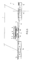
- FIG. 2 shows the portable computer 1 placed on a surface 111 such as a desk that is a substantially flat surface.
- a side portion in the casing 4 of the portable computer 1 is cut away in FIG. 2, and a fan of the cooling device 11 may be seen through the cut portion.
- the casing 4 has a prescribed incline such that the rear edge 4a of the casing 4 is positioned higher than the front edge 4b of the casing 4.
- a user operates a front edge side of the display unit 3, right side in FIG. 2, and rotates the display unit 3 about an axis of hinge (not shown) arranged in a rear edge side of the display unit 3, left side in FIG. 2.
- the cooling device 11 is accommodated at the rear edge 4a side of the casing 4.
- a part of a fan of the cooling device 11 and a part of a radiator that is constructed integrally with the fan is exposed.
- a cooling part cover 6 which is formed independently from the casing 4 covers the cooling device 11 and around it.
- the cooling part cover 6 also functions as a leg for causing the above-described incline of the casing 4.
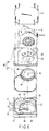
- FIG. 3 shows the cooling device 11 partly shown in FIG. 2 when viewed from the top.
- the cooling device 11 comprises a pump unit 13 positioned between the first and second fans 12a and 12b that are disposed so as to be substantially horizontally symmetrical when viewed from the top. At least a part of the exterior of the pump unit 13 is disposed at a position which crosses a hypothetical line H which crosses both the central axis of the first and second fans 12a and 12b, when the pump unit 13 is viewed from the top.
- First and second heat radiation fins 14a and 14b are heat radiation members to radiate heat transferred, and arranged around each of the first fans and second fans 12a and 12b respectively. Placement of the fans 12a and 12b substantially horizontally symmetrical to each other, in the case where a plurality of fans is used in the cooling device of the electronic apparatus, contributes to drowning vibration generated from the rotation of each of the fans 12a, 12b and controls undesired resonance in the casing 4.
- Each of the first and second heat radiation fins 14a and 14b is thermally connected to a coolant circulation path 15 that is a conduit and in which liquid coolant (simply “coolant” hereinafter) flows.
- the pump unit 13 connects to the coolant circulation path 15 to circulate the coolant.
- the coolant circulation path 15 has two parts, namely a first flow path connected to the first heat radiation fins 14a and a second flow path connected to the second heat radiation fins 14b.
- the coolant circulation path 15 may be formed of a pipe or tube with high thermal conductivity and made of copper, brass, or stainless steel with a cross-section configuration that may be circular or non-circular. It is contemplated that a flexible tube such a rubber tube or the like may also be used.
- the coolant may be antifreeze or water. Under the circumstances described above, radiation of heat conveyed by the coolant through the first and second heat radiation fins 14a and 14b may be performed efficiently.
- a mount base 11a which is a supporting member, is a metal plate forming a vital portion of the cooling device 11 and supports the first and second heat radiation fins 14a and 14b and the coolant circulation path 15, for example, soldered or molded thereon.
- a substance such as silicon grease or the like may be provided between the first and second heat radiation fins 14a and 14b, the coolant circulation path 15, and the mount base 11a if necessary, in order to thermally improve the connection efficiency between both parts. It is to be noted that in the case where the coolant circulation path 15 is a tube made of rubber or the like, mounting attachments and the like may be used for mounting.
- Connecting portions 15a and 15b connect the pump unit 13 to a part of the coolant circulation path 15, and are separated from the mount base 11a.
- the connecting portion 15a connects discharge portion of the pump unit 13 to the coolant circulation path 15, and the connecting portion 15b connects suction portion of the pump unit 13 to the coolant circulation path 15.
- the connecting portions 15a and 15b may be covered by a tube having portions made of rubber or a rubber tube having a belt-like piece of metal at the outer periphery, and a flexible tube or the like which may deform into a suitably selected configuration may be used.
- the pump unit 13 may be disposed at a more suitable position that corresponds to the position of the heat generating element.
- the connecting portions 15a and 15b for connection between the pump unit 13 and the coolant circulation path 15 it may be easier to separate the pump unit 13 of the cooling device 11 from the heat generating element such as central processing unit (hereinafter "CPU") or TC chip, namely such structure contributes to improve efficiency of disassembly and/or replacement.
- CPU central processing unit
- TC chip namely such structure contributes to improve efficiency of disassembly and/or replacement.
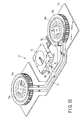
- FIG. 4 illustrates one of heat radiation mechanisms of the cooling device 11, which includes one of the first and second heat radiation fins 14a (or 14b), and one of the first and second cooling fans 12a (or 12b) which are respectively positioned and linked with the heat radiation fins 14a (or 14b).
- the structure of both of the heat radiation mechanisms, combination of the first heat radiation fins 14a and the first fan 12a and combination of the second heat radiation fins 14b and the second fan 12b, are substantially the same and thus only one which is combination of the first heat radiation fin 14a and the first fan 12a, will be described.
- the first heat radiation fins 14a have a heat radiating body 61 that is formed in an arc-like or circular configuration from a member having high thermal conductivity such as copper or aluminum.
- An impeller 62 for generating airflow is positioned substantially at the center of the arc or circle of the heat radiating body 61, as the first fans 12a.
- Each of the impellers 62 is rotated in a prescribed direction by a motor portion that is not described in detail.
- the heat radiating body 61 and the impeller 62 respectively may have the same configuration or may have a symmetrical configuration.
- the coolant circulation path 15 is in the vicinity of a prescribed location on the heat radiating body 61 or in contact with it such as the arc-like configuration or the cylindrical portion of the circular configuration.
- FIG. 4b shows the coolant circulation path 15 when viewed from the lateral surface direction.
- the coolant circulation path 15 In the region where the coolant circulation path 15 physically contacts or comes close to the heat radiating body 61, the coolant circulation path 15 has a flat cross-section along the width of the heat radiating body 61, length in the diametrical direction.
- the coolant circulation path 15 and the heat radiating body 61 are preferably thermally connected by soldering or molding.
- the pump unit 13 is thermally connected with a CPU 22, namely an IC chip 24 of the CPU 22, which is substantially disposed at the center on the top of a printed circuit board 21, via silicone grease 25, or a heat transferring sheet.
- the CPU 22 is a main control circuit and also a heat generating element which is provided on the print circuit board 21 arranged in the casing 4.
- the pump unit 13 and the first and second fans 12a and 12b are, depending on the IC chip 24's position, offset by a predetermined amount when viewed from a direction in an orthogonal direction to the plane defined by the hypothetical line H which crosses the central axis of each of the fans 12a and 12b and the axis line of the fans 12a and 12b. That is, the pump unit 13 may be provided at a position, which corresponds to the surface at the opposite side of the fans 12a and 12b which are positioned at one surface of the mount base 11a.
- the IC chip 24 Due to increased processing speed and performance of multiple functions, the IC chip 24 generates a large amount of heat during operation and the temperature increases rapidly. Thus, in order for the IC chip 24 to operate continuously and stably, effective cooling, namely effective heat radiation is needed.
- the cooling method may be air cooling, but as the amount of heat generated increases, radiating heat carried via a coolant, which is circulated, is advantageous in obtaining highly effective cooling.
- the pump unit 13 comprises a pump housing 31 that functions as a heat receiving member for receiving heat generated by the CPU 22 which is a part of the IC chip 24.
- the pump housing 31 comprises a housing body 32 and a top cover 33.
- the housing body 32 has a flat box-like configuration of a size that may cover the entire IC chip 24, and is formed of a material having high thermal conductivity such as an aluminum alloy.
- the housing body 32 has a recess portion 34 that is open at the side opposite the side where the IC chip 24 contacts the housing body 32.
- the lower surface of bottom wall 35 in FIG. 6, namely the lower outer surface 36 of the housing body 32, is in contact with the IC chip 24 via silicone grease 25 or the like. Therefore, the lower outer surface 36 functions as a heat receiving member that may receive much of the heat generated by the IC chip 24.
- the top cover 33 may be made of a resin and should be resistant to the coolant, and should tightly seal the recess portion 34 so as to prevent from leakage of the coolant when the opening end thereof comes in contact with the recess portion 34.
- a ring-shaped partition wall 37 partitions the inside of the pump housing 31 into a pump chamber 38 and a reserve tank 39.
- the reserve tank 39 is positioned around the pump chamber 38 for collecting coolant.
- the partition wall 37 is formed so as to be substantially perpendicular to the bottom wall 35 of the housing body 32.
- a channel 40 which makes movement of the coolant between the pump chamber 38 and the reserve tank 39 possible, is formed in the partition wall 37.
- the housing body 32 has a suction tube 41 and a discharge tube 42 which are integrally formed and directed outwards with respect to the recess portion 34.
- One end of the suction tube 41 connects to the connecting portion 15b of FIG. 3, and one end of the discharge tube 42 connects to the connecting portion 15a of FIG. 3.
- the other end of the suction tube 41 is connected to the inside of the reserve tank 39, and opposes the channel 40. As shown in FIG. 7, a space 43 for vapor-liquid separation is formed between the downstream end of the suction tube 41 and the channel 40.
- the other end of the discharge tube 42 is connected to the pump chamber 38 via the partition wall 37.
- a disc-shaped impeller 44 is accommodated in the pump chamber 38 of the pump housing 31.
- the impeller 44 has a rotation axle 45 in the rotation center portion.
- the rotation axle 45 rotates between the bottom wall surface 35 of the housing body 32 and the top cover 33.
- the pump housing 31 includes a motor 46 for rotating the impeller 44.
- the motor 46 comprises a rotor 47 and a stator 48.
- the rotor 47 is fixed at a predetermined position on the impeller 44, and in the case of the example in FIG. 6 it is fixed above the impeller 44 so as to be coaxial with respect to the impeller 44, and is accommodated in the pump chamber 38 along with the impeller 44.
- a magnet 49 which is formed such that a plurality of N poles and a plurality of S poles intersect, is fixed inside the rotor 47. That is, the impeller 44, the rotor 47 and the magnet 49 may rotate about the rotation axle 45.
- the stator 48 is formed at a predetermined position on the top cover 33, and is positioned in the specified recess 50 so as to be capable of coming close to the magnet 49 of the rotor 47.
- the stator 48 is positioned inside the rotor 47 so as to be coaxial with the rotor 47. That is, the external portion in the circumferential direction of the stator 48 opposes the magnet 49 when provided via the recess 50 of the top cover 33. Because the rotor 47, the stator 48 and the magnet 49 are arranged in this manner, an outer ring rotation type motor 46 may be defined.
- the motor 46 and the pump chamber 38 are formed so as to be offset from the center of the pump unit 13.
- a drive circuit board 51 for operating the motor 46 is arranged above the top cover 33.
- the drive circuit board 51 is capable of supplying a predetermined drive current to the stator 48.
- a current of a prescribed size is supplied to the stator 48. This causes the stator 48 to generate a rotating magnetic field in the circumferential direction of the stator 48, and then attraction and repulsion are alternately repeated between the stator 48 and the magnet 49 of the rotor 47. Consequently, this generates torque along the circumferential direction of the rotor 47 between the stator 48 and the magnet 49, and the impeller 44 rotates in a prescribed direction.
- the power source line 52 which supplies current for operating the motor 46 connects to the position of the rotation center of the motor 46. This is a position that is separated from the rotation shaft 45 of the impeller 44 as well as the suction tube 41 and the discharge tube 42, and that is offset from the center of the pump unit 13. That is, when a prescribed current is supplied to the drive circuit board 51, the current supply portion 51a is positioned at a position or the vicinity thereof, which is the furthest distance away from regions which the coolant contact, such as the pump chamber 38, the reserve tank 39 and the suction tube 41 and the discharge tube 42 of the pump unit 13, in order to increase insulation. Thus, insulation of the pump unit 13, which circulates liquid coolant, increases user safety.
- a back plate 53 is fixed by a plurality of fastening elements (e.g., screws) to the top cover 33.
- the back plate 53 shields the stator 48 and the drive circuit board 51.
- the pump unit 13 is positioned on the printed circuit board 21 so as to cover the entire region of the top portion of the IC chip 24 of the CPU 22.
- the pump unit 13 is fixed along with the print circuit board 21 to boss portions 4c formed in advance which are directed from the casing 4 toward positions corresponding to the four corners of the pump housing 31 of FIG. 8.
- the pump unit 13 and the print circuit board 21 are fixed at a prescribed position on the casing 4, and the outer surface 36 of the housing body 32 of the pump unit 13, which is the heat receiving member, is thermally connected with the IC chip 24 of the CPU 22 such that heat conduction is ensured. That is, the heat that is generated and released from the IC chip 24 is transferred to the metallic portion of the outer circumference, namely the outer surface 36 of the housing body 32 of the pump unit 13.
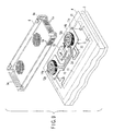
- the cooling device 11 is set in the opening 4d formed in the back surface of the casing 4.
- the pump unit 13 is positioned in the vicinity of the IC chip 24 of the print circuit board 21 that is exposed in advance at a prescribed position in the casing 4.
- the outer surface 36 of the pump unit 13 thermally connects to the IC chip 24 so as to ensure heat releasing.
- mount base 11a of the cooling device 11 may have the function of supplementing the rigidity and strength of the casing 4.
- the heat from the IC chip of 9 is transferred to the pump housing 31 through the outer surface 36 of the housing body 32 of the pump unit 13.
- the heat transferred to the pump housing 31 is dispersed to the coolant, liquid, contained in the pump chamber 38 and the reserve tank 39 of FIG. 6, and thereby collected.
- the operation of motor 46 of FIG. 6 is actuated simultaneously with the flow of current to the portable computer 1 accompanying with power on thereof. Then, the coolant contained in the pump chamber 38 and the reserve tank 39 of FIG. 6 circulates in the cooling circulation path 15. That is, as shown in FIG. 6 by supplying a prescribed amount of drive current from the drive circuit board 51 to the stator 48, torque is generated between the stator 48 and the magnet 49 of the rotor 47, and the rotor 47 rotates together with the impeller 44. As a result, the coolant in the pump chamber 38 of FIG. 6 is pressurized and a prescribed amount of coolant is supplied to the coolant circulation path 15 from the discharge tube 42.
- the coolant that is supplied to the coolant circulation path 15 carries the heat transferred from the IC chip 24 of FIG. 9, and is cooled by airflow from the first fan 12a in the vicinity of the first heat radiation fins 14a.
- the coolant, which is cooled in the vicinity of the first heat radiation fins 14a, is cooled by airflow from the second fan 12b in the vicinity of the second heat radiation fins 14b through the coolant circulation path 15.
- the airflow from the fans 12a and 12b respectively absorbs the heat of vaporization from the corresponding the first and second heat radiation fins 14a and 14b, and consequently, the temperature of the coolant flowing in the coolant circulation path 15 is reduced and then the airflow is blown out from almost the entire circumference of the first and second heat radiation fins 14a and 14b through the slit 6a in the front, rear and left and right walls of the cooling portion cover 6 as shown in FIG. 9, to the outside of casing 4 and the cooling portion cover 6.
- undesired high temperature airflow namely, remaining airflow whose temperature is high, is reduced.
- the characteristics of the IC chip 24 may be prevented from becoming unstable, and operational defects may be prevented.
- the airflow which is absorbed by the heat of vaporization from the respective first and second heat radiation fins 14a and 14b of the cooling device 11 is discharged substantially parallel to the width direction of the casing 4 via the cooling portion cover 6 in a state in which it protrudes beyond the bottom portion of the casing 4.
- the airflow may not be obstructed by the surface 111 to decrease cooling efficiency.
- the air bubbles are separated and removed from the coolant in the reserve tank 39.
- the coolant that is returned to the reserve tank 39 is guided to the pump chamber 38 via the channel 40, and re-pressurized and sent to the coolant circulation path 15.
- heat from the IC chip 24 or the other heat generating element that is received at the outer surface 36 of the pump unit 13 is sequentially discharged by airflow from the fan provided corresponding to the vicinity of the first and second heat radiation fins 14a and 14b using the coolant circulated by the pump unit 13.
- the temperature increase of the IC chip 24 or the other heat generating element is maintained such that the temperature may be within a prescribed permissible range. It is to be noted that because the coolant circulation path 15 is thermally connected to the mount base 11a, which is made of a metal that is effective in radiating heat, the temperature of the coolant flowing in coolant circulation path 15 is also lowered and cooled while being circulated in the coolant circulation path 15.
- the present invention is not to be limited by the above-described embodiment, and various modification may be made within the scope of the invention.
- there are two sets of the heat radiation fins and the fan on either side of the pump unit but three sets or more may be provided.
- the third set of heat radiation fins and the fan may be integrally provided with the pump unit.
- coolant circulation path which contacts, or is in the vicinity of the heat radiation fins may be at the inner diameter side or the outer diameter side of the heat radiating body of the heat radiation fins, and may be arranged around two or more circumferences.
- a heat receiving member may be arranged separately from the pump unit 13.
- the cooling device 11 may have independent heat receiving member at some portion in the coolant circulation path 15, for example between the pump unit 13 and the first cooling mechanism.
- the coolant circulation path may have joints at suitably selected positions.
Landscapes
- Engineering & Computer Science (AREA)
- Theoretical Computer Science (AREA)
- Computer Hardware Design (AREA)
- Human Computer Interaction (AREA)
- Physics & Mathematics (AREA)
- General Engineering & Computer Science (AREA)
- General Physics & Mathematics (AREA)
- Cooling Or The Like Of Electrical Apparatus (AREA)
- Cooling Or The Like Of Semiconductors Or Solid State Devices (AREA)
Applications Claiming Priority (1)
| Application Number | Priority Date | Filing Date | Title |
|---|---|---|---|
| JP2004224722A JP2006049382A (ja) | 2004-07-30 | 2004-07-30 | 冷却装置及び電子機器 |
Publications (2)
| Publication Number | Publication Date |
|---|---|
| EP1621970A2 true EP1621970A2 (fr) | 2006-02-01 |
| EP1621970A3 EP1621970A3 (fr) | 2007-02-21 |
Family
ID=35355121
Family Applications (1)
| Application Number | Title | Priority Date | Filing Date |
|---|---|---|---|
| EP05102227A Withdrawn EP1621970A3 (fr) | 2004-07-30 | 2005-03-21 | Appareil électronique avec dispositif de refroidissement |
Country Status (4)
| Country | Link |
|---|---|
| US (1) | US20060023421A1 (fr) |
| EP (1) | EP1621970A3 (fr) |
| JP (1) | JP2006049382A (fr) |
| CN (1) | CN1728043A (fr) |
Cited By (4)
| Publication number | Priority date | Publication date | Assignee | Title |
|---|---|---|---|---|
| CN101364576B (zh) * | 2008-09-19 | 2011-07-20 | 秦彪 | 半导体电子器件散热器 |
| US20230397362A1 (en) * | 2022-06-02 | 2023-12-07 | Inventec (Pudong) Technology Corporation | Heat dissipation structure |
| US12075594B2 (en) | 2022-06-02 | 2024-08-27 | Inventec (Pudong) Technology Corporation | Heat dissipation structure |
| US12213277B2 (en) | 2022-06-02 | 2025-01-28 | Inventec (Pudong) Technology Corporation | Air cooling system |
Families Citing this family (18)
| Publication number | Priority date | Publication date | Assignee | Title |
|---|---|---|---|---|
| JP4056504B2 (ja) | 2004-08-18 | 2008-03-05 | Necディスプレイソリューションズ株式会社 | 冷却装置及びこれを備えた電子機器 |
| JP2007242822A (ja) * | 2006-03-08 | 2007-09-20 | Hitachi Ltd | 電子機器用の冷却装置 |
| JP2007240075A (ja) * | 2006-03-09 | 2007-09-20 | Matsushita Electric Ind Co Ltd | 熱搬送デバイスと、それを用いた液冷システム |
| JP4742965B2 (ja) * | 2006-04-18 | 2011-08-10 | パナソニック株式会社 | 熱搬送デバイスと、それを用いた液冷システム |
| JP5283836B2 (ja) | 2006-07-25 | 2013-09-04 | 富士通株式会社 | 液冷ユニット用受熱器および液冷ユニット並びに電子機器 |
| JP2008027370A (ja) * | 2006-07-25 | 2008-02-07 | Fujitsu Ltd | 電子機器 |
| JP2008027374A (ja) * | 2006-07-25 | 2008-02-07 | Fujitsu Ltd | 液冷ユニット用受熱器および液冷ユニット並びに電子機器 |
| JP4781929B2 (ja) * | 2006-07-25 | 2011-09-28 | 富士通株式会社 | 電子機器 |
| JP5133531B2 (ja) * | 2006-07-25 | 2013-01-30 | 富士通株式会社 | 液冷ユニット用熱交換器および液冷ユニット並びに電子機器 |
| JP5148079B2 (ja) * | 2006-07-25 | 2013-02-20 | 富士通株式会社 | 液冷ユニット用熱交換器および液冷ユニット並びに電子機器 |
| JP4842040B2 (ja) | 2006-07-25 | 2011-12-21 | 富士通株式会社 | 電子機器 |
| JP2009003665A (ja) * | 2007-06-21 | 2009-01-08 | Hitachi Ltd | Fan制御方法 |
| CN101369562B (zh) * | 2008-06-18 | 2012-10-31 | 秦彪 | 板式热管散热器及其应用 |
| CN101290531B (zh) * | 2008-06-18 | 2013-04-10 | 秦彪 | 便携式计算机 |
| TWI468100B (zh) * | 2011-01-31 | 2015-01-01 | Inventec Corp | 行動運算裝置 |
| JP2014132388A (ja) * | 2013-01-04 | 2014-07-17 | Sony Corp | 電子機器のフレーム構造 |
| JP6236942B2 (ja) * | 2013-07-10 | 2017-11-29 | 富士通株式会社 | 配管接続構造、冷却システム、及び、電子機器 |
| JP7573073B1 (ja) | 2023-07-06 | 2024-10-24 | レノボ・シンガポール・プライベート・リミテッド | 電子機器 |
Family Cites Families (51)
| Publication number | Priority date | Publication date | Assignee | Title |
|---|---|---|---|---|
| US5268817A (en) * | 1990-04-27 | 1993-12-07 | Kabushiki Kaisha Toshiba | Portable computer with keyboard and having display with coordinate input tablet rotatably mounted to face either toward or away from keyboard when closed over keyboard |
| JP3255818B2 (ja) * | 1995-03-20 | 2002-02-12 | カルソニックカンセイ株式会社 | 電子部品用冷却装置 |
| JP3258198B2 (ja) * | 1995-04-28 | 2002-02-18 | 株式会社東芝 | 回路モジュールの冷却装置およびこの冷却装置を有する携帯形電子機器 |
| US6094180A (en) * | 1996-04-05 | 2000-07-25 | Fakespace, Inc. | Gimbal-mounted virtual reality display system |
| US5772500A (en) * | 1996-12-20 | 1998-06-30 | Symbios, Inc. | Compact ventilation unit for electronic apparatus |
| US6005767A (en) * | 1997-11-14 | 1999-12-21 | Vadem | Portable computer having articulated display |
| US20020053421A1 (en) * | 1997-09-10 | 2002-05-09 | Kabushiki Kaisha Toshiba | Heat dissipating structure for electronic apparatus |
| KR100286375B1 (ko) * | 1997-10-02 | 2001-04-16 | 윤종용 | 전자 시스템의 방열장치 및 방열장치가 사용된 컴퓨터 시스템 |
| US6464195B1 (en) * | 1997-12-04 | 2002-10-15 | Raymond Hildebrandt | Ergonomic mounting for computer screen displays |
| JP3366244B2 (ja) * | 1998-02-04 | 2003-01-14 | 富士通株式会社 | 電子機器 |
| US6282082B1 (en) * | 1998-07-31 | 2001-08-28 | Qubit, Llc | Case for a modular tablet computer system |
| US6377452B1 (en) * | 1998-12-18 | 2002-04-23 | Furukawa Electric Co., Ltd. | Heat pipe hinge structure for electronic device |
| US6483445B1 (en) * | 1998-12-21 | 2002-11-19 | Intel Corporation | Electronic device with hidden keyboard |
| GB2348459B (en) * | 1999-03-27 | 2003-03-19 | Ibm | Lid restraint for portable computer |
| US6231371B1 (en) * | 1999-06-25 | 2001-05-15 | Hewlett-Packard Company | Docking station for multiple devices |
| JP3283853B2 (ja) * | 1999-09-17 | 2002-05-20 | 米沢日本電気株式会社 | ドッキングステーション |
| US6166907A (en) * | 1999-11-26 | 2000-12-26 | Chien; Chuan-Fu | CPU cooling system |
| US6196850B1 (en) * | 2000-02-10 | 2001-03-06 | International Business Machines Corporation | Rotatable docking station for an electronic device |
| US6418017B1 (en) * | 2000-03-30 | 2002-07-09 | Hewlett-Packard Company | Heat dissipating chassis member |
| US6430038B1 (en) * | 2000-04-18 | 2002-08-06 | Hewlett-Packard Company | Computer with articulated mechanism |
| US6437973B1 (en) * | 2000-04-18 | 2002-08-20 | Hewlett-Packard Company | Modular mechanism for movable display |
| US6313990B1 (en) * | 2000-05-25 | 2001-11-06 | Kioan Cheon | Cooling apparatus for electronic devices |
| JP3302350B2 (ja) * | 2000-06-29 | 2002-07-15 | 株式会社東芝 | 電子機器 |
| US6296048B1 (en) * | 2000-09-08 | 2001-10-02 | Powerwave Technologies, Inc. | Heat sink assembly |
| JP2002099356A (ja) * | 2000-09-21 | 2002-04-05 | Toshiba Corp | 電子機器用冷却装置および電子機器 |
| US6396687B1 (en) * | 2000-10-13 | 2002-05-28 | Dell Products, L.P. | Rotating portable computer docking station |
| JP3607608B2 (ja) * | 2000-12-19 | 2005-01-05 | 株式会社日立製作所 | ノート型パソコンの液冷システム |
| US6717798B2 (en) * | 2001-03-22 | 2004-04-06 | Intel Corporation | Docking digital picture displays |
| US20020141159A1 (en) * | 2001-03-29 | 2002-10-03 | Bloemen James Andrew | Sealed and passively cooled telecommunications customer service terminal |
| FR2827115B1 (fr) * | 2001-07-06 | 2003-09-05 | Alstom | Coffre pour convertisseur de puissance |
| TW558611B (en) * | 2001-07-18 | 2003-10-21 | Matsushita Electric Industrial Co Ltd | Small pump, cooling system and portable equipment |
| US6480373B1 (en) * | 2001-07-24 | 2002-11-12 | Compaq Information Technologies Group, L.P. | Multifunctional foldable computer |
| US6873521B2 (en) * | 2001-07-24 | 2005-03-29 | Hewlett-Packard Development Company, L.P. | Multiple environment foldable computer |
| JP4512296B2 (ja) * | 2001-08-22 | 2010-07-28 | 株式会社日立製作所 | 可搬型情報処理装置の液冷システム |
| TW577578U (en) * | 2001-08-24 | 2004-02-21 | Uniwill Comp Corp | Heat dissipation device of low flow resistance for notebook computer |
| JP2003078270A (ja) * | 2001-09-07 | 2003-03-14 | Hitachi Ltd | 電子装置 |
| JP3946018B2 (ja) * | 2001-09-18 | 2007-07-18 | 株式会社日立製作所 | 液冷却式回路装置 |
| US6981543B2 (en) * | 2001-09-20 | 2006-01-03 | Intel Corporation | Modular capillary pumped loop cooling system |
| JP2003223238A (ja) * | 2002-01-28 | 2003-08-08 | Internatl Business Mach Corp <Ibm> | コンピュータ装置、モニタユニットおよび対面ユニットの支持構造物 |
| US6856506B2 (en) * | 2002-06-19 | 2005-02-15 | Motion Computing | Tablet computing device with three-dimensional docking support |
| US6788530B2 (en) * | 2002-09-24 | 2004-09-07 | International Business Machines Corporation | User friendly computer equipment, monitor unit, and monitor unit setting base |
| JP2004139187A (ja) * | 2002-10-15 | 2004-05-13 | Toshiba Corp | 電子機器 |
| TW545104B (en) * | 2002-11-28 | 2003-08-01 | Quanta Comp Inc | Cooling apparatus |
| TWI278273B (en) * | 2002-12-13 | 2007-04-01 | Arima Computer Corp | Heat dissipation device for electronic component |
| JP2004348650A (ja) * | 2003-05-26 | 2004-12-09 | Toshiba Corp | 電子機器 |
| US7035090B2 (en) * | 2003-09-04 | 2006-04-25 | Kabushiki Kaisha Toshiba | Interlocking mechanism for a display |
| JP2005107122A (ja) * | 2003-09-30 | 2005-04-21 | Toshiba Corp | 電子機器 |
| JP2005190316A (ja) * | 2003-12-26 | 2005-07-14 | Toshiba Corp | 電子機器 |
| JP2005315156A (ja) * | 2004-04-28 | 2005-11-10 | Toshiba Corp | ポンプおよびポンプを備える電子機器 |
| JP2005344562A (ja) * | 2004-06-01 | 2005-12-15 | Toshiba Corp | ポンプ、冷却装置および冷却装置を有する電子機器 |
| JP2006242479A (ja) * | 2005-03-03 | 2006-09-14 | Toshiba Corp | 冷却装置及び電子機器 |
-
2004
- 2004-07-30 JP JP2004224722A patent/JP2006049382A/ja active Pending
-
2005
- 2005-02-04 US US11/052,501 patent/US20060023421A1/en not_active Abandoned
- 2005-03-21 EP EP05102227A patent/EP1621970A3/fr not_active Withdrawn
- 2005-04-22 CN CNA2005100677075A patent/CN1728043A/zh active Pending
Cited By (5)
| Publication number | Priority date | Publication date | Assignee | Title |
|---|---|---|---|---|
| CN101364576B (zh) * | 2008-09-19 | 2011-07-20 | 秦彪 | 半导体电子器件散热器 |
| US20230397362A1 (en) * | 2022-06-02 | 2023-12-07 | Inventec (Pudong) Technology Corporation | Heat dissipation structure |
| US12052844B2 (en) * | 2022-06-02 | 2024-07-30 | Inventec (Pudong) Technology Corporation | Heat dissipation structure |
| US12075594B2 (en) | 2022-06-02 | 2024-08-27 | Inventec (Pudong) Technology Corporation | Heat dissipation structure |
| US12213277B2 (en) | 2022-06-02 | 2025-01-28 | Inventec (Pudong) Technology Corporation | Air cooling system |
Also Published As
| Publication number | Publication date |
|---|---|
| EP1621970A3 (fr) | 2007-02-21 |
| CN1728043A (zh) | 2006-02-01 |
| US20060023421A1 (en) | 2006-02-02 |
| JP2006049382A (ja) | 2006-02-16 |
Similar Documents
| Publication | Publication Date | Title |
|---|---|---|
| EP1621970A2 (fr) | Appareil électronique avec dispositif de refroidissement | |
| US20060196643A1 (en) | Cooling system and electronic apparatus | |
| JP4132680B2 (ja) | 電子機器の冷却装置 | |
| US7934539B2 (en) | Electronic apparatus and cooling module | |
| US6702000B2 (en) | Heat sink apparatus, blower for use therein and electronic equipment using the same apparatus | |
| JP3979143B2 (ja) | 情報処理装置の冷却装置 | |
| US20060171801A1 (en) | Heatsink apparatus | |
| EP1520993A2 (fr) | Pompe de refroidissement pour un appareil électronique | |
| JPWO2000052401A1 (ja) | 電子機器の冷却装置 | |
| US20060162901A1 (en) | Blower, cooling device including the blower, and electronic apparatus including the cooling device | |
| CN100377633C (zh) | 结合有冷却单元的电子设备 | |
| JP6260838B2 (ja) | 空調用ブロアモータユニット | |
| CN100373294C (zh) | 电子装置 | |
| JP7022265B2 (ja) | 真空ポンプ | |
| US20050183848A1 (en) | Coolant tray of liquid based cooling device | |
| JP4397114B2 (ja) | 電子機器の冷却装置 | |
| WO2005064675A1 (fr) | Radiateur a ailettes de rayonnement thermique a disposition radiale, dispositif de refroidissement equipe du radiateur, et dispositif electronique equipe du dispositif de refroidissement | |
| JP5531400B2 (ja) | 冷却ユニット、冷却システム及び電子機器 | |
| KR20040044705A (ko) | 전기전자기기의 냉각장치 및 이를 장착한 전기전자기기 | |
| JP2017158272A (ja) | 空調用ブロアモータユニット | |
| US20050264996A1 (en) | Pump, cooling unit and electronic apparatus including cooling unit | |
| JP2005315158A (ja) | ポンプ、冷却装置、および電子機器 | |
| US20050244291A1 (en) | Pump and electronic apparatus having this pump | |
| JP2005315157A (ja) | ポンプ、冷却装置および電子機器 | |
| JP2005273592A (ja) | 遠心ファン |
Legal Events
| Date | Code | Title | Description |
|---|---|---|---|
| PUAI | Public reference made under article 153(3) epc to a published international application that has entered the european phase |
Free format text: ORIGINAL CODE: 0009012 |
|
| 17P | Request for examination filed |
Effective date: 20050322 |
|
| AK | Designated contracting states |
Kind code of ref document: A2 Designated state(s): AT BE BG CH CY CZ DE DK EE ES FI FR GB GR HU IE IS IT LI LT LU MC NL PL PT RO SE SI SK TR |
|
| AX | Request for extension of the european patent |
Extension state: AL BA HR LV MK YU |
|
| PUAL | Search report despatched |
Free format text: ORIGINAL CODE: 0009013 |
|
| STAA | Information on the status of an ep patent application or granted ep patent |
Free format text: STATUS: THE APPLICATION HAS BEEN WITHDRAWN |
|
| AK | Designated contracting states |
Kind code of ref document: A3 Designated state(s): AT BE BG CH CY CZ DE DK EE ES FI FR GB GR HU IE IS IT LI LT LU MC NL PL PT RO SE SI SK TR |
|
| AX | Request for extension of the european patent |
Extension state: AL BA HR LV MK YU |
|
| 18W | Application withdrawn |
Effective date: 20070205 |