EP1623850A1 - Reifen-Montagemaschine - Google Patents
Reifen-Montagemaschine Download PDFInfo
- Publication number
- EP1623850A1 EP1623850A1 EP05107005A EP05107005A EP1623850A1 EP 1623850 A1 EP1623850 A1 EP 1623850A1 EP 05107005 A EP05107005 A EP 05107005A EP 05107005 A EP05107005 A EP 05107005A EP 1623850 A1 EP1623850 A1 EP 1623850A1
- Authority
- EP
- European Patent Office
- Prior art keywords
- arm
- machine according
- slider
- actuation
- actuation means
- Prior art date
- Legal status (The legal status is an assumption and is not a legal conclusion. Google has not performed a legal analysis and makes no representation as to the accuracy of the status listed.)
- Granted
Links
- 230000008878 coupling Effects 0.000 claims abstract description 12
- 238000010168 coupling process Methods 0.000 claims abstract description 12
- 238000005859 coupling reaction Methods 0.000 claims abstract description 12
- 239000011324 bead Substances 0.000 description 6
- 230000008859 change Effects 0.000 description 2
- 238000009313 farming Methods 0.000 description 2
- 230000000670 limiting effect Effects 0.000 description 2
- 230000010355 oscillation Effects 0.000 description 2
- 239000012530 fluid Substances 0.000 description 1
- 238000012423 maintenance Methods 0.000 description 1
- 238000004519 manufacturing process Methods 0.000 description 1
- 239000000463 material Substances 0.000 description 1
- 230000004048 modification Effects 0.000 description 1
- 238000012986 modification Methods 0.000 description 1
- 230000002093 peripheral effect Effects 0.000 description 1
- 230000001681 protective effect Effects 0.000 description 1
- 238000000926 separation method Methods 0.000 description 1
Images


Classifications
-
- B—PERFORMING OPERATIONS; TRANSPORTING
- B60—VEHICLES IN GENERAL
- B60C—VEHICLE TYRES; TYRE INFLATION; TYRE CHANGING; CONNECTING VALVES TO INFLATABLE ELASTIC BODIES IN GENERAL; DEVICES OR ARRANGEMENTS RELATED TO TYRES
- B60C25/00—Apparatus or tools adapted for mounting, removing or inspecting tyres
- B60C25/01—Apparatus or tools adapted for mounting, removing or inspecting tyres for removing tyres from or mounting tyres on wheels
- B60C25/05—Machines
- B60C25/132—Machines for removing and mounting tyres
- B60C25/135—Machines for removing and mounting tyres having a tyre support or a tool, movable along wheel axis
-
- B—PERFORMING OPERATIONS; TRANSPORTING
- B60—VEHICLES IN GENERAL
- B60C—VEHICLE TYRES; TYRE INFLATION; TYRE CHANGING; CONNECTING VALVES TO INFLATABLE ELASTIC BODIES IN GENERAL; DEVICES OR ARRANGEMENTS RELATED TO TYRES
- B60C25/00—Apparatus or tools adapted for mounting, removing or inspecting tyres
- B60C25/01—Apparatus or tools adapted for mounting, removing or inspecting tyres for removing tyres from or mounting tyres on wheels
- B60C25/05—Machines
- B60C25/0563—Tools interacting with the tyre and moved in relation to the tyre during operation
- B60C25/0593—Multi-functional tools for performing at least two operations, e.g. bead breaking and bead seeking
-
- B—PERFORMING OPERATIONS; TRANSPORTING
- B60—VEHICLES IN GENERAL
- B60C—VEHICLE TYRES; TYRE INFLATION; TYRE CHANGING; CONNECTING VALVES TO INFLATABLE ELASTIC BODIES IN GENERAL; DEVICES OR ARRANGEMENTS RELATED TO TYRES
- B60C25/00—Apparatus or tools adapted for mounting, removing or inspecting tyres
- B60C25/01—Apparatus or tools adapted for mounting, removing or inspecting tyres for removing tyres from or mounting tyres on wheels
- B60C25/05—Machines
- B60C25/0518—Horizontal wheel axis in working position
Definitions
- the present invention relates to a machine for fitting and removing vehicle wheel tires, particularly for very heavy and bulky wheel tires.
- vehicle wheels are generally constituted by a metallic rim which is provided, on its peripheral region, with annular flanges between which an elastic tire is keyed; the end portions of the tire, known as beads, each abut against a respective flange of the rim.
- tire changing machines which allow to remove the tire from the corresponding rim in order to perform for example maintenance or replacement of the inner tube and to subsequently refit the same tire or a replacement tire on the wheel rim.
- Particularly strong and sturdy automatic tire changing machines are known for fitting/removing very heavy and bulky wheels, such as wheels for trucks, farming tractors, earth-moving machines, or such as special wheels with diameters of three meters or more.
- These machines are constituted substantially by a supporting frame for means for coupling and turning, about a horizontal axis, a rim on/from which the tire is to be fitted/removed and for a working assembly provided with a working head for fitting and removing the tire.
- Such working head is generally provided with a bead breaker tool, which is suitable to be inserted between the beads of the tire and the corresponding annular flanges of the rim in order to separate them, and an extractor tool, which is provided with a curved end part suitable to engage the beads of the tire and move them away from the corresponding rim.
- the coupling and turning means are supported on an elongated rigid structure, which is associated with the frame so that it can rotate about an oscillation axis that is parallel to the rim rotation axis; accordingly, such means can be moved along a circular path that lies along a plane that is perpendicular to the rotation axis.
- the working head is instead mounted on a working arm, which has a preset length and can slide with respect to the frame by means of a slider engaged along a straight guide, which is rigidly associated with the frame and is parallel to the rim rotation axis.
- the direction determined by the working arm is substantially perpendicular to the rotation axis and its inclination with respect to the ground, which is fixed and determined during production, is generally approximately 39°.
- the supporting structure of the coupling and rotation means can be turned about the oscillation axis in order to change its distance from the ground and facilitate the coupling/separation of the rim.
- the movement of the elongated structure is important in order to move the rim rotation axis toward/away from the working head and arrange the wheel in the correct working position, i.e., the position in which the circumferential portion of the rim is arranged proximate to the tools.
- truck wheels or wheels for farming tractors which have substantial weights and dimensions but not as much as special wheels having a diameter of three meters, are arranged so that their tread lies at a distance from the ground that sometimes exceeds 60 centimeters.
- Fitting/removing tires in such conditions in addition to being particularly awkward and scarcely practical, is also considerably dangerous for the safety of the operator, who might be struck by the falling wheel if the rim disengages accidentally from the coupling and rotation means.
- the aim of the present invention is to eliminate the drawbacks mentioned above of the background art, by providing a machine for fitting and removing vehicle wheel tires, which allows to arrange the tread of the wheels being treated at a reduced distance from the ground regardless of their dimensions and allows to perform fitting and removal operations in a manner that is simple, fast and safe for the operator.
- an object of the present invention is to provide a machine that is simple, relatively easy to provide in practice, safe in use, effective in operation, and has a relatively low cost.
- the present machine for fitting and removing vehicle wheel tires, which comprises a supporting frame for means for coupling and rotating a rim about a rotation axis and for a working arm provided with one end on which a working head is supported for fitting and removing a tire on and from said rim, said coupling and rotation means being movably associated with said frame by interposing means for movement on a plane that is substantially perpendicular to said rotation axis, said arm being movably associated with said frame by way of the interposition of first means for translational actuation in a direction that is substantially parallel to said rotation axis, characterized in that said arm is associated with said first actuation means by interposing second actuation means, which are adapted to allow said arm to move between a first active end configuration, in which the working head is arranged proximate to the first actuation means, and a second active end configuration, in which the working head is substantially spaced with respect to the first actuation means
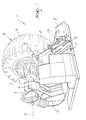
- the reference numeral 1 generally designates a machine for fitting and removing vehicle wheel tires.
- the machine 1 comprises a supporting frame 2 for means 3 for coupling and turning a rim C of a wheel R about a horizontal rotation axis A and for a working arm 4 provided with one end which supports a working head 5 for fitting and removing a tire P on and from the rim C.
- the means 3, in particular, are associated with the frame 2 by way of the interposition of movement means capable of allowing their movement on a plane which is substantially perpendicular to the rotation axis A.
- Such movement means are constituted for example by a rigid structure 6 for supporting the means 3, which is pivoted to the frame 2 and can rotate with respect to it about an axis that is parallel to the rotation axis A.
- the working head 5 comprises a bead breaker tool 5a and an extractor tool 5b, which are arranged on diametrically opposite sides with respect to the axis of the arm 4, the working head 5 being able to rotate about such axis in order to position in front of the wheel R the tool that is most suited for work.
- the arm 4 is kept substantially at right angles to the rotation axis A and is associated with the frame 2 by interposing first means 7 for translational actuation in a direction that is parallel to said axis.
- the arm 4 is associated with the first actuation means 7 by way of the interposition of second actuation means 8, which allow it to move between a first active end configuration, in which the working head 5 is arranged proximate to the first actuation means 7 and is spaced from the rotation axis A, and a second active end configuration, in which the working head 5 is spaced with respect to the first actuation means 7 and lies proximate to the rotation axis A.
- these second actuation means are suitable to change the inclination of the arm 4 with respect to the ground during its movement between the two end working configurations; in practice, the arm 4 can assume several intermediate working configurations, which are comprised between the end configurations and in each of which it has a different inclination and supports the working head 5 at a different distance from the second actuation means 8.
- first actuation means 7 comprise first straight guiding means, such as a pair of rails, which are rigidly connected to the frame 2, are parallel to the rotation axis A, are contained within a protective housing 9 and are not shown in the figures.
- a first slider 10 is engaged slidingly along the first straight guiding means and supports the second actuation means 8.
- the slider comprises a plate 11, below which two mutually facing C-shaped bodies 12 are arranged, each one of said bodies being engaged so that it can slide along one of the rails; two mutually parallel walls 15, perpendicular to the first guiding means, protrude above the plate 11.
- the first actuation means 7 comprise a first fluid-operated actuator of the linear type (jack) or of the rotary type (with a chain and/or gear drive), enclosed within the housing 9 and not shown.
- the second actuation means 8 comprise second guiding means, which are formed on the first slider 10 and along which a second slider 13 is engaged so that it can slide, said second slider supporting the end of the arm 4 that lies opposite the working head 5.
- Such second guiding means comprise two slots, each of which is constituted by a first portion 14a and a second portion 14b, both of which are straight and are provided through a corresponding wall 15 of the first slider 10.
- the portions 14a and 14b of one slot are identical and face, in a mirror-symmetrical manner, the portions 14a and 14b of the other slot and are engaged respectively by a first pin 16a and by second pin 16b, which lie transversely with respect to the arm 4 and are associated with the second slider 13, which in particular is arranged between the walls 15.
- the slots are such as to guide the second slider 13 in a combined motion (rotary and translational motion) between the two end working configurations.
- the arm 4 increases its inclination with respect to the ground, while the working head 5 traces a curved path in which the concavity is directed upward.
- the combined motion is obtained by way of the fact that the straight portions 14a and 14b of each slot are mutually inclined; however, alternative embodiments are not excluded in which the slots have different shapes and profiles, as in the case in which they are substantially curved.
- the movement of the second slider 13 with respect to the first slider 10 is obtained by means of a second fluid-operated actuator, the movement of the arm 4 being adjusted by the amount of fluid processed, or by means of a mechanically-actuated actuator of the worm screw type, the adjustment of the relative position between the sliders 10 and 13 being obtained by manual rotation of a crank connected to said screw; such actuators are not shown in detail in the figures.
- the arm 4 is associated with the second slider 13 by interposing third means 17 for rotary actuation about an axis that is substantially parallel to the rotation axis A.
- the arm 4 is in fact pivoted to the bottom of the second slider 13 and a third fluid-operated actuator 18 of the linear type is arranged above it, its ends being associated with a first hinge 19 and with a second hinge 20, which are pivoted respectively to the arm 4 and to the second slider 13.
- the actuation of the third actuator is designed to move the arm 4 away from/toward the wheel R when it is not active, allowing for example to arrange the working head 5 in front of both of the beads of the tire P without having to remove the rim C from the means 3.
- the operation of the present invention is as follows: initially, the user fits the rim C on the means 3, which he then arranges at a particularly modest height from the ground, which in practice is determined by the radial dimensions of the tire P.
- the user can arrange the working head 5 proximate to the circumferential portion of the rim C, regardless of its distance from the ground.
- the user can arrange the means 3 at a modest height and arrange the arm 4 proximate to the first end working configuration.
- the means 3 can be arranged higher, with the arm 4 proximate to the second end working configuration.
- the described invention achieves the proposed aim and object, and in particular the fact is stressed that it allows to simplify and increase the safety of operations for fitting and removing tires, the treads of which can be arranged at limited distances from the ground regardless of their dimensions.
Landscapes
- Engineering & Computer Science (AREA)
- Mechanical Engineering (AREA)
- Vehicle Cleaning, Maintenance, Repair, Refitting, And Outriggers (AREA)
- Handcart (AREA)
- Automobile Manufacture Line, Endless Track Vehicle, Trailer (AREA)
- Jib Cranes (AREA)
- Automatic Assembly (AREA)
Priority Applications (1)
| Application Number | Priority Date | Filing Date | Title |
|---|---|---|---|
| PL05107005T PL1623850T3 (pl) | 2004-08-03 | 2005-07-29 | Maszyna do zakładania i zdejmowania opon pojazdów |
Applications Claiming Priority (1)
| Application Number | Priority Date | Filing Date | Title |
|---|---|---|---|
| IT000205A ITMO20040205A1 (it) | 2004-08-03 | 2004-08-03 | 'macchina perfezionata per il motaggio e lo smontaggio di pneumatici di ruote per veicoli'. |
Publications (2)
| Publication Number | Publication Date |
|---|---|
| EP1623850A1 true EP1623850A1 (de) | 2006-02-08 |
| EP1623850B1 EP1623850B1 (de) | 2008-04-09 |
Family
ID=35169256
Family Applications (1)
| Application Number | Title | Priority Date | Filing Date |
|---|---|---|---|
| EP05107005A Expired - Lifetime EP1623850B1 (de) | 2004-08-03 | 2005-07-29 | Reifen-Montagemaschine |
Country Status (8)
| Country | Link |
|---|---|
| US (1) | US7188657B2 (de) |
| EP (1) | EP1623850B1 (de) |
| CN (1) | CN100478199C (de) |
| AT (1) | ATE391616T1 (de) |
| DE (1) | DE602005005904T2 (de) |
| ES (1) | ES2303665T3 (de) |
| IT (1) | ITMO20040205A1 (de) |
| PL (1) | PL1623850T3 (de) |
Cited By (7)
| Publication number | Priority date | Publication date | Assignee | Title |
|---|---|---|---|---|
| EP1977913A1 (de) * | 2007-04-05 | 2008-10-08 | Snap-on Equipment Srl a unico socio. | Reifenwechselgerät |
| WO2009138322A1 (en) * | 2008-05-15 | 2009-11-19 | Corghi S.P.A. | A tyre-removing method and a tyre-changing machine |
| ITVR20090097A1 (it) * | 2009-07-06 | 2011-01-07 | Mi Ro S R L Sa | Gruppo di lavoro particolarmente per il montaggio-smontaggio di un pneumatico su e da un cerchione. |
| ITMO20090209A1 (it) * | 2009-08-07 | 2011-02-08 | Giuliano Spa | Gruppo per la stallonatura di pneumatici in macchine smontagomme o simili |
| CN105799433A (zh) * | 2016-06-07 | 2016-07-27 | 营口通广汽车保修设备有限公司 | 一种大型轮胎扒胎机 |
| CN106080060A (zh) * | 2016-07-14 | 2016-11-09 | 哈尔滨工业大学 | 一种用于轮胎检测的扒胎机构 |
| IT201900007034A1 (it) | 2019-05-20 | 2020-11-20 | Devel S R L | Macchina smontagomme, in particolare per ruote di grandi dimensioni |
Families Citing this family (13)
| Publication number | Priority date | Publication date | Assignee | Title |
|---|---|---|---|---|
| ITMO20040044A1 (it) * | 2004-02-27 | 2004-05-27 | Sicam Srl | Macchina per il montaggio e lo smontaggio di pneumatici di ruote per veicoli |
| ITMO20060273A1 (it) * | 2006-09-08 | 2008-03-09 | Giuliano Spa | Macchina per il montaggio e lo smontaggio di pneumatici e cerchi di ruote per veicoli |
| ITVR20080050A1 (it) * | 2008-04-28 | 2009-10-29 | Butler Eng & Marketing | Gruppo stallonatore per una macchina monta-smontagomme |
| AU2009201429A1 (en) * | 2009-04-13 | 2010-10-28 | Ledger, Michael George Mr. | The Earthmover Tyre Chain Spindle |
| BR112013020403A2 (pt) * | 2011-02-11 | 2016-10-25 | Austin Engineering Ltd | aparelho de manipulação de artigo |
| CN102963224B (zh) * | 2012-11-27 | 2015-06-24 | 中意泰达(营口)汽车保修设备有限公司 | 轮胎折装机的自动拆装胎装置 |
| CN103182911B (zh) * | 2013-03-27 | 2015-01-28 | 常熟理工学院 | 扒胎机 |
| US11001108B2 (en) * | 2014-05-30 | 2021-05-11 | Snap-On Equipment Srl A Unico Socio | Mounting/demounting tool unit with preloaded tool |
| CN106004272A (zh) * | 2016-03-21 | 2016-10-12 | 昊龙科技(营口)发展有限公司 | 一种重型车辆轮胎拆装机的举升机构 |
| BR102016013188B1 (pt) * | 2016-06-08 | 2020-08-04 | Vale S/A | Dispositivo de instalação de blindagem em pneus de grande porte e método de instalação de blindagem |
| CN108944287B (zh) * | 2018-07-04 | 2020-10-09 | 重庆交通大学 | 轮胎扒胎装置 |
| CN109455045B (zh) * | 2018-10-23 | 2021-06-08 | 浙江跃岭股份有限公司 | 一种轮胎轮毂的拆卸工装 |
| CN110843431B (zh) * | 2019-12-03 | 2020-12-22 | 扬州瑞顺投资咨询有限公司 | 一种轮胎自动剥离外胎设备 |
Citations (3)
| Publication number | Priority date | Publication date | Assignee | Title |
|---|---|---|---|---|
| EP0042363A1 (de) * | 1980-06-12 | 1981-12-23 | Snap-on Equipment Srl a unico socio. | Maschine zum Demontieren und Montieren von Fahrzeugreifen |
| US4606393A (en) * | 1983-05-10 | 1986-08-19 | Corghi Electromeccanica S.P.A. | Tire removal machine with a simultaneously movable tool carrying head and automatic centering unit |
| EP1584496A2 (de) * | 2004-02-27 | 2005-10-12 | SICAM S.r.l. | Vorrichtung zum Montieren und Demontieren von Rädern |
Family Cites Families (3)
| Publication number | Priority date | Publication date | Assignee | Title |
|---|---|---|---|---|
| US5758703A (en) * | 1995-10-31 | 1998-06-02 | Onodani Machine Co., Ltd. | Apparatus for mounting and removing a tire from a wheel |
| IT1319475B1 (it) * | 2000-08-03 | 2003-10-10 | Corghi Spa | Dispositivo automatico per lo smontaggio ed il montaggio deipneumatici, e macchine smontagomme cosi' attrezzate |
| JP3626088B2 (ja) * | 2000-11-09 | 2005-03-02 | 小野谷機工株式会社 | 自動車タイヤ取外し方法、およびタイヤ取外し装置 |
-
2004
- 2004-08-03 IT IT000205A patent/ITMO20040205A1/it unknown
-
2005
- 2005-07-29 EP EP05107005A patent/EP1623850B1/de not_active Expired - Lifetime
- 2005-07-29 PL PL05107005T patent/PL1623850T3/pl unknown
- 2005-07-29 ES ES05107005T patent/ES2303665T3/es not_active Expired - Lifetime
- 2005-07-29 DE DE602005005904T patent/DE602005005904T2/de not_active Expired - Lifetime
- 2005-07-29 AT AT05107005T patent/ATE391616T1/de not_active IP Right Cessation
- 2005-07-29 US US11/192,177 patent/US7188657B2/en not_active Expired - Lifetime
- 2005-08-03 CN CNB2005100911388A patent/CN100478199C/zh not_active Expired - Fee Related
Patent Citations (3)
| Publication number | Priority date | Publication date | Assignee | Title |
|---|---|---|---|---|
| EP0042363A1 (de) * | 1980-06-12 | 1981-12-23 | Snap-on Equipment Srl a unico socio. | Maschine zum Demontieren und Montieren von Fahrzeugreifen |
| US4606393A (en) * | 1983-05-10 | 1986-08-19 | Corghi Electromeccanica S.P.A. | Tire removal machine with a simultaneously movable tool carrying head and automatic centering unit |
| EP1584496A2 (de) * | 2004-02-27 | 2005-10-12 | SICAM S.r.l. | Vorrichtung zum Montieren und Demontieren von Rädern |
Cited By (13)
| Publication number | Priority date | Publication date | Assignee | Title |
|---|---|---|---|---|
| EP1977913A1 (de) * | 2007-04-05 | 2008-10-08 | Snap-on Equipment Srl a unico socio. | Reifenwechselgerät |
| US7740043B2 (en) | 2007-04-05 | 2010-06-22 | Snap-On Equipment Srl A Unico Socio | Tire changer apparatus |
| WO2009138322A1 (en) * | 2008-05-15 | 2009-11-19 | Corghi S.P.A. | A tyre-removing method and a tyre-changing machine |
| ITVR20090097A1 (it) * | 2009-07-06 | 2011-01-07 | Mi Ro S R L Sa | Gruppo di lavoro particolarmente per il montaggio-smontaggio di un pneumatico su e da un cerchione. |
| CN101992662A (zh) * | 2009-08-07 | 2011-03-30 | 古丽亚诺股份公司 | 用于在轮胎更换机或类似物中对轮胎卷边的单元 |
| EP2281699A1 (de) * | 2009-08-07 | 2011-02-09 | Giuliano S.P.A. | Einheit zum Wulstabdrücken von Reifen in einer Reifenwechselmaschine |
| ITMO20090209A1 (it) * | 2009-08-07 | 2011-02-08 | Giuliano Spa | Gruppo per la stallonatura di pneumatici in macchine smontagomme o simili |
| US8424584B2 (en) | 2009-08-07 | 2013-04-23 | Giuliano Group S.P.A. | Unit for beading tires in tire changing machines or the like |
| CN101992662B (zh) * | 2009-08-07 | 2015-03-25 | 古丽亚诺集团股份公司 | 用于在轮胎更换机或类似物中对轮胎卷边的单元 |
| CN105799433A (zh) * | 2016-06-07 | 2016-07-27 | 营口通广汽车保修设备有限公司 | 一种大型轮胎扒胎机 |
| CN106080060A (zh) * | 2016-07-14 | 2016-11-09 | 哈尔滨工业大学 | 一种用于轮胎检测的扒胎机构 |
| IT201900007034A1 (it) | 2019-05-20 | 2020-11-20 | Devel S R L | Macchina smontagomme, in particolare per ruote di grandi dimensioni |
| EP3741591A1 (de) | 2019-05-20 | 2020-11-25 | Devel S.r.l. | Reifenwechselmaschine, speziell für grosse reifen |
Also Published As
| Publication number | Publication date |
|---|---|
| EP1623850B1 (de) | 2008-04-09 |
| CN100478199C (zh) | 2009-04-15 |
| PL1623850T3 (pl) | 2008-08-29 |
| ITMO20040205A1 (it) | 2004-11-03 |
| DE602005005904T2 (de) | 2009-06-04 |
| DE602005005904D1 (de) | 2008-05-21 |
| US20060027334A1 (en) | 2006-02-09 |
| ES2303665T3 (es) | 2008-08-16 |
| US7188657B2 (en) | 2007-03-13 |
| CN1733514A (zh) | 2006-02-15 |
| ATE391616T1 (de) | 2008-04-15 |
Similar Documents
| Publication | Publication Date | Title |
|---|---|---|
| EP1623850B1 (de) | Reifen-Montagemaschine | |
| EP1897709B1 (de) | Maschine zum Anbringen und Abnehmen von Fahrzeugreifen | |
| KR20230096939A (ko) | 타이어로부터 지느러미를 제거하는 방법 및 장치 | |
| EP1157860B1 (de) | Reifenabdrückvorrichtung für ein Raddemontiergerät, und Raddemontiergerät mit einer solchen Vorrichtung | |
| US4173245A (en) | Apparatus for mounting and dismounting vehicle tires | |
| US7341090B2 (en) | Assembling-disassembling machine provided with a overturnable mounting-dismounting tool | |
| KR20100010762A (ko) | 타이어 탈착기 | |
| EP1724563B1 (de) | Hebevorrichtung für die Montage von Fahrzeugräder auf einer Radauswuchtmaschine | |
| EP1524134A1 (de) | Reifenabdrückvorrichtung für ein Raddemontiergerät | |
| EP1584496B1 (de) | Vorrichtung zum Montieren und Demontieren von Rädern | |
| ES2924840T3 (es) | Aparato para cambiar neumáticos | |
| EP0624486B1 (de) | Reifenmontiergerät | |
| US9610812B2 (en) | Tire bead extraction device for tire-changing machines | |
| EP2281699B1 (de) | Einheit zum Wulstabdrücken von Reifen in einer Reifenwechselmaschine | |
| EP1479539A2 (de) | Maschine zum Auf- und Abmontieren von Reifen und Felgen von Kraftfahrzeugrädern | |
| CN212267164U (zh) | 一种可防止内胎损伤的大型卧式轮胎拆装机 | |
| CN115648863A (zh) | 摇摆式轮胎拆胎机及其工作方法 | |
| CN112588879A (zh) | 一种汽车轮毂制造成型加工系统 | |
| EP4532231B1 (de) | Reifenwechselvorrichtung | |
| EP1529666A2 (de) | Werkzeug für Reifenmontagemaschine | |
| WO2015044921A1 (en) | Tool-carrying arm for tyre-changing machines | |
| EP4480720A1 (de) | Vorrichtung zum entfernen und montieren von reifen von/auf felgen | |
| EP1717065B1 (de) | Werkzeug für die Montage/ Demontage von Fahrzeugreifen | |
| KR20260055739A (ko) | 타이어 재활용을 위한 휠 절단 분리장치 | |
| WO2022269499A1 (en) | Tyre changing machine, particularly for large wheels |
Legal Events
| Date | Code | Title | Description |
|---|---|---|---|
| PUAI | Public reference made under article 153(3) epc to a published international application that has entered the european phase |
Free format text: ORIGINAL CODE: 0009012 |
|
| AK | Designated contracting states |
Kind code of ref document: A1 Designated state(s): AT BE BG CH CY CZ DE DK EE ES FI FR GB GR HU IE IS IT LI LT LU LV MC NL PL PT RO SE SI SK TR |
|
| AX | Request for extension of the european patent |
Extension state: AL BA HR MK YU |
|
| 17P | Request for examination filed |
Effective date: 20060804 |
|
| 17Q | First examination report despatched |
Effective date: 20060831 |
|
| AKX | Designation fees paid |
Designated state(s): AT BE BG CH CY CZ DE DK EE ES FI FR GB GR HU IE IS IT LI LT LU LV MC NL PL PT RO SE SI SK TR |
|
| GRAP | Despatch of communication of intention to grant a patent |
Free format text: ORIGINAL CODE: EPIDOSNIGR1 |
|
| GRAS | Grant fee paid |
Free format text: ORIGINAL CODE: EPIDOSNIGR3 |
|
| GRAA | (expected) grant |
Free format text: ORIGINAL CODE: 0009210 |
|
| AK | Designated contracting states |
Kind code of ref document: B1 Designated state(s): AT BE BG CH CY CZ DE DK EE ES FI FR GB GR HU IE IS IT LI LT LU LV MC NL PL PT RO SE SI SK TR |
|
| REG | Reference to a national code |
Ref country code: GB Ref legal event code: FG4D |
|
| REG | Reference to a national code |
Ref country code: CH Ref legal event code: EP |
|
| REG | Reference to a national code |
Ref country code: IE Ref legal event code: FG4D |
|
| REF | Corresponds to: |
Ref document number: 602005005904 Country of ref document: DE Date of ref document: 20080521 Kind code of ref document: P |
|
| PGFP | Annual fee paid to national office [announced via postgrant information from national office to epo] |
Ref country code: ES Payment date: 20080603 Year of fee payment: 4 |
|
| REG | Reference to a national code |
Ref country code: ES Ref legal event code: FG2A Ref document number: 2303665 Country of ref document: ES Kind code of ref document: T3 |
|
| REG | Reference to a national code |
Ref country code: PL Ref legal event code: T3 |
|
| PG25 | Lapsed in a contracting state [announced via postgrant information from national office to epo] |
Ref country code: SI Free format text: LAPSE BECAUSE OF FAILURE TO SUBMIT A TRANSLATION OF THE DESCRIPTION OR TO PAY THE FEE WITHIN THE PRESCRIBED TIME-LIMIT Effective date: 20080409 |
|
| NLV1 | Nl: lapsed or annulled due to failure to fulfill the requirements of art. 29p and 29m of the patents act | ||
| PG25 | Lapsed in a contracting state [announced via postgrant information from national office to epo] |
Ref country code: PT Free format text: LAPSE BECAUSE OF FAILURE TO SUBMIT A TRANSLATION OF THE DESCRIPTION OR TO PAY THE FEE WITHIN THE PRESCRIBED TIME-LIMIT Effective date: 20080910 Ref country code: FI Free format text: LAPSE BECAUSE OF FAILURE TO SUBMIT A TRANSLATION OF THE DESCRIPTION OR TO PAY THE FEE WITHIN THE PRESCRIBED TIME-LIMIT Effective date: 20080409 Ref country code: BG Free format text: LAPSE BECAUSE OF FAILURE TO SUBMIT A TRANSLATION OF THE DESCRIPTION OR TO PAY THE FEE WITHIN THE PRESCRIBED TIME-LIMIT Effective date: 20080709 Ref country code: NL Free format text: LAPSE BECAUSE OF FAILURE TO SUBMIT A TRANSLATION OF THE DESCRIPTION OR TO PAY THE FEE WITHIN THE PRESCRIBED TIME-LIMIT Effective date: 20080409 |
|
| PG25 | Lapsed in a contracting state [announced via postgrant information from national office to epo] |
Ref country code: LV Free format text: LAPSE BECAUSE OF FAILURE TO SUBMIT A TRANSLATION OF THE DESCRIPTION OR TO PAY THE FEE WITHIN THE PRESCRIBED TIME-LIMIT Effective date: 20080409 Ref country code: AT Free format text: LAPSE BECAUSE OF FAILURE TO SUBMIT A TRANSLATION OF THE DESCRIPTION OR TO PAY THE FEE WITHIN THE PRESCRIBED TIME-LIMIT Effective date: 20080409 |
|
| PGFP | Annual fee paid to national office [announced via postgrant information from national office to epo] |
Ref country code: FR Payment date: 20080728 Year of fee payment: 4 Ref country code: PL Payment date: 20080729 Year of fee payment: 4 |
|
| ET | Fr: translation filed | ||
| PG25 | Lapsed in a contracting state [announced via postgrant information from national office to epo] |
Ref country code: IS Free format text: LAPSE BECAUSE OF FAILURE TO SUBMIT A TRANSLATION OF THE DESCRIPTION OR TO PAY THE FEE WITHIN THE PRESCRIBED TIME-LIMIT Effective date: 20080809 |
|
| PG25 | Lapsed in a contracting state [announced via postgrant information from national office to epo] |
Ref country code: LT Free format text: LAPSE BECAUSE OF FAILURE TO SUBMIT A TRANSLATION OF THE DESCRIPTION OR TO PAY THE FEE WITHIN THE PRESCRIBED TIME-LIMIT Effective date: 20080409 Ref country code: CZ Free format text: LAPSE BECAUSE OF FAILURE TO SUBMIT A TRANSLATION OF THE DESCRIPTION OR TO PAY THE FEE WITHIN THE PRESCRIBED TIME-LIMIT Effective date: 20080409 Ref country code: DK Free format text: LAPSE BECAUSE OF FAILURE TO SUBMIT A TRANSLATION OF THE DESCRIPTION OR TO PAY THE FEE WITHIN THE PRESCRIBED TIME-LIMIT Effective date: 20080409 Ref country code: SE Free format text: LAPSE BECAUSE OF FAILURE TO SUBMIT A TRANSLATION OF THE DESCRIPTION OR TO PAY THE FEE WITHIN THE PRESCRIBED TIME-LIMIT Effective date: 20080709 |
|
| PLBE | No opposition filed within time limit |
Free format text: ORIGINAL CODE: 0009261 |
|
| STAA | Information on the status of an ep patent application or granted ep patent |
Free format text: STATUS: NO OPPOSITION FILED WITHIN TIME LIMIT |
|
| PG25 | Lapsed in a contracting state [announced via postgrant information from national office to epo] |
Ref country code: RO Free format text: LAPSE BECAUSE OF FAILURE TO SUBMIT A TRANSLATION OF THE DESCRIPTION OR TO PAY THE FEE WITHIN THE PRESCRIBED TIME-LIMIT Effective date: 20080409 Ref country code: SK Free format text: LAPSE BECAUSE OF FAILURE TO SUBMIT A TRANSLATION OF THE DESCRIPTION OR TO PAY THE FEE WITHIN THE PRESCRIBED TIME-LIMIT Effective date: 20080409 |
|
| 26N | No opposition filed |
Effective date: 20090112 |
|
| PG25 | Lapsed in a contracting state [announced via postgrant information from national office to epo] |
Ref country code: MC Free format text: LAPSE BECAUSE OF NON-PAYMENT OF DUE FEES Effective date: 20080731 |
|
| PG25 | Lapsed in a contracting state [announced via postgrant information from national office to epo] |
Ref country code: EE Free format text: LAPSE BECAUSE OF FAILURE TO SUBMIT A TRANSLATION OF THE DESCRIPTION OR TO PAY THE FEE WITHIN THE PRESCRIBED TIME-LIMIT Effective date: 20080409 |
|
| PG25 | Lapsed in a contracting state [announced via postgrant information from national office to epo] |
Ref country code: IE Free format text: LAPSE BECAUSE OF NON-PAYMENT OF DUE FEES Effective date: 20080729 |
|
| PG25 | Lapsed in a contracting state [announced via postgrant information from national office to epo] |
Ref country code: CY Free format text: LAPSE BECAUSE OF FAILURE TO SUBMIT A TRANSLATION OF THE DESCRIPTION OR TO PAY THE FEE WITHIN THE PRESCRIBED TIME-LIMIT Effective date: 20080409 |
|
| REG | Reference to a national code |
Ref country code: CH Ref legal event code: PL |
|
| GBPC | Gb: european patent ceased through non-payment of renewal fee |
Effective date: 20090729 |
|
| REG | Reference to a national code |
Ref country code: FR Ref legal event code: ST Effective date: 20100331 |
|
| PG25 | Lapsed in a contracting state [announced via postgrant information from national office to epo] |
Ref country code: LI Free format text: LAPSE BECAUSE OF NON-PAYMENT OF DUE FEES Effective date: 20090731 Ref country code: FR Free format text: LAPSE BECAUSE OF NON-PAYMENT OF DUE FEES Effective date: 20090731 Ref country code: CH Free format text: LAPSE BECAUSE OF NON-PAYMENT OF DUE FEES Effective date: 20090731 |
|
| PG25 | Lapsed in a contracting state [announced via postgrant information from national office to epo] |
Ref country code: GB Free format text: LAPSE BECAUSE OF NON-PAYMENT OF DUE FEES Effective date: 20090729 |
|
| PG25 | Lapsed in a contracting state [announced via postgrant information from national office to epo] |
Ref country code: LU Free format text: LAPSE BECAUSE OF NON-PAYMENT OF DUE FEES Effective date: 20080729 Ref country code: HU Free format text: LAPSE BECAUSE OF FAILURE TO SUBMIT A TRANSLATION OF THE DESCRIPTION OR TO PAY THE FEE WITHIN THE PRESCRIBED TIME-LIMIT Effective date: 20081010 |
|
| REG | Reference to a national code |
Ref country code: ES Ref legal event code: FD2A Effective date: 20090730 |
|
| PG25 | Lapsed in a contracting state [announced via postgrant information from national office to epo] |
Ref country code: GR Free format text: LAPSE BECAUSE OF FAILURE TO SUBMIT A TRANSLATION OF THE DESCRIPTION OR TO PAY THE FEE WITHIN THE PRESCRIBED TIME-LIMIT Effective date: 20080710 Ref country code: ES Free format text: LAPSE BECAUSE OF NON-PAYMENT OF DUE FEES Effective date: 20090730 |
|
| PG25 | Lapsed in a contracting state [announced via postgrant information from national office to epo] |
Ref country code: PL Free format text: LAPSE BECAUSE OF NON-PAYMENT OF DUE FEES Effective date: 20090729 |
|
| REG | Reference to a national code |
Ref country code: PL Ref legal event code: LAPE |
|
| PGFP | Annual fee paid to national office [announced via postgrant information from national office to epo] |
Ref country code: TR Payment date: 20170728 Year of fee payment: 13 Ref country code: BE Payment date: 20170720 Year of fee payment: 13 |
|
| REG | Reference to a national code |
Ref country code: DE Ref legal event code: R082 Ref document number: 602005005904 Country of ref document: DE Representative=s name: SCHMITT-NILSON SCHRAUD WAIBEL WOHLFROM PATENTA, DE |
|
| REG | Reference to a national code |
Ref country code: BE Ref legal event code: MM Effective date: 20180731 |
|
| PG25 | Lapsed in a contracting state [announced via postgrant information from national office to epo] |
Ref country code: BE Free format text: LAPSE BECAUSE OF NON-PAYMENT OF DUE FEES Effective date: 20180731 |
|
| PGFP | Annual fee paid to national office [announced via postgrant information from national office to epo] |
Ref country code: DE Payment date: 20200925 Year of fee payment: 16 |
|
| PGFP | Annual fee paid to national office [announced via postgrant information from national office to epo] |
Ref country code: IT Payment date: 20200731 Year of fee payment: 16 |
|
| REG | Reference to a national code |
Ref country code: DE Ref legal event code: R119 Ref document number: 602005005904 Country of ref document: DE |
|
| PG25 | Lapsed in a contracting state [announced via postgrant information from national office to epo] |
Ref country code: DE Free format text: LAPSE BECAUSE OF NON-PAYMENT OF DUE FEES Effective date: 20220201 |
|
| PG25 | Lapsed in a contracting state [announced via postgrant information from national office to epo] |
Ref country code: TR Free format text: LAPSE BECAUSE OF NON-PAYMENT OF DUE FEES Effective date: 20180729 |
|
| PG25 | Lapsed in a contracting state [announced via postgrant information from national office to epo] |
Ref country code: IT Free format text: LAPSE BECAUSE OF NON-PAYMENT OF DUE FEES Effective date: 20210729 |