EP1623896A1 - Verfahren und vorrichtung zur scheibenwischersteuerung - Google Patents
Verfahren und vorrichtung zur scheibenwischersteuerung Download PDFInfo
- Publication number
- EP1623896A1 EP1623896A1 EP04732785A EP04732785A EP1623896A1 EP 1623896 A1 EP1623896 A1 EP 1623896A1 EP 04732785 A EP04732785 A EP 04732785A EP 04732785 A EP04732785 A EP 04732785A EP 1623896 A1 EP1623896 A1 EP 1623896A1
- Authority
- EP
- European Patent Office
- Prior art keywords
- wiper
- wiping
- rainfall
- level
- raindrops
- Prior art date
- Legal status (The legal status is an assumption and is not a legal conclusion. Google has not performed a legal analysis and makes no representation as to the accuracy of the status listed.)
- Withdrawn
Links
Images


Classifications
-
- B—PERFORMING OPERATIONS; TRANSPORTING
- B60—VEHICLES IN GENERAL
- B60S—SERVICING, CLEANING, REPAIRING, SUPPORTING, LIFTING, OR MANOEUVRING OF VEHICLES, NOT OTHERWISE PROVIDED FOR
- B60S1/00—Cleaning of vehicles
- B60S1/02—Cleaning windscreens, windows or optical devices
- B60S1/04—Wipers or the like, e.g. scrapers
- B60S1/06—Wipers or the like, e.g. scrapers characterised by the drive
- B60S1/08—Wipers or the like, e.g. scrapers characterised by the drive electrically driven
- B60S1/0818—Wipers or the like, e.g. scrapers characterised by the drive electrically driven including control systems responsive to external conditions, e.g. by detection of moisture, dirt or the like
-
- G—PHYSICS
- G01—MEASURING; TESTING
- G01N—INVESTIGATING OR ANALYSING MATERIALS BY DETERMINING THEIR CHEMICAL OR PHYSICAL PROPERTIES
- G01N21/00—Investigating or analysing materials by the use of optical means, i.e. using sub-millimetre waves, infrared, visible or ultraviolet light
- G01N21/17—Systems in which incident light is modified in accordance with the properties of the material investigated
-
- G—PHYSICS
- G01—MEASURING; TESTING
- G01W—METEOROLOGY
- G01W1/00—Meteorology
- G01W1/14—Rainfall or precipitation gauges
Definitions
- the present invention relates to a wiper control method and a wiper control device which can smoothly respond to change of rainfall situation and more particularly to a wiper control method and a wiper control device which can smoothly respond to rapid change of rainfall situation when passing through a rainfall shutoff environment such as in a tunnel.
- the present invention relates to a wiper control method and a wiper control device which can appropriately follow change of the rainfall situation and more particularly to a wiper control method and a wiper control device which can appropriately follow the change of rainfall situation if an adhesion amount of rainfall onto a windshield is rapidly changed such as entrance to/exit from a tunnel.
- a conventional device for controlling a wiper by injecting an LED light or the like onto a detection surface provided on a windshield and by receiving a reflected light by a light receiving element and by performing control based on an output signal of the light receiving element.
- a sensitivity adjustment volume is provided as the JP-A-4-349053.
- the adjustment by this sensitivity adjustment volume has, as shown in Fig. 1, three types of intermittence time which can be chosen for one rainfall state, and either of short, medium or long is chosen based on the position of the sensitivity adjustment volume set manually by the driver.
- a method for detecting dynamic adhesion of raindrops JP-A-2001-180447
- a method for evaluating fluctuation of an output signal of a light receiving element JP-A-2002-277386
- JP-A-2002-277386 a method for evaluating fluctuation of an output signal of a light receiving element
- a method for detecting raindrops a method for detecting the raindrop in comparison with a reference value (so-called threshold value method) (JP-A-61-37560, for example) and a method for detecting raindrops by an integrated value of the light receiving element output (so-called integration method) (JP-A-4-349053, for example) are disclosed.
- a vehicle when running, it may pass through an environment where rainfall is shut off as in a tunnel.
- the rainfall situation changes before entrance to the tunnel, during driving in the tunnel and after exit from the tunnel.
- the rainfall situation is rapidly changed at entrance to the tunnel and exit therefrom.
- a conventional device for controlling a wiper by injecting an LED light or the like onto a detection surface provided on a windshield and performing control based on the light amount of its reflected light In this device, the area of the above detection surface is extremely smaller than the total area of the windshield. Therefore, in order to improve the accuracy, a method for determining intermittence of a wiper based on a water amount carried by the wiper through wiping is proposed (International Publication No. WO 91/03393).
- the present invention provides a wiper control method and a wiper control device which can smoothly respond to change of rainfall situation and more particularly a wiper control method and a wiper control device which can smoothly respond to rapid change of rainfall situation when passing through a rainfall shutoff environment such as in a tunnel.
- the diameter and supply amount of water drops by splashing are not large, and it takes a certain time for the visibility to be deteriorated by splashing.
- the detection area of the rain sensor is extremely smaller than the whole surface of the windshield in general, and the state of the entire windshield is estimated based on the raindrops adhering onto the small detection surface. Therefore, if adhesion of water drops by splashing is wiped with a high wiping frequency, unnecessary wiping frequents before deterioration of the visibility on the windshield, which is bothersome. Therefore, in the tunnel, it is necessary to keep the wiping frequency low to some extent while responding to adhesion of splashing.
- the rainfall situation is almost the same as before entrance, and the same level of detection sensitivity and the same level of wiping frequency as before entrance to the tunnel are considered to be necessary.
- a desire to ensure safety becomes dominant at rapid change of environment, especially when the environment is rapidly deteriorated.
- the driver's sense gets used to a favorable visibility without rainfall, and change of the environment at exit from the tunnel tends to be felt as more rapid.
- the driver wants to wipe the rapid deterioration of the visibility quickly in many cases. From this, even if the rainfall is the same before and after the tunnel, higher detection sensitivity and wiping with higher frequency are desired at the exit from the tunnel. Even at the exit from the tunnel, if the rainfall is small, it takes time for the visibility to deteriorate, and such higher detection sensitivity and wiping frequency are not required.
- the inventors obtained the finding that in the tunnel, it is necessary to keep the wiping frequency against splashed water low while preparing for the exit from the tunnel. That is, the wiping frequency is preferably kept low while responding to fine water drops such as splash, the wiping intermittence time is made longer and raindrops with larger diameter should be responded quickly while the wiping frequency is increased.
- Fig. 2 is a graph showing a waveform model of an output signal of a light receiving element in running at a high speed.
- the inventors obtained the finding that in running at a high speed, the detection accuracy can be improved by detecting adhesion of raindrops with signal change in the mask section as an object to be detected. Especially, it is preferable to detect the signal change immediately after the passage of wiper blade over the detection surface.
- adhesion of the raindrops is detected based on the momentum of the output signal of the light receiving element in the mask section. In this way, it is not necessary any more to grasp and exclude the signal change caused by passage of the wiper blade, and control can be more simplified.
- the wiper waiting time (including intermittent/continuous operation) is determined by raindrop adhesion cycle by difference and fluctuation of a signal at adhesion.
- the water amount collected by the wiper is not referred to at all.
- the water amount collected by the wiper is used as a condition to determine a point of change in rainfall by the water amount collected by the wiper till the adhesion cycle which cannot maintain the intermittent state (including continuous wiping) is detected and to cause transition to stop to happen.
- Fig. 19 shows control of the wiping state by the wiper (including stop, intermittent wiping and continuous wiping) based on adhesion of raindrops.
- wiping is performed in a predetermined wiping state (1-second intermittent time, for example) according to the adhesion cycle of the raindrops.
- the wiping frequency is changed in the direction approaching the stop so as to match it to the current situation. In the above example, for example, the frequency is lowered to 2-second intermittence time.
- passing water amount a large value is continuously detected at every wiping due to influence of the dripping water or the like.
- control of an auto wiper is generally executed so that the wiping frequency is increased stepwise at start of raining except an exceptional case of rainstorm. This stepwise control is necessary to match the operation of the wiper to the human senses.
- the wiping frequency should be increased stepwise from stop if it is raining at exit from the tunnel (stop -> 3-second intermittent -> 2-second intermittent -> 1-second intermittent, for example). Then, it takes time for the wiping frequency to adapt to the rainfall. Such control does not match the driver's desire.
- intermittence inside the sensor (WP waiting time) is determined by the adhesion cycle and is not brought to the stop state. That is, stop of wiping by the wiper does not mean stop of intermittence but wiping is resumed at timing when the next adhesion cycle is established, and if there is no adhesion, it is linked to the stop state in the end.
- control of intermittence is executed independently based on adhesion of raindrops with the intermittence before entrance into the tunnel, a wiping signal outputted according to the intermittence is masked so that wiping by the wiper is apparently stopped, and at exit from the tunnel, following to the rainfall is started from the intermittent state determined independently.
- Fig. 1 is a table for explaining a conventional wiper control method.
- the first preferred embodiment of the present invention is to determine such a driving scene that a vehicle enters a rainfall shutoff environment such as a tunnel from a certain rainfall situation and to adjust correspondence between the predetermined rainfall level and a predetermined wiping state.
- Fig. 3 is a conceptual diagram for explaining change of the rainfall level at passage of a tunnel.
- a running vehicle enters a tunnel at P and exits from the tunnel at R.
- a certain rainfall level continues before entrance to the tunnel, and the rainfall level is decreased close to zero (no rainfall) by entrance into the tunnel. That is, at the entrance into the tunnel, the rainfall level is lowered by a predetermined amount L within a predetermined time t. Then, the state that the rainfall level is lowered is maintained for a certain period of time and the rainfall level is returned to original by exit from the tunnel.
- the driving scene that the vehicle enters the rainfall shutoff environment such as a tunnel from a certain rainfall situation can be determined.
- Such determination of the driving scene can be made, for example, by identifying a status (vehicle state and driving environment state) at a certain point of time and by detecting that a specific event occurs at a point of time later than the point.
- the driving environment state is a certain rainfall situation
- the driving environment state is a certain rainfall situation
- a control method by a conventional sensitivity adjustment volume will be explained with reference to Fig. 1.
- the conventional control method by sensitivity adjustment volume if the rainfall state is specific drizzling rain, for example, the step of intermittence time is set to 7. The relationship between this specific drizzling rain and the step 7 is fixed from this time. That is, if the rainfall state is determined as drizzling, the intermittence time of the step 7 is selected all the time. According to the sensitivity volume setting by the driver, actual intermittence time is chosen from the three modes of intermittence time included in the step 7.
- the relation between the rainfall state level and the intermittence time step is not fixed to one-to-one but it is changed dynamically. That is, the correspondence between each of the rainfall state levels and each of the wiping states is changed according to the driving scene.
- Fig. 4 is a conceptual diagram for explaining the first preferred embodiment of the present invention.
- Fig. 4 includes Table 1 and Table 2.
- Table 1 rainfall levels are defined stepwise.
- Table 2 the wiping state is classified and defined as a plurality of stepwise wiping levels according to the wiping waiting time and wiping speed.
- the wiping waiting time includes zero (which means no waiting time).
- Fig. 4 shows a definition example of the wiping state.
- the wiping state as shown in Fig. 4, for example, the longer the wiping waiting time is, the longer the intermittence time becomes, and if the wiping waiting time becomes infinite ( ⁇ ), it causes the stop state.
- the shorter the wiping waiting time is, the shorter the intermittence time becomes, and when the wiping waiting time is zero, it means continuous wiping.
- the continuous wiping is divided by wiping speed into high-speed continuous wiping and low-speed continuous wiping. By combining the wiping waiting time and the wiping speed in this way, various wiping operations of the wiper can be controlled.
- the first preferred embodiment of the present invention dynamically associates each item of the rainfall level in Table 1 to each item of the wiping level in Table 2. For example, in a tunnel, the rainfall level requiring continuous wiping after exit from the tunnel is associated with a higher wiping level to raise the wiping level, while the rainfall level such as adhesion of micro splashed water is associated with a lower wiping level to lower the wiping level.
- the rainfall levels n to n-3 on the larger rainfall side are allocated to high-speed continuous wiping, the rainfall levels n-4 to n-8 to low-speed continuous wiping and the rainfall levels n-9 to n-15 to intermittence 1.
- the rainfall levels n to n-8 may be allocated to the high-speed continuous wiping and the rainfall levels n-9 to n-15 to intermittence 4 with longer wiping waiting time.
- to raise the wiping level means to raise the wiping level associated with a specific rainfall level to a higher one (shorter waiting time or faster wiping speed).
- to decrease or lower the wiping level means to bring the wiping level associated with a specific rainfall level to a lower one (longer waiting time or slower wiping speed).
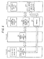
- Fig. 5 is a block diagram for explaining the construction of the wiper control device according to the first preferred embodiment of the present invention in layered structure.
- the wiper control device according to the first preferred embodiment of the present invention can be represented by four-layered construction, and between each of the layers, data or signals are made to communicate through a common interface such as SAP (service access point), for example.
- SAP service access point
- a first layer includes a rain sensor physical layer 90 and a vehicle control computer or a wiper motor 100
- a second layer includes a raindrop information detection part 22, a vehicle information detection part 24 and an interface 26
- a third layer includes a rainfall level generation part 32
- a fourth layer includes a wiping state control part 42 and a wiper driving signal generation part 48.
- the rain sensor physical layer 90 is comprised by an optical mechanism and a circuit, an optical mechanism in the method that light from a light emitting element is reflected by a detection surface and a reflected light is received by a light receiving element and circuits such as a filter circuit for processing output of the light receiving element, an amplifier circuit, an A/D converter, etc., for example.
- An example of such a rain sensor is disclosed in the JP-A-2001-180447 and the JP-A-2002-277386.
- the optical mechanism will be described.
- Light emitted from a light emitting element such as an LED, for example, is led to a glass substrate (windshield glass) which is a transparent substrate to detect water drops through a prism glass or the like.
- the led light is fully reflected by the detection surface and enters a light receiving element such as a photodiode, for example, through the above prism glass.
- a light receiving element such as a photodiode, for example, through the above prism glass.
- Such an optical mechanism is arranged/constituted so that in the state where no water drop adheres, for example, the maximum output is generated at the light receiving element. At this time, if there is adhesion of a water drop or the like on the detection surface, the output of the light receiving element is lowered.
- a detection surface is arranged in the range of wiping operation of the wiper.
- a vehicle control computer or wiper motor 100 is connected to the wiper control device of the present invention and can be selected as appropriate according to the preferred embodiment of the present invention.
- the wiper motor is controlled through the vehicle control computer.
- the wiper motor is directly controlled.
- a raindrop information detection part 22 detects and outputs various types of information relating to raindrops based on an output signal of the light receiving element of the rain sensor.
- Information includes phenomenon as adhesion of raindrops, fluctuation of adhering rain drops, displacement amount of signal level per predetermined time, etc.
- a vehicle information detection part 24 detects and outputs various type of information controlled on the vehicle side.
- Vehicle information includes an auto stop signal indicating operation section of the wiper, car speed information, position information of wiper switch, auto light information, set position information of sensitivity volume, position information of light switch, etc.
- An interface 26 converts a wiper driving signal from the higher layer (fourth layer) to a signal in the format suitable for the vehicle control computer or wiper motor, respectively and outputs it.
- a rainfall level generation part 32 determines the current rainfall level based on the output of the raindrop information detection part 22 and generates the rainfall level. In concrete, to which of the rainfall levels defined in Table 1 of Fig. 2 the level corresponds is determined. As mentioned later, it is preferable that an established reference rainfall level and a temporary rainfall level should be provided for the rainfall level.
- a wiping state control part 42 determines a driving scene using the car speed information, rainfall level information, auto light information, control information such as a timer, etc. and adjust the correspondence between the rainfall level and the wiping level according to the determined driving scene. For example, the wiping state control part 42 determines the driving scene based on the rainfall level generated by the rainfall level generation part 32, car speed information detected by the vehicle information detection part 24, auto light information, etc. and determines to which wiping level a predetermined rainfall level is allocated according to the determined driving scene. Also, when the sensitivity volume has been set, the sensitivity volume is considered if necessary to adjust the correspondence between the rainfall level and the wiping level.
- the wiping state control part 42 is provided with a function to determine a driving scene and a function to adjust correspondence in this way.
- the wiping state control part 42 determines the driving scene that the vehicle enters the tunnel from the certain rainfall situation using control information such as car speed information, rainfall level information, auto light information, timer, etc. and allocates the rainfall level at a predetermined threshold value or more to the wiping level higher than that before entrance to the tunnel and the rainfall level less than the predetermined threshold value to the wiping level equal to or lower than that before entrance to the tunnel.
- a wiper driving signal generation part 48 determines a wiping state as the items in Table 2 of Fig. 4 based on the correspondence between the rainfall level and the wiping level set by the wiping state control part 42 and the rainfall level generated by the rainfall level generation part 32 and outputs a wiper driving signal of a predetermined wiping waiting time and a predetermined wiping speed.
- the wiper driving signal is outputted to the vehicle control computer or wiper motor 100 through the interface 26.
- the rainfall level can be determined based on the raindrop information detected by the raindrop information detection part 22.
- a method for detecting the raindrop information used for generation of the rainfall level will be described.
- the method for detecting the rainfall information the method for detecting dynamic adhesion of raindrops disclosed by the inventors (JP-A-2001-180447) can be used. With this method, a delay signal is generated from a signal of the light receiving element, a difference between the signal of the light receiving element and the delay signal is acquired and it is determined that there was a collision of a water drop on the detection surface when the difference occurs.
- a first delay signal of the signal of the light receiving element is generated, a second delay signal is generated from the first delay signal, a difference between the first delay signal and the second delay signal is acquired and when the difference occurs, it is determined that there was a collision of a water drop on the detection surface.
- the raindrop information detection part 22 detects the phenomenon of collision of the raindrops on the detection surface and outputs it as adhesion of raindrops.
- the rainfall level generation part 32 may determine the level of rainfall based on such raindrop adhesion information and generate the current rainfall level. For example, it may be so constituted that rainfall levels are defined stepwise based on the number of adhesion per predetermined time, and the rainfall level generation part 32 determines the rainfall level according to the number of adhesion per predetermined time. In concrete, the larger the number of adhesion per predetermined time is, the higher the rainfall level becomes, and if the number of adhesion is small, the rainfall level may be lowered. In this way, the rainfall state can be divided into detailed levels and defined based on the raindrop adhesion information.
- fluctuation of adhering raindrops can be used.
- a method is disclosed which can indirectly detect dynamic fluctuation of adhesion by dynamic fluctuation of a signal of a light receiving element obtained through the raindrops adhering on the detection surface and determines the size of a raindrop and how the raindrops are hitting by a change pattern of the fluctuation of the signal.
- the size and the like of the raindrops can be estimated by information of raindrop fluctuation, by combining this raindrop fluctuation information with adhesion of raindrops, the rainfall state can be divided into further detailed levels.
- the change pattern of the fluctuation of the signal used for the above determination can be a change pattern of time of fluctuation of the above signal, and the length of fluctuation of adhesion can be detected indirectly by the length of fluctuation of the signal. For example, if the adhesion is a raindrop, the larger the raindrop is, the longer the fluctuation lasts as its characteristic, and the size of the raindrop can be estimated from the length of the detected fluctuation.
- the change pattern of the fluctuation of the signal used for the above determination can be a change pattern of the size of fluctuation of the above signal, and the size of fluctuation of adhesion can be indirectly detected by the size of the fluctuation of the signal.
- the adhesion is a raindrop
- Parameters for representing the size of fluctuation include the number of change times of increase/decrease within the fluctuation, change amount of the increase, direction of increase/decrease of the change, etc.
- the raindrop information detection part 22 detects and outputs the change pattern of the signal fluctuation.
- the length of the signal fluctuation, the number of change times of increase/decrease within the signal fluctuation, the change amount of increase, direction of increase/decrease of the change, etc. are outputted.
- the rainfall level generation part 32 may determine the state of rainfall in more detail from the adhesion of raindrops and change pattern of the signal fluctuation detected by the raindrop information detection part 22 in this way.
- the rainfall level generation part 32 may determine the size of the raindrops from the change pattern of the detected signal fluctuation based on this table.
- the rainfall level generation part 32 may determine the rainfall level from the number of adhering raindrops detected per predetermined time and the size of adhering raindrops and generate the current rainfall level.
- a method for detecting raindrop information a method for detecting raindrops by comparison with a reference value (so-called threshold value method) disclosed in the JP-A-61-37560 and a method for detecting raindrops from an integrated value of light receiving element output (so-called integration method) disclosed in the JP-A-4-349053 can be used.
- the rainfall level generation part 32 can determine the rainfall level based on the raindrop information detected by these methods.
- the rainfall level generation part 32 generates an established reference rainfall level and a temporary rainfall level.
- the temporary rainfall level is determined in rapid response to change of the rainfall situation. That is, if detection information from the raindrop information detection part 22 is changed, the temporary rainfall level is changed in accordance with it.
- the established reference rainfall level is determined following a relatively long determination period.
- the rainfall level generation part 32 determines the temporary rainfall level in accordance with it. It is determined using a timer if the temporary rainfall level is maintained for a predetermined period of time. If the temporary rainfall level is maintained for a predetermined period of time, the reference rainfall level is updated by the maintained temporary rainfall level. In the meantime, if the temporary rainfall level is not maintained for a predetermined period of time but for the time being, the reference rainfall level is not changed but maintained as original.
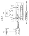
- Fig. 6 is a block diagram for explaining the configuration of the wiping state control part
- Figs. 7 and 8 are conceptual diagrams for explaining a method for scene determination
- Fig. 9, 10 are conceptual diagrams for explaining a method of dynamic link.
- the wiping state control part 42 has a scene dissolution part 44 and a link part 46.
- the scene dissolution part 44 determines such a driving scene that a vehicle enters a tunnel from a predetermined rainfall situation from the rainfall level generated by the rainfall level generation part 32, car speed information detected by the vehicle information detection part 24 and auto light information and adjusts the correspondence between a predetermined rainfall level and a predetermined wiping level.
- a link pattern for linking Table 1 (rainfall level) with Table 2 (wiping state) as shown in Fig. 4 is determined, and ID is outputted as identification information for identifying the determined link pattern.
- the link part 46 selects a specific link pattern based on the identification information outputted by the scene dissolution part 44 from a plurality of link patterns and links the rainfall level items and the wiping level items with the selected link pattern.
- the link pattern to be selected associates the rainfall level at a predetermined threshold value or more to a higher wiping level and the rainfall level less than the predetermined threshold value to a lower wiping level.
- the scene dissolution part 44 includes a status control part 441, an entity scheduler 442, a pattern table control part 444 and a pattern scheduler 446.
- the status control part 441 controls status comprised by a current vehicle state and a current driving environment state.
- the current vehicle state stop, driving, acceleration, deceleration, etc.
- the current driving environment state is determined from the rainfall level, auto light information, etc.
- the driving environment state is, for example, a rainfall state (fair weather state, rainy state), a light/dark state, inside a tunnel, etc. This rainfall state is determined from the rainfall level.
- the light/dark state is determined from the auto light information, position information of light switch, etc., for example.
- the status control part 441 selects a current status from a status information table as shown in Fig. 8 with the determined current vehicle state and the current driving environment state as a reference.
- Table of Fig. 8 different statuses are set to the respective addresses, and each of the addresses is linked to the entity information and the pattern table information. Therefore, the status control part 441 selects one address according to the combination of the vehicle state and the driving environment. When the status is changed, the address of the changed status is selected.
- the entity scheduler 442 starts only an entity 443 liked to the status determined by the status control part 441 from the plurality of entities. As shown in Fig. 8, specific entity information is linked to each of the status addresses, and only the entity 443 linked to the current status is identified and started. In concrete, by the entity ID included in the entity information, one or plural specified entities are identified and started.
- the pattern table control part 444 selects and sets a pattern table 445 linked to the status determined by the status control part 441 from a plurality of pattern tables. As shown in Fig. 8, specific pattern table information is linked to each of the status addresses, and only the pattern table 445 linked to the current status is identified and set as an object to be monitored. In concrete, by the pattern table ID included in the pattern table information, one or plural specified pattern tables are identified and selected.
- entities are provided in plural in accordance with the number of events to be detected. Also, it is preferable that each of the entities monitors a specific event. For example, an acceleration detection entity detects an event of vehicle acceleration. Also, a fair weather state detection entity detects an event that rain has stopped and it is cleared up. A tunnel entrance detection entity detects an event of entrance of a vehicle to a tunnel. And according to the status, only a specific entity among the plurality of entities is started by the entity scheduler 442. Each of the entities included in the started entity 443 has a function to detect occurrence of a predetermined event and to register the detected event in a set pattern table 445.
- Such detection of events can be made from temporary rainfall level information, car speed information, auto light information, etc.
- the entity has a timer and can detect an event established including a concept of time such as an event that a specific state (stop of rainfall, for example) lasts for a predetermined period of time or an event that the rainfall level or the like is changed by a predetermined amount in a predetermined period of time.
- Each of the pattern tables corresponds to a specific link pattern, respectively, and provided in the same number as that of the link patterns.
- Each of the pattern tables has a pattern of event registration block corresponding to a driving scene to be determined, and when all the event registration blocks are filled in a specific pattern table, the specific driving scene is detected.
- Such pattern tables are preferably provided in plural according to the driving scenes to be detected. From the plurality of pattern tables, a predetermined pattern table is selected by the pattern table control part 444 and set as an object to be monitored.
- the pattern table 445 set by the pattern table control part 444 has one or plural event registration blocks for registering events. Then, various specific patterns are set by masking arbitrary blocks. Or specific patterns may be set by adding identification information such as ID to identify specific events to each of the event registration blocks so that only the specific events are registered.
- the pattern scheduler 446 monitors the set pattern table, detects the pattern table in which events are registered in all the event registration blocks and outputs the ID given to the detected pattern table. This ID is information for identifying the link table.
- the pattern scheduler 446 may be combined with the above-mentioned pattern table control part 444 so that one pattern scheduler has both functions.
- the link part 446 selects a specific link pattern based on the ID outputted by the pattern scheduler 446, as shown in Fig. 9, and links the rainfall level items to the wiping state items by the selected link pattern.
- different correspondence patterns are set for each of the link patterns, and by selecting an appropriate link pattern according to the driving scene, correspondence can be adjusted appropriately.
- the rainfall level at a predetermined threshold value th or more may be allocated to continuous wiping and the rainfall level less than the predetermined threshold value th to a longer intermittence time of intermittence time 3 or less.
- the rainfall level not smaller than a first threshold level th1 is allocated to continuous wiping and the rainfall level less than a second threshold level th2 to a long intermittence time of intermittence time 3 or less.
- the wiping frequency is increased quickly for rainfall more than a predetermined amount in preparation for exit.
- the entity scheduler 442 is provided and only the necessary entity is started for the current status.
- the event registration block of the pattern table accepts only specific events, all the entities may be operated at the same time. Therefore, the entity scheduler 442 may be omitted in the configuration.
- the same control can be realized by limiting the number of entities operating at the same time. This is because the event to be monitored will change according to the status and it is not necessary to operate all the entities at the same time.
- the status is a driving state, for example, the event of stop should be detected, but the entity to detect the event of start from stop is not required.
- the status is the fair weather state, the event to be detected is start of rain, adhesion of mist, continuation of fair weather, etc., and the entity to detect the event of stop of rainfall does not need to be operated.
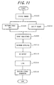
- Fig. 11 is a flowchart for explaining the operation of the first preferred embodiment.
- the status control part 441 determines the current status and selects the applicable address of the status information table. For example, when the rainfall level is changed, it is preferable to determine this by the reference rainfall level. That is because rainfall in the nature will change, and if a status is changed following a temporary change, behavior of the wiper will become unstable. Therefore, the status is changed at the stage that the reference rainfall level is changed from fair weather to a specific rainfall level, for example.
- a rainfall level not smaller than a predetermined threshold value is selected. Also, if car speed information is provided, a status with a constant driving speed is selected.
- the entity scheduler 442 receives the entity information linked to the address of the status information table selected by the status control part 441 and identifies and starts the specified entity.
- the entity started here is an entity to detect an event that the rainfall level is lowered by a predetermined amount in a predetermined time and this lowered state lasts for a predetermined period of time. Also, if auto light information is provided, an entity is started to detect an event that the auto light system determines turning-on of head lights (including front position lights) upon entrance to the tunnel.
- the pattern table control part 444 receives the pattern table information linked to the address of the status information table selected by the status control part 441 and selects the specified pattern table and sets it as an object to be monitored.
- the pattern table selected here is a pattern table having an event registration block for registering an event to be detected by the entity started at Step 204.
- the entity having been started detects its own event and registers the detected event in the pattern table.
- the event registration blocks to which the event is allocated are used.
- detection of events and registration of detected events are performed at each entity when there are a plurality of entities.
- an event that the rainfall level is lowered by a predetermined amount in a predetermined time and this lowered state lasts for a predetermined period of time is detected and registered.
- the pattern scheduler 446 detects the pattern table in which events have been registered in all the event registration blocks.
- the ID allocated to the detected pattern table is outputted.
- a pattern table is detected with such an event registered that the rainfall level is lowered by a predetermined level in a predetermined time and this lowered state lasts for a predetermined period of time, and a driving scene that a vehicle enters a tunnel from a predetermined rainfall state is determined.
- the link part 46 selects a specified link pattern from a plurality of link patterns based on the ID outputted by the pattern scheduler 446 and links the rainfall level table to the wiping state table by the selected link pattern.
- the rainfall level not smaller than the predetermined threshold level th is allocated to continuous wiping and the rainfall level less than the predetermined threshold value th to a long intermittence time of intermittence 3 or less.
- the wiper driving signal generation part 48 applies the temporary rainfall level generated by the rainfall level generation part 32 to a rainfall level table as shown in Fig. 9, determines the wiping state of the wiper by selecting a specific wiping level associated with the rainfall level and outputs a wiper driving signal of a predetermined wiping waiting time and a predetermined wiping speed.
- a low wiping level long intermittence time
- a high wiping level continuous wiping
- the rainfall not smaller than the threshold value th is selected as the rainfall not smaller than the threshold value th.
- such a driving scene that a vehicle enters a tunnel from a predetermined rainfall situation by occurrence of a specific event is determined, and a link pattern corresponding to this driving scene can be selected. Also, using this link pattern, the wiping level is set low for the low level of rainfall less than the predetermined rainfall level and the wiping level is set high for the high level of rainfall at the predetermined rainfall level or more so that change of rainfall situation at passage through a tunnel can be followed.
- processing to return the pattern table to that before entrance to the tunnel may be executed by detecting the event that a predetermined time has elapsed from exit from the tunnel. That is because the driver is accustomed to the rainfall situation after a predetermined time has elapsed from the exit from the tunnel and the same wiper operation as before entrance to the tunnel begins to match the sense of the driver.
- the above-mentioned first preferred embodiment adjusts correspondence between the rainfall level and the wiping level, while the second preferred embodiment of the present invention adjusts detection sensitivity of raindrops.
- Fig. 12 is a diagram for explaining the waveform model of the output signal of the light receiving element and shows a model of the signal waveform when the wiper performs the first wiping after exit from the tunnel.
- the signal change when the wiper blade passes through the detection surface is extremely large. Therefore, the signals are masked and removed from the objects to be detected at passage of the wiper blade (wiper driving section). Then, the raindrop detection processing is resumed at the point of time when the mask section is finished.
- the signal level drops in this way, resolution is lowered and even when raindrops with a large diameter adhere, the signal change is hardly generated.
- the inventors obtained the finding that in the situation with rainfall more than predetermined, when a vehicle exits from a tunnel at a high speed more than predetermined, it is desirable to increase detection sensitivity so that micro change of the light receiving element output can be captured.
- the second preferred embodiment of the present invention is to increase the detection sensitivity for the raindrops adhering on the detection surface by determining the driving scene that a vehicle enters a rainfall shutoff environment such as a tunnel from a predetermined rainfall situation.
- Fig. 13 is a block diagram for explaining the configuration of the wiper control device according to the second preferred embodiment of the present invention in the layered structure.
- the wiper control device according to the second preferred embodiment of the present invention can be represented by the configuration of four layers.
- the third layer includes the rainfall level generation part 32 and a sensitivity control part 34.
- Each of the parts can be realized by software.
- the sensitivity control part 34 controls detection sensitivity for raindrops adhering on the detection surface according to the result of determination of the driving scene by the above-mentioned wiping state control part 42.
- the detection sensitivity may be increased based on this determination.
- the wiping state control part 42 may output the above-mentioned ID according to the determination of the driving scene and the sensitivity control part 34 receives this ID and increase the detection sensitivity.
- a small change in the signal waveform may be captured by lowering the threshold value for the signal change generated by adhesion of raindrops, for example.
- the rainfall level allocated to a small signal change may be increased.
- the wiping state control part 42 detects that the vehicle is in the predetermined high-speed running state based on car speed information and setting this as a condition, it may give instruction to the sensitivity control part 34.
- the event that the vehicle is in the high-speed running state can be detected by the above-mentioned entity, and they may be registered in a pattern table.
- processing to return the detection sensitivity to that before entrance to the tunnel may be executed by detecting the event that a predetermined time has elapsed from exit from the tunnel. That is because the driver is accustomed to the rainfall situation after a predetermined time has elapsed from the exit from the tunnel and the same wiper operation as before entrance to the tunnel begins to match the sense of the driver.
- Fig. 14 is a diagram for explaining operation of the wiper when the wiper blade passes through the detection surface.
- Fig. 15 is a diagram showing a waveform model of the output signal of the light receiving element when the wiper blade passes through the detection surface in the case of no adhesion of raindrops. As shown in Fig. 14, the wiper blade passes through the detection surface by outgoing motion, reverses after passing through the detection surface, starts return motion, passes through the detection surface and returns to the original position.
- the waveform in the mask section is divided into some sections according operation of the wiper. That is, they are a signal A till the wiper blade passes through the detection surface on the outgoing path, a signal X 1 when passing through the detection surface on the outgoing path, a signal B from reversal of the wiper blade after passing through the detection surface to passage through the detection surface again, a signal X 2 when passing through the detection surface on the return path and a signal C after passing through the detection surface on the return path.
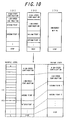
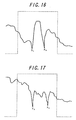
- Figs. 16 and 17 are diagrams for explaining the waveform model of the output signal of the light receiving element and show a model of the signal waveform when the wiper performs the first wiping after exit from the tunnel.
- a model of the signal waveform in the rainfall situation generally considered as heavy rain is shown.
- the inventors obtained the following finding. That is, a large motion appears in the signal waveform in the sections A and C.
- signal change hardly appears.
- Fig. 17 a model of the signal waveform in the rainfall situation generally considered as rainstorm whose rainfall is further larger than the heavy rain in Fig. 16 is shown.
- the inventors obtained the following finding. That is, a large motion appears in the signal waveform in the sections A, B and C.
- the third preferred embodiment of the present invention is to use such momentum of the signal waveform in the mask sections.
- the third preferred embodiment of the present invention is to detect raindrops from the output signal of the light receiving element in the mask section by determining the driving scene that a vehicle enters the rainfall shutoff environment such as a tunnel from a predetermined rainfall situation.
- adhesion of raindrops may be detected by comparing the momentum of the signal waveform in the mask section in the tunnel with the momentum of the signal waveform in the mask section after exit from the tunnel.
- the above-mentioned fluctuation of raindrops may be used for the evaluation of the momentum of the signal waveform.
- the number of change times of increase/decrease in the signal fluctuation, change amount of the increase/decrease and direction of increase/decrease of the change may be used.
- the length of fluctuation included in the signal fluctuation in the mask section in the tunnel, the number of change times of increase/decrease, the change amount of increase/decrease, etc. are acquired as the momentum of the signal waveform in the mask section in the tunnel.
- the length of fluctuation included in the signal fluctuation in the mask section after exit from the tunnel, the number of change times of increase/decrease, the change amount of increase/decrease, etc. are acquired as momentum of the signal waveform in the mask section after exit from the tunnel.
- Adhesion of raindrop after exit from the tunnel may be detected by comparing both of them.
- the wiping state control part 42 determines the driving scene that a vehicle enters the rainfall shutoff environment such as a tunnel from a certain rainfall situation. Since the vehicle is running in the tunnel at the time of this determination, the wiping state control part 42 next acquires the momentum of the signal waveform in the mask section and stores it. The wiping state control part 42 acquires the momentum of the signal waveform in the mask section at every wiping, compares it with the stored momentum and detects raindrops. In concrete, determination is made based on whether the length of fluctuation, number of change times of increase/decrease, the change amount of increase/decrease, etc. are larger than the momentum in the tunnel by a predetermined amount or not, and if larger by the predetermined amount, it may be detected as adhesion of raindrops. Also, the wiping state may be determined according to the amount exceeding the momentum in the tunnel.
- adhesion of raindrops may be detected in the signal waveform in a mask section under the condition that a predetermined momentum has been detected at least in the above A and C sections.
- dripping water a phenomenon that water is dripping from the roof of a vehicle or the like (hereinafter referred to as dripping water") can be observed.
- dripping water is temporary in many cases, it is not necessary to continue continuous wiping as in the rainfall case.
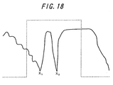
- Fig. 18 shows a waveform model of an output signal of a light receiving element when the dripping water passes through the detection surface. A finding was obtained that the signal waveform when the dripping water passes through the detection surface appears as a large momentum in the signal waveform only in the section A.
- the wiping state control part 42 determines the driving scene that a vehicle enters the raindrop shutoff environment such as a tunnel from a certain rainfall situation. Next the wiping state control part 42 determines if momentum is generated in the sections A and C for the signal waveform in the mask section. And when the momentum is generated in the sections A and C, adhesion of raindrops is detected so as to determine the wiping state according to the momentum.
- processing may be executed by detecting an event that a predetermined time has elapsed from exit from the tunnel and excluding the output signal of the light receiving element in the mask section from the objects for raindrop detection.
- Fig. 20 is a block diagram for explaining the configuration of the wiper control device according to the fourth preferred embodiment of the present invention in the layered structure.
- the wiper control device according to the fourth preferred embodiment of the present invention can be represented by three-layered construction, and between each of the layers, data or signals are made to communicate through a common interface such as SAP (service access point), for example.
- SAP service access point
- a first layer includes a rain sensor physical layer 190 and a vehicle control computer or a wiper motor 1100
- a second layer includes a raindrop detection part 122, a detection part 124 for a water amount collected by a wiper and an interface 126
- a third layer includes a wiping state control part 132 and a wiper stop control part 134. Each of them can be realized by software.
- the rain sensor physical layer 190 is comprised by an optical mechanism and a circuit, the optical mechanism being, for example, in the method that light from a light emitting element is reflected by a detection surface and a reflected light is received by a light receiving element and the circuits such as a filter circuit for processing output of the light receiving element, an amplifier circuit, an A/D converter, etc.
- the optical mechanism being, for example, in the method that light from a light emitting element is reflected by a detection surface and a reflected light is received by a light receiving element and the circuits such as a filter circuit for processing output of the light receiving element, an amplifier circuit, an A/D converter, etc.
- An example of such a rain sensor is disclosed in the JP-A-2001-180447 and the JP-A-2002-277386.
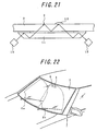
- Fig. 21 is a configuration diagram for explaining the configuration of the optical mechanism.
- a light emitting element 10 such as an LED
- a glass substrate windshield glass
- the led light is fully reflected by the surface to be detected 3 and enters a light receiving element 12 such as a photodiode, for example, through the above prism glass 11.
- the optical mechanism in this Fig. is arranged/constituted so that in the state of no adhesion of water drop or the like, the maximum output is generated at the light receiving element. At this time, if there is adhesion 13 of a water drop or the like on the detection surface, the output of the light receiving element is lowered.
- Fig. 22 is a view showing the installation positions of the detection surface on the windshield glass and the wiper control device.
- the wiper control device 1 has a part of the outer surface of the windshield glass 2 as the detection surface 3 and is mounted on the inner side of the windshield glass 2 of an automobile by an adhesive or the like, not shown.
- the installation position of the wiper control device 1 is arranged so that the set detection surface 3 is within a wiping operation range of one wiper 5b and outside the wiping operation range of the other wiper 5a.
- a vehicle control computer or wiper motor 1100 is connected to the wiper control device of the present invention and can be selected as appropriate according to the preferred embodiment of the present invention.
- the wiper motor is controlled through the vehicle control computer.
- the wiper motor is directly controlled.
- the raindrop detection part 122 detects raindrops based on the output signal of the light receiving element of the rain sensor.
- a method for detecting rain drops a method for detecting dynamic adhesion of raindrops (JP-A-2001-180447) and a method for evaluating fluctuation of an output signal of a light receiving element (JP-A-2002-277386) disclosed by the inventors may be used.
- a method for detecting raindrops a method for detecting raindrops in comparison with a reference value disclosed in JP-A-61-37560 (so-called threshold value method) and a method for detecting raindrops by an integrated value of the light receiving element output disclosed in JP-A-4-349053 (so-called integration method) may be also used.
- the detection part 124 for the amount of water collected by the wiper detects the amount of water carried by the wiper blade and passing through the detection surface (passing water amount) with wiping operation of the wiper.
- the interface 126 converts a wiper driving signal from the higher layer (third layer) to a signal in the format conforming to the vehicle control computer or the wiper motor, respectively.
- the wiping state control part 132 controls wiping state of the wiper based on the output of the raindrop detection part 122.
- the wiper wiping stage includes, for example, a stop state, an intermittent wiping state, a low-speed continuous wiping state and a high-speed continuous wiping state.
- the wiper wiping state is defined by the wiping waiting time and wiping speed.
- the wiping state control part 132 determines these wiping states and outputs a wiper driving signal of a predetermined wiping waiting time and a predetermined wiping speed.
- the wiper stop control part 134 controls stop of wiping of the wiper based on the output of the detection part 124 of the water amount collected by the wiper and the output of the raindrop detection part 122. In concrete, it is determined if the passing water amount is not less than a predetermined threshold value or not and if the passing water amount is at the predetermined threshold value or more and raindrops are not detected by the raindrop detection part 122, the wiper driving signal from the wiping state control part 132 is masked. On the other hand, if this condition is not applicable, the wiper driving signal is made to transmit. The wiper driving signal is outputted to the vehicle control computer or wiper motor 1100 through the interface 126.
- the wiping state control part 132 determines the wiping state independently based on the output of the raindrop detection part 122, while the wiper stop control part 134 executes stop control independently based on the output of the raindrop detection part 122 and the passing water amount.
- the wiping state control part 132 changes the wiping state among the stop state, intermittent wiping state, low-speed continuous wiping state and high-speed continuous wiping state according to the rainfall state (if intermittent wiping is divided into plural steps, transition is also made between the steps).
- the wiping state is defined stepwise by the wiping waiting time and wiping speed.
- the wiping waiting time also includes zero (that is, no waiting time). For example, the longer the wiping waiting time is, the longer the intermittence time, while if the wiping waiting time is zero, it means continuous wiping.
- the wiper stop control part 134 masks the wiper driving signal regardless of the wiping state of the wiping state control part 132. Therefore, a temporary stop state can be made separately from the stop state included in the wiping state. In the meantime, even if the wiper driving signal is masked, the wiping state control part 132 is functioning effectively, and if raindrops are detected, the wiping state can be determined according to it and a predetermined wiper driving signal can be outputted.
- the raindrop detection part 122 uses, as a method for detecting raindrops, a method for detecting dynamic adhesion of raindrops (JP-A-2001-180447) and a method for evaluating fluctuation of an output signal of a light receiving element (JP-A-2002-277386).
- the method for detecting dynamic adhesion of raindrops disclosed by the inventors (JP-A-2001-180447) generates a delay signal form a signal from the light receiving elements, acquires a difference between the signal from the light receiving element and the delay signal and determines it as there was a collision of water drops on the detection surface when a difference is generated.
- a primary delay signal of the signal from the light receiving element is generated, a secondary delay signal is generated from the primary delay signal, a difference between the primary delay signal and the secondary delay signal is acquired and determines it as there was a collision of water drops on the detection surface when a difference is generated.
- the raindrop detection part 122 detects the phenomenon of a collision of raindrops on the detection surface and outputs it as adhesion of raindrops.
- the wiping state control part 132 judges an adhesion cycle of raindrops based on the adhesion of raindrops and determines the wiping state of the wiper based on this. For example, when a long adhesion cycle is detected, a long intermittence time is determined as the wiping state. As the adhesion cycle gets shorter, the intermittence time is made shorter. Alternatively, as mentioned above, when the adhesion cycle is changed, the current intermittence time is maintained for a predetermined preliminary wiping period or till the preliminary wiping number of times is finished, and the intermittence time is changed after that.
- the wiping state control part 132 determines the wiping state also by the size of the adhering raindrop in addition to the adhesion cycle. A method for estimating the size of the raindrop is shown hereinafter.
- JP-A-2002-277386 disclosed by the inventors is used.
- This method can indirectly detect dynamic fluctuation of an adhering object by dynamic fluctuation of a signal of the light receiving element obtained through the adhering object adhering on the detection surface, and moreover, this method can determine what the adhering object is and in what state the adhering object is by detecting the change pattern of fluctuation of the adhering object indirectly determined by physical properties through the change pattern of the fluctuation of the signal.
- the change pattern of the fluctuation of the signal used in the above determination can be the change pattern of the time of fluctuation of the above signal, and the length of the fluctuation of the adhering object can be detected indirectly by the length of the fluctuation of the signal. For example, if the adhering object is a raindrop, the larger the raindrop is, the longer the fluctuation lasts as its physical properties, and the size of the raindrop can be estimated by the detected length of the fluctuation.
- the change pattern of the fluctuation of the signal used in the above determination can be the change pattern of the size of the fluctuation of the above signal, and the size of the fluctuation of the adhering object can be detected indirectly by the size of the fluctuation of the signal.
- the adhering object is a raindrop
- the size of the raindrop can be estimated by the detected size of the fluctuation.
- Parameters representing the size of fluctuation include the number of change times of increase/decrease within the fluctuation, change amount of the increase, direction of increase/decrease of the change, etc.
- the raindrop detection part 122 detects and outputs the change pattern of the signal fluctuation.
- the length of the signal fluctuation, the number of change times of increase/decrease within the signal fluctuation, the change amount of increase, direction of increase/decrease of the change, etc. are outputted.
- the wiping state control part 132 determines the size of the raindrops from the change pattern of the detected signal fluctuation based on this table.
- the wiping state control part 132 may determine the wiping state by judging the intensity of raindrops hitting the windshield glass and identifying if the rain situation is heavy or not. The inventors obtained the finding that the momentum after adhesion of raindrops is changed depending on how the raindrops hit the windshield glass. In concrete, the harder the raindrops hit the windshield glass, the larger the momentum of the raindrops becomes after adhesion.
- the momentum of raindrops here can be represented by the length and size of the signal fluctuation.
- the length of fluctuation is the time till the size of the fluctuation is attenuated to a predetermined size after adhesion of the raindrops.
- the size of fluctuation is represented by parameters such as the number of change times of increase/decrease in the fluctuation, the change amount of increase, direction of increase/decrease, etc.
- the increase in size of the fluctuation can be represented by parameters such as increase in the number of change times of increase/decrease and in the change amount of increase and decrease in the increase/decrease direction of the change.
- the change amount in the decrease direction of the signal at adhesion is the same.
- the number of change times of increase/decrease after the adhesion and the change amount of increase are increased and the length of the fluctuation gets longer. Based on this finding, the intensity of hitting of raindrops can be associated with the change pattern of signal fluctuation characterized by the length and the size of the signal fluctuation.
- the wiping state control part 132 determines the intensity of hitting of the raindrops by evaluating the fluctuation of the signal from the raindrop detection part 122 using such a table. (Another method for determining wiping state)
- the rainfall situation can be classified in detail by using the number of adhering raindrops per unit time or continuity of adhesion, the size of adhering raindrop and the way of hitting of the raindrops as parameters.
- the wiping state control part 132 determines these parameters including the number of adhering raindrops per unit time or continuity of adhesion, the size of adhering raindrop and the way of hitting of the raindrops from the output of the raindrop detection part 122, distinguishes the current rainfall situation in detail using these parameters and selects the wiping state set for each of the rainfall situation.
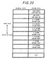
- Fig. 23 An example of a table in which the rainfall states and corresponding wiping states are set is shown in Fig. 23.
- the rainfall states are classified into a plurality of levels, and a wiping state corresponding to each of the levels is set.
- the wiping state control part 132 determines the level to which the rainfall state is applicable using the above parameters and selects the wiping state of the applicable level. Alternatively, the wiping state is changed stepwise from the current wiping state to the selected wiping state.
- the long and large fluctuation generally means that the raindrop is large and it is heavy rain.
- control is executed to reduce the intermittence time or to increase the driving speed of the wiper.
- the small and short fluctuation generally means that the raindrop is small and it is drizzling rain.
- control is preferable to extend the intermittence time or to decrease the driving speed of the wiper.
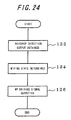
- Figs. 24 and 25 are flowcharts for explaining the operation of the wiper control device according to the fourth preferred embodiment of the present invention
- Fig. 26 is a conceptual diagram explaining the detection section.
- the wiping state control part 132 first at Step 122, obtains an output of the raindrop detection part 122 in a unit detection section.
- the unit detection section is made of, for example, combination of a waiting time T of the wiper and the subsequent wiper operating time (A/S ON) as shown in Fig. 26.
- A/S ON the subsequent wiper operating time
- the signal change when the wiper blade passes through the detection surface is extremely large, and the detection signal is masked at passage of the wiper blade.
- the wiping state is determined.
- the current wiping state is recognized, and transition is made to a required wiping state based on the output of the raindrop detection part 122. For example, transition is made from the stop state to the intermittent wiping state, or from the low-speed continuous wiping state to the intermittent wiping state.
- a wiper (WP) driving signal of a predetermined wiping speed is outputted per predetermined wiping waiting time.
- the wiper stop control part 134 first, at Step 132, obtains the passing water amount in the unit detection section.
- the wiper blade passes through the detection surface in the detection mask section, and the passing water amount is detected in this section.
- the passing water amount can be a peak value of the signal change in the detection mask section.
- Step 134 it is determined if the detected passing water amount is not smaller than the predetermined threshold value th or not. If the passing water amount is larger than the predetermined threshold value th, it is determined at Step 136 if the raindrops are detected in the unit detection section or not, and if raindrops are not detected, the routine goes to Step 138, where the wiper driving signal is masked. On the other hand, if the detected passing water amount is less than the predetermined threshold value th at Step 134, or if raindrops are detected in the unit detection section at Step 136, the routine goes to Step 140, where the wiper driving signal is made to transmit.
- Fig. 27 is a diagram for explaining the application example of the present invention.
- the raindrop detection part 122 keeps on detecting raindrops, and the wiping state control part 132 determines the wiping state as an intermittent wiping with 1-second waiting time, for example. Based on this intermittent wiping, a wiper driving signal s is outputted in a predetermined cycle.
- the raindrops are not detected any more after entrance to the tunnel, and the wiping state control part 132 changes the wiping state to the intermittent wiping state with longer waiting time (2 seconds), which makes the output cycle of the wiper driving signal s longer.
- the intermittent state is made to transit after predetermined preliminary wiping. After that, if the state where no raindrop is detected continues, the wiping state is made to transit to the stop state.
- the vehicle exits from the tunnel at the stage that the wiping state is in the 2-second intermittent wiping state, and raindrops are detected again.
- the wiping state control part 132 changes the wiping state from the 2-second intermittent wiping to 1-second intermittent wiping.
- the wiper stop control part 134 identifies the passing water amount ⁇ threshold value th before entrance to the tunnel, but since raindrops are detected, the wiper driving signal is made to transmit. Next, when detection of raindrops is stopped by entrance to the tunnel and dripping water is supplied to the wiper blade, which establishes determination of passing water amount ⁇ threshold value th, the wiper stop control part 134 masks the wiper driving signal. When the raindrops are detected again after exit from the tunnel, the wiper stop control part 134 allows the wiper driving signal to transmit.
- Fig. 28 is a flowchart for explaining the flow of the control processing
- Fig. 29 for explaining the relation between the wiper operation signal and a passing water amount detection timing
- Fig. 30 for explaining the relation among the passing water amount, waiting time and the point value.
- the wiper stop control part 134 is started at the timing when the wiper is retuned to the original position and integrates the passing water amount detected by this wiping in a counter (Step 301).
- integration of actual passing water amount itself is not adopted.
- a value of the passing water amount a predetermined point value determined by combination of the actual passing water amount and the wiper waiting time is used. This point value will be described below.
- the wiper is operated in a period when the operation signal is ON (operation period) and stands by in a period when the operation signal is OFF (waiting period).
- the operation periods are indicated as OP1, OP2 and OP3, while the waiting periods as W1, W2 and W3.
- W1, W2 and W3 are periods with different length of time (W1 ⁇ W2 ⁇ W3).
- the passing water amount is detected from the signal in the operation period.
- the wiper stop control part 134 refers to the waiting period immediately before the operation period in which the passing water amount is detected. Then, the point value is determined from the combination of the value of the passing water amount and the length of the waiting period.
- the matrix in Fig. 30, for example is used to determine the point value. In the matrix in Fig. 30, the point value is arranged so that it is increased in proportion to the increase of the passing water amount and decreased in reverse proportion to the increase of the waiting period.
- the water amount of th1 is obtained in the first operation period OP1.
- the waiting period immediately before OP1 is W1.
- W1 and th1 in the matrix in Fig. 30 the point value of 6 is obtained.
- the point value 6 thus obtained is integrated to the counter. For example, if the previous point remains in the counter, the value is integrated to this.
- the wiper stop control part 134 determines if adhesion of raindrops on the detection surface is detected by the raindrop detection part 122 or not (Step 302). Detection of raindrop adhesion is conducted by above mentioned methods and the detection results are stored in a predetermined memory.
- the counter to which the point value was integrated is cleared to zero (Step 303). Alternatively, the counter is reset to a designated value.
- the wiper stop control part 134 determines if the counter value is not smaller than a threshold value Wt (Step 304).
- the counter value less than the threshold value Wt includes the case where the counter integration value (6 points in the above example) itself is smaller than the threshold value Wt and the case where the counter is cleared at the above step 303.
- Step 304 if the counter value is at the threshold value Wt or more, the wiper driving signal is masked (Step 305), while if the counter value is less than the threshold value Wt, the wiper driving signal is made to transmit (Step 306).
- the counter value at the threshold value Wt or more at Step 304 means the case where adhesion of raindrops is not detected even though the passing water amount is more than predetermined.
- the present invention can be brought into practice using small CPU load and a small memory capacity.
- the sixth preferred embodiment of the present invention controls timing of wiping stop. Based on consideration by the inventors, it was found out, in the case where wiping by a wiper is to be stopped based on the premise that adhesion of raindrops is not detected, there is a case where it is preferable to stop after wiping is continued to some extent and a case where wiping is preferably stopped quickly.
- timing till wiping is stopped (masked) from detection of the state without adhesion is controlled according to the value of the passing water amount.
- the number of wiping times till wiping stop is controlled.
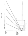
- Fig. 31 is a conceptual diagram for explaining the relation between the passing water amount when the wiper waiting time is T and the point.
- Fig. 32 is a conceptual diagram for explaining the covering rate of the raindrops over the windshield.
- the allocated point values are changed by the value of the passing water amount. In this way, by changing the point value to be allocated to the detected single passing water amount, the number of wiping times (number of detection times) required till the WP driving signal is masked can be controlled.
- a maximum point is set in the N band.
- Wt or more is gained by one determination, and the wiper driving signal is masked immediately.
- a minimum point is set in the M band. In the case of this minimum point, Wt is reached only after plural times of integration, and plural times of wiping will be continued. If sensitivity adjustment is made by sensitivity volume or the like, the threshold value Wt is preferably changed according to this.
- the passing water amount in the N band immediately masks the wiper driving signal as a value which cannot be determined as a passing water amount by adhesion of raindrops or wetting of the wiper blade. That is because even if there is any adhesion of raindrops, it should be determined as extremely small and there is no need for intermittent operation.
- the detected passing water amount is not likely to generate adhesion of raindrops in the wiper waiting time, and if plural times of wiping are ensured and there is no adhesion of raindrops during the plural times of wiping, it is determined as the rainfall becomes weak or disappears.
- the M band continuity is given importance than stop, and the maximum times of wiping are ensured.
- adhesion of the passing water cannot be easily detected even if the rainfall is at a certain level. Then, it is appropriate to determine it as not being caused by rainfall only if the state of no detection of adhesion lasts long.
- the passing water amount which can expect a good possibility of adhesion of raindrops during the wiper waiting time. Then, if plural times of wiping are ensured and there is no adhesion of raindrops during the plural time, the passing water amount is determined as not being caused by rainfall. Finally, in the L band, the passing water amount to permit adhesion of raindrops during the wiper waiting time, and if plural times of wiping are ensured and there is no adhesion of raindrops during the plural times, the passing water amount is determined as not being caused by rainfall.
- the relation for the waiting time T was explained. Ideally, the above relation is considered to be fixed in every waiting time. That is because, as shown in the graph in Fig. 32, even if waiting time is changed, the covering rate with which the driver wants to wipe is expected to be constant. Also, if the covering rate is constant, the amount of raindrops on the windshield is constant and the value of the passing water amount collecting this also becomes constant.
- the wiper can be stopped at an appropriate timing according to the rainfall situation.
- change of the rainfall situation can be smoothly responded.
- a rapid change in the rainfall situation at passage of the rainfall shutoff environment such as in a tunnel can be smoothly responded.
- wiping by a wiper can appropriately follow the change in the rainfall situation.
- the wiping by the wiper can be stopped in a short time when entering a tunnel, while a wiping frequency can be increased to an appropriate level at exit from the tunnel in a short time.
Landscapes
- Engineering & Computer Science (AREA)
- Mechanical Engineering (AREA)
- Life Sciences & Earth Sciences (AREA)
- Environmental & Geological Engineering (AREA)
- Automation & Control Theory (AREA)
- Physics & Mathematics (AREA)
- Chemical & Material Sciences (AREA)
- Biodiversity & Conservation Biology (AREA)
- Ecology (AREA)
- Environmental Sciences (AREA)
- Hydrology & Water Resources (AREA)
- Health & Medical Sciences (AREA)
- Atmospheric Sciences (AREA)
- Analytical Chemistry (AREA)
- Biochemistry (AREA)
- General Health & Medical Sciences (AREA)
- General Physics & Mathematics (AREA)
- Immunology (AREA)
- Pathology (AREA)
- Investigating Or Analysing Materials By Optical Means (AREA)
Applications Claiming Priority (3)
| Application Number | Priority Date | Filing Date | Title |
|---|---|---|---|
| JP2003136893A JP4259916B2 (ja) | 2003-05-15 | 2003-05-15 | ワイパー制御方法、およびワイパー制御装置 |
| JP2003136874A JP2004338523A (ja) | 2003-05-15 | 2003-05-15 | ワイパー制御方法、およびワイパー制御装置 |
| PCT/JP2004/006783 WO2004101333A1 (ja) | 2003-05-15 | 2004-05-13 | ワイパー制御方法、およびワイパー制御装置 |
Publications (2)
| Publication Number | Publication Date |
|---|---|
| EP1623896A1 true EP1623896A1 (de) | 2006-02-08 |
| EP1623896A4 EP1623896A4 (de) | 2006-06-14 |
Family
ID=33455471
Family Applications (1)
| Application Number | Title | Priority Date | Filing Date |
|---|---|---|---|
| EP04732785A Withdrawn EP1623896A4 (de) | 2003-05-15 | 2004-05-13 | Verfahren und vorrichtung zur scheibenwischersteuerung |
Country Status (4)
| Country | Link |
|---|---|
| US (1) | US7466097B2 (de) |
| EP (1) | EP1623896A4 (de) |
| KR (1) | KR20060023126A (de) |
| WO (1) | WO2004101333A1 (de) |
Cited By (1)
| Publication number | Priority date | Publication date | Assignee | Title |
|---|---|---|---|---|
| US7772793B2 (en) | 2006-12-28 | 2010-08-10 | Denso Corporation | Raindrop detecting device and method of selecting wiping mode for vehicle |
Families Citing this family (8)
| Publication number | Priority date | Publication date | Assignee | Title |
|---|---|---|---|---|
| KR100981216B1 (ko) | 2008-08-20 | 2010-09-10 | 한국오므론전장주식회사 | 속도 감응형 레인센서 |
| JP5525976B2 (ja) * | 2010-09-10 | 2014-06-18 | 株式会社デンソー | ワイパ制御装置 |
| US9045112B2 (en) | 2013-03-15 | 2015-06-02 | Honda Motor Co., Ltd. | Adjustable rain sensor setting based on proximity vehicle detection |
| JP6349120B2 (ja) * | 2014-03-27 | 2018-06-27 | 株式会社ミツバ | ワイパシステム制御方法及びワイパシステム制御装置 |
| JP2020006886A (ja) * | 2018-07-11 | 2020-01-16 | 株式会社デンソー | 降雨量計測装置 |
| CN114368358A (zh) * | 2022-01-17 | 2022-04-19 | 广州小鹏汽车科技有限公司 | 雨刮器补刮控制方法、装置、车辆以及存储介质 |
| CN114633723A (zh) * | 2022-01-25 | 2022-06-17 | 中国第一汽车股份有限公司 | 一种汽车控制雨刮的方法及汽车 |
| CN114670787B (zh) * | 2022-03-07 | 2023-10-20 | 岚图汽车科技有限公司 | 车辆、雨刮器的控制方法和相关设备 |
Family Cites Families (18)
| Publication number | Priority date | Publication date | Assignee | Title |
|---|---|---|---|---|
| JPS61191961U (de) * | 1985-05-23 | 1986-11-29 | ||
| US4859867A (en) * | 1988-04-19 | 1989-08-22 | Donnelly Corporation | Windshield moisture sensing control circuit |
| US5216341A (en) * | 1988-12-19 | 1993-06-01 | Fujitsu Ten Limited | Windshield wiper control apparatus |
| US4916374A (en) * | 1989-02-28 | 1990-04-10 | Donnelly Corporation | Continuously adaptive moisture sensor system for wiper control |
| DE3926175C1 (de) * | 1989-08-08 | 1990-09-13 | Mercedes-Benz Aktiengesellschaft, 7000 Stuttgart, De | |
| US5059877A (en) * | 1989-12-22 | 1991-10-22 | Libbey-Owens-Ford Co. | Rain responsive windshield wiper control |
| JPH0396253U (de) * | 1990-01-24 | 1991-10-01 | ||
| US5276388A (en) * | 1991-12-14 | 1994-01-04 | Leopold Kostal Gmbh & Co. Kg | Apparatus and method for controlling a windshield wiping system |
| KR100302088B1 (ko) * | 1993-07-02 | 2001-12-28 | 게르트 라이메 | 배면방사요소의 변동검지장치 |
| JPH078118U (ja) * | 1993-07-14 | 1995-02-03 | 自動車電機工業株式会社 | ワイパ制御装置 |
| JPH0995217A (ja) * | 1995-09-28 | 1997-04-08 | Omron Corp | ワイパ駆動装置 |
| EP1147031B1 (de) * | 1999-01-25 | 2011-12-28 | Gentex Corporation | Steuerung von fahrzeuggeräten mit halbleiterlichtsensoren |
| JP3775183B2 (ja) * | 2000-08-07 | 2006-05-17 | 日産自動車株式会社 | ワイパー駆動装置の制御方法 |
| JP4668446B2 (ja) * | 2001-03-29 | 2011-04-13 | 株式会社デンソー | ワイパ制御システム |
| JP2003002171A (ja) * | 2001-06-19 | 2003-01-08 | Nissan Motor Co Ltd | ワイパー制御装置 |
| DE10242688A1 (de) * | 2002-09-13 | 2004-03-25 | Robert Bosch Gmbh | Regensensor, insbesondere für ein Kraftfahrzeug mit einer Scheibenwischvorrichtung sowie Verfahren zum Steuern einer Scheibenwischvorrichtung |
| JP4175266B2 (ja) * | 2004-02-06 | 2008-11-05 | 株式会社デンソー | ワイパ装置 |
| JP4389692B2 (ja) * | 2004-06-24 | 2009-12-24 | 株式会社デンソー | 雨滴検出装置 |
-
2004
- 2004-05-13 EP EP04732785A patent/EP1623896A4/de not_active Withdrawn
- 2004-05-13 WO PCT/JP2004/006783 patent/WO2004101333A1/ja not_active Ceased
- 2004-05-13 KR KR1020057021806A patent/KR20060023126A/ko not_active Withdrawn
- 2004-05-13 US US10/556,760 patent/US7466097B2/en not_active Expired - Fee Related
Cited By (1)
| Publication number | Priority date | Publication date | Assignee | Title |
|---|---|---|---|---|
| US7772793B2 (en) | 2006-12-28 | 2010-08-10 | Denso Corporation | Raindrop detecting device and method of selecting wiping mode for vehicle |
Also Published As
| Publication number | Publication date |
|---|---|
| US20070132417A1 (en) | 2007-06-14 |
| KR20060023126A (ko) | 2006-03-13 |
| US7466097B2 (en) | 2008-12-16 |
| EP1623896A4 (de) | 2006-06-14 |
| WO2004101333A1 (ja) | 2004-11-25 |
Similar Documents
| Publication | Publication Date | Title |
|---|---|---|
| US7772793B2 (en) | Raindrop detecting device and method of selecting wiping mode for vehicle | |
| US6262410B1 (en) | Moisture sensor and windshield fog detector | |
| US7612356B2 (en) | Raindrop sensor for detecting rain on a vehicle windshield including an image sensor and processor for performing a frequency analysis of an image and wiper controller having the same | |
| CN100420592C (zh) | 自动汽车外部灯光控制系统 | |
| CN100491170C (zh) | 用于车辆自动刮擦的刮水器控制设备和方法 | |
| US7466097B2 (en) | Wiper control method and wiper control device | |
| CN115503649B (zh) | 一种汽车自动雨刮控制系统和方法 | |
| US7576658B2 (en) | Wiper control device for vehicle | |
| EP1495928B1 (de) | Verfahren zur steuerung eines wischers und wischersteuerung | |
| KR100659227B1 (ko) | 차량 앞유리 와이퍼를 제어하기 위한 와이퍼 제어장치 | |
| JP4259916B2 (ja) | ワイパー制御方法、およびワイパー制御装置 | |
| JP4259915B2 (ja) | ワイパー制御方法、およびワイパー制御装置 | |
| JP2004338523A (ja) | ワイパー制御方法、およびワイパー制御装置 | |
| JP2003002171A (ja) | ワイパー制御装置 | |
| JPH115514A (ja) | ワイパー自動制御装置 | |
| EP1637416A1 (de) | Verfahren und vorrichtung zur scheibenwischersteuerung | |
| CN114987391B (zh) | 一种提高自动雨刮感应效果的方法和系统 | |
| JPH04221253A (ja) | ワイパー制御装置 | |
| CN120481926A (zh) | 一种雨刮软件车速降档算法 | |
| JPH08164825A (ja) | ワイパ装置 | |
| JPH09109840A (ja) | 車両用ワイパ制御装置 | |
| JPS6223850A (ja) | 車両用ワイパ制御装置 | |
| CN121133615A (zh) | 一种汽车前挡风玻璃清洁系统和方法 |
Legal Events
| Date | Code | Title | Description |
|---|---|---|---|
| PUAI | Public reference made under article 153(3) epc to a published international application that has entered the european phase |
Free format text: ORIGINAL CODE: 0009012 |
|
| 17P | Request for examination filed |
Effective date: 20051123 |
|
| AK | Designated contracting states |
Kind code of ref document: A1 Designated state(s): AT BE BG CH CY CZ DE DK EE ES FI FR GB GR HU IE IT LI LU MC NL PL PT RO SE SI SK TR |
|
| A4 | Supplementary search report drawn up and despatched |
Effective date: 20060428 |
|
| DAX | Request for extension of the european patent (deleted) | ||
| 17Q | First examination report despatched |
Effective date: 20070626 |
|
| STAA | Information on the status of an ep patent application or granted ep patent |
Free format text: STATUS: THE APPLICATION IS DEEMED TO BE WITHDRAWN |
|
| 18D | Application deemed to be withdrawn |
Effective date: 20110614 |