EP1624171B1 - Vorrichtung und Methode zur Steuerung einer Brennkraftmaschine - Google Patents
Vorrichtung und Methode zur Steuerung einer Brennkraftmaschine Download PDFInfo
- Publication number
- EP1624171B1 EP1624171B1 EP05254810A EP05254810A EP1624171B1 EP 1624171 B1 EP1624171 B1 EP 1624171B1 EP 05254810 A EP05254810 A EP 05254810A EP 05254810 A EP05254810 A EP 05254810A EP 1624171 B1 EP1624171 B1 EP 1624171B1
- Authority
- EP
- European Patent Office
- Prior art keywords
- internal combustion
- combustion engine
- control
- clutch
- torque
- Prior art date
- Legal status (The legal status is an assumption and is not a legal conclusion. Google has not performed a legal analysis and makes no representation as to the accuracy of the status listed.)
- Ceased
Links
- 238000002485 combustion reaction Methods 0.000 title claims description 49
- 238000000034 method Methods 0.000 title claims description 25
- 230000005540 biological transmission Effects 0.000 claims description 62
- 230000003247 decreasing effect Effects 0.000 claims description 13
- 230000035939 shock Effects 0.000 description 15
- 230000004044 response Effects 0.000 description 11
- 239000000446 fuel Substances 0.000 description 6
- 239000003054 catalyst Substances 0.000 description 5
- 238000010586 diagram Methods 0.000 description 5
- 230000007423 decrease Effects 0.000 description 4
- 238000001514 detection method Methods 0.000 description 4
- 230000002542 deteriorative effect Effects 0.000 description 3
- 239000000203 mixture Substances 0.000 description 3
- 239000002826 coolant Substances 0.000 description 1
- 230000000994 depressogenic effect Effects 0.000 description 1
- 230000006870 function Effects 0.000 description 1
- 239000010720 hydraulic oil Substances 0.000 description 1
- 230000000979 retarding effect Effects 0.000 description 1
Images


Classifications
-
- F—MECHANICAL ENGINEERING; LIGHTING; HEATING; WEAPONS; BLASTING
- F02—COMBUSTION ENGINES; HOT-GAS OR COMBUSTION-PRODUCT ENGINE PLANTS
- F02P—IGNITION, OTHER THAN COMPRESSION IGNITION, FOR INTERNAL-COMBUSTION ENGINES; TESTING OF IGNITION TIMING IN COMPRESSION-IGNITION ENGINES
- F02P5/00—Advancing or retarding ignition; Control therefor
- F02P5/04—Advancing or retarding ignition; Control therefor automatically, as a function of the working conditions of the engine or vehicle or of the atmospheric conditions
- F02P5/145—Advancing or retarding ignition; Control therefor automatically, as a function of the working conditions of the engine or vehicle or of the atmospheric conditions using electrical means
- F02P5/15—Digital data processing
- F02P5/1502—Digital data processing using one central computing unit
- F02P5/1504—Digital data processing using one central computing unit with particular means during a transient phase, e.g. acceleration, deceleration, gear change
-
- B—PERFORMING OPERATIONS; TRANSPORTING
- B60—VEHICLES IN GENERAL
- B60W—CONJOINT CONTROL OF VEHICLE SUB-UNITS OF DIFFERENT TYPE OR DIFFERENT FUNCTION; CONTROL SYSTEMS SPECIALLY ADAPTED FOR HYBRID VEHICLES; ROAD VEHICLE DRIVE CONTROL SYSTEMS FOR PURPOSES NOT RELATED TO THE CONTROL OF A PARTICULAR SUB-UNIT
- B60W30/00—Purposes of road vehicle drive control systems not related to the control of a particular sub-unit, e.g. of systems using conjoint control of vehicle sub-units
- B60W30/18—Propelling the vehicle
- B60W30/19—Improvement of gear change, e.g. by synchronisation or smoothing gear shift
-
- F—MECHANICAL ENGINEERING; LIGHTING; HEATING; WEAPONS; BLASTING
- F02—COMBUSTION ENGINES; HOT-GAS OR COMBUSTION-PRODUCT ENGINE PLANTS
- F02D—CONTROLLING COMBUSTION ENGINES
- F02D37/00—Non-electrical conjoint control of two or more functions of engines, not otherwise provided for
- F02D37/02—Non-electrical conjoint control of two or more functions of engines, not otherwise provided for one of the functions being ignition
-
- F—MECHANICAL ENGINEERING; LIGHTING; HEATING; WEAPONS; BLASTING
- F02—COMBUSTION ENGINES; HOT-GAS OR COMBUSTION-PRODUCT ENGINE PLANTS
- F02D—CONTROLLING COMBUSTION ENGINES
- F02D41/00—Electrical control of supply of combustible mixture or its constituents
- F02D41/02—Circuit arrangements for generating control signals
- F02D41/021—Introducing corrections for particular conditions exterior to the engine
- F02D41/0215—Introducing corrections for particular conditions exterior to the engine in relation with elements of the transmission
- F02D41/022—Introducing corrections for particular conditions exterior to the engine in relation with elements of the transmission in relation with the clutch status
-
- F—MECHANICAL ENGINEERING; LIGHTING; HEATING; WEAPONS; BLASTING
- F02—COMBUSTION ENGINES; HOT-GAS OR COMBUSTION-PRODUCT ENGINE PLANTS
- F02D—CONTROLLING COMBUSTION ENGINES
- F02D41/00—Electrical control of supply of combustible mixture or its constituents
- F02D41/02—Circuit arrangements for generating control signals
- F02D41/021—Introducing corrections for particular conditions exterior to the engine
- F02D41/0215—Introducing corrections for particular conditions exterior to the engine in relation with elements of the transmission
- F02D41/023—Introducing corrections for particular conditions exterior to the engine in relation with elements of the transmission in relation with the gear ratio shifting
-
- B—PERFORMING OPERATIONS; TRANSPORTING
- B60—VEHICLES IN GENERAL
- B60W—CONJOINT CONTROL OF VEHICLE SUB-UNITS OF DIFFERENT TYPE OR DIFFERENT FUNCTION; CONTROL SYSTEMS SPECIALLY ADAPTED FOR HYBRID VEHICLES; ROAD VEHICLE DRIVE CONTROL SYSTEMS FOR PURPOSES NOT RELATED TO THE CONTROL OF A PARTICULAR SUB-UNIT
- B60W10/00—Conjoint control of vehicle sub-units of different type or different function
- B60W10/04—Conjoint control of vehicle sub-units of different type or different function including control of propulsion units
- B60W10/06—Conjoint control of vehicle sub-units of different type or different function including control of propulsion units including control of combustion engines
-
- B—PERFORMING OPERATIONS; TRANSPORTING
- B60—VEHICLES IN GENERAL
- B60W—CONJOINT CONTROL OF VEHICLE SUB-UNITS OF DIFFERENT TYPE OR DIFFERENT FUNCTION; CONTROL SYSTEMS SPECIALLY ADAPTED FOR HYBRID VEHICLES; ROAD VEHICLE DRIVE CONTROL SYSTEMS FOR PURPOSES NOT RELATED TO THE CONTROL OF A PARTICULAR SUB-UNIT
- B60W2510/00—Input parameters relating to a particular sub-units
- B60W2510/02—Clutches
- B60W2510/0208—Clutch engagement state, e.g. engaged or disengaged
-
- B—PERFORMING OPERATIONS; TRANSPORTING
- B60—VEHICLES IN GENERAL
- B60W—CONJOINT CONTROL OF VEHICLE SUB-UNITS OF DIFFERENT TYPE OR DIFFERENT FUNCTION; CONTROL SYSTEMS SPECIALLY ADAPTED FOR HYBRID VEHICLES; ROAD VEHICLE DRIVE CONTROL SYSTEMS FOR PURPOSES NOT RELATED TO THE CONTROL OF A PARTICULAR SUB-UNIT
- B60W2710/00—Output or target parameters relating to a particular sub-units
- B60W2710/06—Combustion engines, Gas turbines
- B60W2710/0605—Throttle position
-
- B—PERFORMING OPERATIONS; TRANSPORTING
- B60—VEHICLES IN GENERAL
- B60W—CONJOINT CONTROL OF VEHICLE SUB-UNITS OF DIFFERENT TYPE OR DIFFERENT FUNCTION; CONTROL SYSTEMS SPECIALLY ADAPTED FOR HYBRID VEHICLES; ROAD VEHICLE DRIVE CONTROL SYSTEMS FOR PURPOSES NOT RELATED TO THE CONTROL OF A PARTICULAR SUB-UNIT
- B60W2710/00—Output or target parameters relating to a particular sub-units
- B60W2710/06—Combustion engines, Gas turbines
- B60W2710/0666—Engine torque
-
- Y—GENERAL TAGGING OF NEW TECHNOLOGICAL DEVELOPMENTS; GENERAL TAGGING OF CROSS-SECTIONAL TECHNOLOGIES SPANNING OVER SEVERAL SECTIONS OF THE IPC; TECHNICAL SUBJECTS COVERED BY FORMER USPC CROSS-REFERENCE ART COLLECTIONS [XRACs] AND DIGESTS
- Y02—TECHNOLOGIES OR APPLICATIONS FOR MITIGATION OR ADAPTATION AGAINST CLIMATE CHANGE
- Y02T—CLIMATE CHANGE MITIGATION TECHNOLOGIES RELATED TO TRANSPORTATION
- Y02T10/00—Road transport of goods or passengers
- Y02T10/10—Internal combustion engine [ICE] based vehicles
- Y02T10/40—Engine management systems
Definitions
- the control means performs the torque control by the method including changing the ignition timing of the internal combustion engine and changing the flow rate of air introduced into the internal combustion engine, and the torque control that is performed by the method of changing the ignition timing is prohibited, for example, in the case where the clutch is in the engaged state when shifting of the automatic transmission is performed.
- the torque is controlled, for example, by a method of changing only the flow rate of the air.
- the air flow rate control means includes means for performing the torque control so that the torque of the internal combustion engine is decreased.
- control means includes means for performing the torque control for the internal combustion engine by a method of changing the flow rate of the air and the ignition timing when the clutch is in a disengaged state.
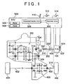
- the ECU 500 performs computation based on the signals sent from the aforementioned sensors, the programs and maps stored in the ROM 506, and the like. In this embodiment, the ECU 500 performs shifting (upshifting and downshifting) based on the shift operation performed by the driver. The ECU 500 may perform shifting based on operation of a switch provided in a steering wheel (not shown), instead of the shift operation.
- the air introduced into the combustion chamber is controlled by a throttle valve 116.
- the throttle valve 116 is an electronically controlled throttle valve that is driven by a motor.
- An opening amount of the throttle valve 116 is controlled by the ECU 500.
- a flow rate of air is detected by an air flow meter 526, and a signal indicative of the result of detection is sent to the ECU 500.
- the opening amount of the throttle valve 116 is detected by a throttle opening amount sensor 528, and a signal indicative of the result of detection is sent to the ECU 500.
- a temperature TC of the catalyst 114 is detected by a temperature sensor 530, and a signal indicative of the result of detection is sent to the ECU 500.
- the catalyst temperature TC may be estimated based on the engine rotational speed, the load, a temperature of coolant, a temperature of intake air, and the like, instead of detecting the catalyst temperature TC using the temperature sensor 530.
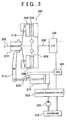
- the clutch 200 is a dry type single plate friction clutch. As shown in FIG. 3 , the clutch 200 includes a clutch output shaft 202, a clutch disk 204 provided on the clutch output shaft 202, a clutch housing 206, a pressure plate 208 provided in the clutch housing 206, a diaphragm spring 210, a clutch release cylinder 212, a release fork 214, and a release sleeve 216.
- the clutch release cylinder 212 is operated when hydraulic pressure of hydraulic oil pumped up by a hydraulic pump 220 from a reservoir 218 is supplied to the clutch release cylinder 212 via a clutch solenoid valve 222.
- the clutch solenoid valve 222 switches between supply of the hydraulic pressure to the clutch release cylinder 212 and discharge of the hydraulic pressure from the clutch release cylinder 212.
- the clutch solenoid valve 222 is controlled by the ECU 500.
- the ECU 500 detects whether the clutch 200 is in a disengaged state, in an engaged state, or in a semi-engaged state, based on the signal sent from the clutch stroke sensor 536.
- the clutch 200 may be operated by electric power.
- step S 100 the ECU 500 determines whether the clutch 200 and the transmission 300 are being controlled in the shifting control mode. Whether the clutch 200 and the transmission 300 are being controlled in the shifting control mode is determined based on the signal sent from the transmission ECU 504 to the engine ECU 502.
- step S 102 is performed.
- step S 104 is performed.
- step S 102 the ECU 500 determines whether the clutch 200 is in the disengaged state based on the signal sent from the clutch stroke sensor 532.
- step S 104 is performed.
- step S 106 is performed.
- step S108 In a case where the clutch 200 is not in the disengaged state, and is in the engaged state (including the semi-engaged state) ("NO" in step S102), when the transmission 300 side is requesting the torque control using only air ("YES” in step S 106), the torque control-with only air performing flag is set in step S108.
- step S 110 When the torque control-with only air performing flag has been set ("YES" in step S 110), the torque control using the ignition timing is prohibited, and the torque control using air, that is, the torque control using only the opening amount of the throttle valve 116 is performed in step S 112. At this time, the torque of the engine 100 is decreased so as to be equal to the torque requested by the transmission 300 side.
Landscapes
- Engineering & Computer Science (AREA)
- Mechanical Engineering (AREA)
- Chemical & Material Sciences (AREA)
- Combustion & Propulsion (AREA)
- General Engineering & Computer Science (AREA)
- Transportation (AREA)
- Automation & Control Theory (AREA)
- Theoretical Computer Science (AREA)
- Signal Processing (AREA)
- Control Of Vehicle Engines Or Engines For Specific Uses (AREA)
- Electrical Control Of Ignition Timing (AREA)
- Electrical Control Of Air Or Fuel Supplied To Internal-Combustion Engine (AREA)
- Control Of Driving Devices And Active Controlling Of Vehicle (AREA)
Claims (7)
- Steuervorrichtung für einen Verbrennungsmotor (100), der mit einem automatischen Getriebe (300) mit einem Dauereingriffs-Getriebezug verbunden ist, aufweisend:ein Steuermittel (500) zum Durchführen einer Drehmomentsteuerung für den Verbrennungsmotor (100) anhand eines Verfahrens, das eine Änderung eines Zündzeitpunkts des Verbrennungsmotors (100) und eine Änderung eines Volumenstroms von Luft, die in den Verbrennungsmotor (100) eingeführt wird, beinhaltet; gekennzeichnet durchein Verhinderungsmittel (500) zum Verhindern der Drehmomentsteuerung, die anhand eines Verfahrens durchgeführt wird, bei dem der Zündzeitpunkt geändert wird, in einem Fall, wo eine vorgegebene Bedingung erfüllt ist, wenn ein Schalten des automatischen Getriebes (300) durchgeführt wird; wobei das Steuermittel (500) ferner aufweist:ein Volumenstrom-Steuermittel zum Durchführen der Drehmomentsteuerung für den Verbrennungsmotor (100) anhand eines Verfahrens, bei dem in einem Fall, wo die vorgegebene Bedingung erfüllt ist, wenn ein Schalten des automatischen Getriebes (300) durchgeführt wird, nur der Volumenstrom der Luft, die in den Verbrennungsmotor (100) gesaugt wird, geändert wird.
- Steuervorrichtung nach Anspruch 1, wobei das Volumenstrom-Steuermittel ein Mittel aufweist zum Durchführen der Drehmomentsteuerung für den Verbrennungsmotor (100) derart, dass das Drehmoment des Verbrennungsmotors (100) gesenkt wird.
- Steuervorrichtung nach Anspruch 1 oder 2, wobei:der Verbrennungsmotor (100) über eine Kupplung (200) mit dem automatischen Getriebe (300) verbunden ist;die Steuervorrichtung ferner ein Mittel aufweist zum Erfassen eines Kupplungszustands (200); unddie vorgegebene Bedingung verlangt, dass die Kupplung (200) in einem eingerückten Zustand ist.
- Steuervorrichtung nach Anspruch 3, wobei das Steuermittel (500) ein Mittel aufweist zum Durchführen der Drehmomentsteuerung für den Verbrennungsmotor (100) anhand eines Verfahrens, bei dem der Volumenstrom der Luft und der Zündzeitpunkt geändert werden, wenn die Kupplung (200) in einem ausgerückten Zustand ist.
- Steuerverfahren für einen Verbrennungsmotor (100), der mit einem automatischen Getriebe (300) mit einem Dauereingriffs-Getriebezug verbunden ist, umfassend:Durchführen einer Drehmomentsteuerung für den Verbrennungsmotor (100) anhand eines Verfahrens, das eine Änderung eines Zündzeitpunkts des Verbrennungsmotors (100) und eine Änderung eines Volumenstroms von Luft, die in den Verbrennungsmotor (100) eingeführt wird, beinhaltet; gekennzeichnet durch Verhindern der Drehmomentsteuerung, die anhand eines Verfahrens durchgeführt wird, bei dem der Zündzeitpunkt geändert wird, in einem Fall, wo eine vorgegebene Bedingung erfüllt ist, wenn ein Schalten des automatischen Getriebes (300) durchgeführt wird; wobei:die Drehmomentsteuerung für den Verbrennungsmotor (100) anhand eines Verfahrens durchgeführt wird, bei dem in einem Fall, wo die vorgegebene Bedingung erfüllt ist, wenn ein Schalten des automatischen Getriebes (300) durchgeführt wird, nur der Volumenstrom der Luft, die in den Verbrennungsmotor (100) gesaugt wird, geändert wird.
- Steuervorrichtung nach Anspruch 5, wobei:der Verbrennungsmotor (100) über eine Kupplung (200) mit dem automatischen Getriebe (300) verbunden ist;ein Zustand der Kupplung (200) erfasst wird; unddie vorgegebene Bedingung verlangt, dass die Kupplung (200) in einem eingerückten Zustand ist.
- Steuerverfahren nach Anspruch 6, wobei die Drehmomentsteuerung für den Verbrennungsmotor (100) anhand eines Verfahrens durchgeführt wird, bei dem der Volumenstrom der Luft und der Zündzeitpunkt geändert werden, wenn die Kupplung (200) im ausgerückten Zustand ist.
Applications Claiming Priority (1)
| Application Number | Priority Date | Filing Date | Title |
|---|---|---|---|
| JP2004228053A JP4291753B2 (ja) | 2004-08-04 | 2004-08-04 | 内燃機関の制御装置 |
Publications (3)
| Publication Number | Publication Date |
|---|---|
| EP1624171A2 EP1624171A2 (de) | 2006-02-08 |
| EP1624171A3 EP1624171A3 (de) | 2010-01-06 |
| EP1624171B1 true EP1624171B1 (de) | 2011-10-12 |
Family
ID=35414558
Family Applications (1)
| Application Number | Title | Priority Date | Filing Date |
|---|---|---|---|
| EP05254810A Ceased EP1624171B1 (de) | 2004-08-04 | 2005-08-01 | Vorrichtung und Methode zur Steuerung einer Brennkraftmaschine |
Country Status (2)
| Country | Link |
|---|---|
| EP (1) | EP1624171B1 (de) |
| JP (1) | JP4291753B2 (de) |
Families Citing this family (4)
| Publication number | Priority date | Publication date | Assignee | Title |
|---|---|---|---|---|
| JP4191750B2 (ja) * | 2006-06-08 | 2008-12-03 | 日産自動車株式会社 | パワートレーンのエンジン出力制御装置 |
| US8448731B2 (en) | 2007-11-05 | 2013-05-28 | GM Global Technology Operations LLC | Method and apparatus for determination of fast actuating engine torque for a hybrid powertrain system |
| EP2060463B1 (de) * | 2007-11-05 | 2012-05-16 | GM Global Technology Operations LLC | Verfahren zur Steuerung eines Verbrennungsmotors, der an einem hybriden Getriebe angekoppelt ist |
| JP4678444B2 (ja) * | 2009-04-09 | 2011-04-27 | トヨタ自動車株式会社 | 車両の制御装置 |
Family Cites Families (5)
| Publication number | Priority date | Publication date | Assignee | Title |
|---|---|---|---|---|
| GB524883A (en) | 1939-02-09 | 1940-08-16 | Harold Sinclair | Improvements in or relating to variable-speed power transmission gearing |
| JPH0381537A (ja) * | 1989-08-25 | 1991-04-05 | Honda Motor Co Ltd | 自動二輪車用内燃エンジンの変速時制御方法 |
| JP3317078B2 (ja) * | 1995-04-10 | 2002-08-19 | 株式会社日立製作所 | 自動変速機の制御装置 |
| JP3081537B2 (ja) | 1996-08-21 | 2000-08-28 | 住友ゴム工業株式会社 | ケーブル用防水カバー |
| JP3573202B2 (ja) * | 2000-11-06 | 2004-10-06 | 三菱自動車工業株式会社 | ハイブリッド車両のトルク制御装置 |
-
2004
- 2004-08-04 JP JP2004228053A patent/JP4291753B2/ja not_active Expired - Fee Related
-
2005
- 2005-08-01 EP EP05254810A patent/EP1624171B1/de not_active Ceased
Also Published As
| Publication number | Publication date |
|---|---|
| JP2006046175A (ja) | 2006-02-16 |
| JP4291753B2 (ja) | 2009-07-08 |
| EP1624171A2 (de) | 2006-02-08 |
| EP1624171A3 (de) | 2010-01-06 |
Similar Documents
| Publication | Publication Date | Title |
|---|---|---|
| EP2309112A2 (de) | Fahrzeugsteuerungsvorrichtung | |
| JP5045767B2 (ja) | 車両の制御装置 | |
| EP1624173B1 (de) | Methode zur Motordrehmomentberechnung | |
| US5908368A (en) | Control system for inhibiting torque increase corresponding to increasing throttle opening during a standing start | |
| CN102282350B (zh) | 用于车辆的控制装置 | |
| JP4552795B2 (ja) | 車両の変速時の制御装置及び制御方法 | |
| JP4291753B2 (ja) | 内燃機関の制御装置 | |
| US20100324789A1 (en) | Vehicle driving force control device | |
| EP1619098B1 (de) | Steuervorrichtung eines Verbrennungsmotors | |
| EP2924266B1 (de) | Steuervorrichtung für ein Fahrzeug | |
| EP2565429B1 (de) | Steuerung für einen fahrzeugmotor | |
| US7070538B2 (en) | Clutch control for automated manual transmission (AMT) | |
| JP4372730B2 (ja) | 内燃機関の制御装置 | |
| JP2006046209A (ja) | 内燃機関の制御装置 | |
| US10955047B2 (en) | Vehicle control apparatus | |
| JP2009121487A (ja) | エンジンのトルク算出方法および算出装置 | |
| JP5044590B2 (ja) | エンジンのトルク算出方法および算出装置 | |
| JP4864998B2 (ja) | エンジンのトルク算出方法および算出装置 | |
| JP2017227190A (ja) | 車両の制御装置 | |
| US20130225368A1 (en) | Control device for vehicle | |
| JP4305266B2 (ja) | 内燃機関の制御装置 | |
| JP2001280186A (ja) | 内燃機関の燃料供給制御装置 | |
| JP2013136988A (ja) | 内燃機関の制御装置 |
Legal Events
| Date | Code | Title | Description |
|---|---|---|---|
| PUAI | Public reference made under article 153(3) epc to a published international application that has entered the european phase |
Free format text: ORIGINAL CODE: 0009012 |
|
| 17P | Request for examination filed |
Effective date: 20050801 |
|
| AK | Designated contracting states |
Kind code of ref document: A2 Designated state(s): AT BE BG CH CY CZ DE DK EE ES FI FR GB GR HU IE IS IT LI LT LU LV MC NL PL PT RO SE SI SK TR |
|
| AX | Request for extension of the european patent |
Extension state: AL BA HR MK YU |
|
| PUAL | Search report despatched |
Free format text: ORIGINAL CODE: 0009013 |
|
| AK | Designated contracting states |
Kind code of ref document: A3 Designated state(s): AT BE BG CH CY CZ DE DK EE ES FI FR GB GR HU IE IS IT LI LT LU LV MC NL PL PT RO SE SI SK TR |
|
| AX | Request for extension of the european patent |
Extension state: AL BA HR MK YU |
|
| AKX | Designation fees paid |
Designated state(s): DE FR GB IT |
|
| GRAP | Despatch of communication of intention to grant a patent |
Free format text: ORIGINAL CODE: EPIDOSNIGR1 |
|
| GRAS | Grant fee paid |
Free format text: ORIGINAL CODE: EPIDOSNIGR3 |
|
| GRAA | (expected) grant |
Free format text: ORIGINAL CODE: 0009210 |
|
| AK | Designated contracting states |
Kind code of ref document: B1 Designated state(s): DE FR GB IT |
|
| REG | Reference to a national code |
Ref country code: GB Ref legal event code: FG4D |
|
| REG | Reference to a national code |
Ref country code: DE Ref legal event code: R096 Ref document number: 602005030545 Country of ref document: DE Effective date: 20120112 |
|
| PLBE | No opposition filed within time limit |
Free format text: ORIGINAL CODE: 0009261 |
|
| STAA | Information on the status of an ep patent application or granted ep patent |
Free format text: STATUS: NO OPPOSITION FILED WITHIN TIME LIMIT |
|
| 26N | No opposition filed |
Effective date: 20120713 |
|
| REG | Reference to a national code |
Ref country code: DE Ref legal event code: R097 Ref document number: 602005030545 Country of ref document: DE Effective date: 20120713 |
|
| REG | Reference to a national code |
Ref country code: DE Ref legal event code: R084 Ref document number: 602005030545 Country of ref document: DE |
|
| REG | Reference to a national code |
Ref country code: GB Ref legal event code: 746 Effective date: 20160526 |
|
| REG | Reference to a national code |
Ref country code: FR Ref legal event code: PLFP Year of fee payment: 12 |
|
| REG | Reference to a national code |
Ref country code: FR Ref legal event code: PLFP Year of fee payment: 13 |
|
| REG | Reference to a national code |
Ref country code: FR Ref legal event code: PLFP Year of fee payment: 14 |
|
| PGFP | Annual fee paid to national office [announced via postgrant information from national office to epo] |
Ref country code: GB Payment date: 20220630 Year of fee payment: 18 |
|
| PGFP | Annual fee paid to national office [announced via postgrant information from national office to epo] |
Ref country code: IT Payment date: 20220712 Year of fee payment: 18 Ref country code: DE Payment date: 20220629 Year of fee payment: 18 |
|
| PGFP | Annual fee paid to national office [announced via postgrant information from national office to epo] |
Ref country code: FR Payment date: 20220709 Year of fee payment: 18 |
|
| REG | Reference to a national code |
Ref country code: DE Ref legal event code: R119 Ref document number: 602005030545 Country of ref document: DE |
|
| GBPC | Gb: european patent ceased through non-payment of renewal fee |
Effective date: 20230801 |
|
| PG25 | Lapsed in a contracting state [announced via postgrant information from national office to epo] |
Ref country code: GB Free format text: LAPSE BECAUSE OF NON-PAYMENT OF DUE FEES Effective date: 20230801 |
|
| PG25 | Lapsed in a contracting state [announced via postgrant information from national office to epo] |
Ref country code: IT Free format text: LAPSE BECAUSE OF NON-PAYMENT OF DUE FEES Effective date: 20230801 Ref country code: GB Free format text: LAPSE BECAUSE OF NON-PAYMENT OF DUE FEES Effective date: 20230801 Ref country code: FR Free format text: LAPSE BECAUSE OF NON-PAYMENT OF DUE FEES Effective date: 20230831 Ref country code: DE Free format text: LAPSE BECAUSE OF NON-PAYMENT OF DUE FEES Effective date: 20240301 |