EP1624186A2 - Capsule de sauvetage pour des installations d'énergie éolienne - Google Patents
Capsule de sauvetage pour des installations d'énergie éolienne Download PDFInfo
- Publication number
- EP1624186A2 EP1624186A2 EP05015960A EP05015960A EP1624186A2 EP 1624186 A2 EP1624186 A2 EP 1624186A2 EP 05015960 A EP05015960 A EP 05015960A EP 05015960 A EP05015960 A EP 05015960A EP 1624186 A2 EP1624186 A2 EP 1624186A2
- Authority
- EP
- European Patent Office
- Prior art keywords
- rescue
- service personnel
- wind turbine
- danger
- tower
- Prior art date
- Legal status (The legal status is an assumption and is not a legal conclusion. Google has not performed a legal analysis and makes no representation as to the accuracy of the status listed.)
- Granted
Links
Images


Classifications
-
- F—MECHANICAL ENGINEERING; LIGHTING; HEATING; WEAPONS; BLASTING
- F03—MACHINES OR ENGINES FOR LIQUIDS; WIND, SPRING, OR WEIGHT MOTORS; PRODUCING MECHANICAL POWER OR A REACTIVE PROPULSIVE THRUST, NOT OTHERWISE PROVIDED FOR
- F03D—WIND MOTORS
- F03D80/00—Details, components or accessories not provided for in groups F03D1/00 - F03D17/00
- F03D80/50—Maintenance or repair
-
- F—MECHANICAL ENGINEERING; LIGHTING; HEATING; WEAPONS; BLASTING
- F03—MACHINES OR ENGINES FOR LIQUIDS; WIND, SPRING, OR WEIGHT MOTORS; PRODUCING MECHANICAL POWER OR A REACTIVE PROPULSIVE THRUST, NOT OTHERWISE PROVIDED FOR
- F03D—WIND MOTORS
- F03D13/00—Assembly, mounting or commissioning of wind motors; Arrangements specially adapted for transporting wind motor components
- F03D13/20—Arrangements for mounting or supporting wind motors; Masts or towers for wind motors
- F03D13/25—Arrangements for mounting or supporting wind motors; Masts or towers for wind motors specially adapted for offshore installation
-
- F—MECHANICAL ENGINEERING; LIGHTING; HEATING; WEAPONS; BLASTING
- F05—INDEXING SCHEMES RELATING TO ENGINES OR PUMPS IN VARIOUS SUBCLASSES OF CLASSES F01-F04
- F05B—INDEXING SCHEME RELATING TO WIND, SPRING, WEIGHT, INERTIA OR LIKE MOTORS, TO MACHINES OR ENGINES FOR LIQUIDS COVERED BY SUBCLASSES F03B, F03D AND F03G
- F05B2240/00—Components
- F05B2240/90—Mounting on supporting structures or systems
- F05B2240/91—Mounting on supporting structures or systems on a stationary structure
- F05B2240/916—Mounting on supporting structures or systems on a stationary structure with provision for hoisting onto the structure
-
- F—MECHANICAL ENGINEERING; LIGHTING; HEATING; WEAPONS; BLASTING
- F05—INDEXING SCHEMES RELATING TO ENGINES OR PUMPS IN VARIOUS SUBCLASSES OF CLASSES F01-F04
- F05B—INDEXING SCHEME RELATING TO WIND, SPRING, WEIGHT, INERTIA OR LIKE MOTORS, TO MACHINES OR ENGINES FOR LIQUIDS COVERED BY SUBCLASSES F03B, F03D AND F03G
- F05B2240/00—Components
- F05B2240/90—Mounting on supporting structures or systems
- F05B2240/95—Mounting on supporting structures or systems offshore
-
- Y—GENERAL TAGGING OF NEW TECHNOLOGICAL DEVELOPMENTS; GENERAL TAGGING OF CROSS-SECTIONAL TECHNOLOGIES SPANNING OVER SEVERAL SECTIONS OF THE IPC; TECHNICAL SUBJECTS COVERED BY FORMER USPC CROSS-REFERENCE ART COLLECTIONS [XRACs] AND DIGESTS
- Y02—TECHNOLOGIES OR APPLICATIONS FOR MITIGATION OR ADAPTATION AGAINST CLIMATE CHANGE
- Y02E—REDUCTION OF GREENHOUSE GAS [GHG] EMISSIONS, RELATED TO ENERGY GENERATION, TRANSMISSION OR DISTRIBUTION
- Y02E10/00—Energy generation through renewable energy sources
- Y02E10/70—Wind energy
- Y02E10/72—Wind turbines with rotation axis in wind direction
-
- Y—GENERAL TAGGING OF NEW TECHNOLOGICAL DEVELOPMENTS; GENERAL TAGGING OF CROSS-SECTIONAL TECHNOLOGIES SPANNING OVER SEVERAL SECTIONS OF THE IPC; TECHNICAL SUBJECTS COVERED BY FORMER USPC CROSS-REFERENCE ART COLLECTIONS [XRACs] AND DIGESTS
- Y02—TECHNOLOGIES OR APPLICATIONS FOR MITIGATION OR ADAPTATION AGAINST CLIMATE CHANGE
- Y02E—REDUCTION OF GREENHOUSE GAS [GHG] EMISSIONS, RELATED TO ENERGY GENERATION, TRANSMISSION OR DISTRIBUTION
- Y02E10/00—Energy generation through renewable energy sources
- Y02E10/70—Wind energy
- Y02E10/727—Offshore wind turbines
Definitions
- the invention relates to a wind energy plant for off-shore use.
- Wind turbines for generating electricity are becoming increasingly popular.
- the plants have a tower, at the upper end of which a nacelle is arranged, which receives a generator and, in the case of certain plants, a transmission.
- a nacelle In the event of equipment breakdowns and maintenance work on the generator or gearbox, the service personnel must climb through the tower into the machine house. This is powerful and time consuming.
- transformers are housed in the nacelle or tower of the wind turbine. Especially during repair work, fires can be caused by a defect in the transformers. In case of fire, the service personnel may be trapped in the machine house. Thus, there is the problem of service personnel in case of fire, e.g. out of the nacelle, to safety. Rescue by helicopter usually takes too long here and also the approach of the helicopter to the roof of the engine house in case of fire is dangerous.
- DE 202 02 214 U1 discloses a rescue device for persons on a ship. There, an integral part of the ship is designed as a rescue device, which can be disengaged from the hull in case of danger.
- DE 42 05 946 A1 discloses a liferaft for drilling platforms.
- a life raft arranged on the seabed is provided, which rises in the event of danger to the water surface and there is inflatable.
- a constantly staffed with oil rig is known with a rescue capsule.
- the equipment platform may house facilities to be serviced or repaired, such as the generator, transmission or transformers.
- the resource platform is to be understood here as a comprehensive term which i.a. a arranged in the bottom portion of the tower container platform, arranged in the central portion of the tower tower platforms and arranged in the tower head nacelle and also accessible for maintenance rotor hub with.
- the wind turbine is accessible for maintenance by service personnel.
- the service personnel are transported to the offshore wind turbine by means of a means of transport, in particular a ship or a helicopter.
- the wind energy installation has a closable maintenance access for the service personnel conveyed up there.
- the For example is a tower door at the sea bottom end of the tower, especially for promoted with a supply ship service personnel.
- the service personnel arrive by opening the maintenance access in an interior of the tower of the wind turbine.
- the service access may be a manhole on the roof of the machine house at the top of the tower for service personnel carried by a helicopter landing on a landing area at the engine house.
- the machine house can be provided up to 100 meters above the sea surface.
- the rescue device is in front of the danger case, even if there are no service personnel with the wind energy plant, in connection with the wind energy plant. This is also the normal state of the wind turbine.
- the rescue means is positioned in the normal state at the wind turbine, in particular arranged at her. It is essentially constantly connected to the wind turbine.
- the rescue means is removed before the danger at best, for example, to be serviced or replaced, removed from the wind turbine.
- the rescue device is intended for transporting the service personnel to the sea surface, which are located on the equipment platform.
- the rescue device is a permanent component of the wind turbine up to the point of danger due to the mechanical connection. It is used in case of danger. Then it is intended for transport and preferably for receiving the service personnel, if such is just for maintenance purposes in the wind turbine.
- the means of transport and the life-saving means are at best separated.
- the means of transport is not intended in the context of the rescue system according to the invention for the rescue of the service personnel in case of danger.
- the maintenance access and the direct connection between the interior of the resource platform and rescue means are separated from each other.
- the service personnel can be rescued directly from the equipment platform to which it may previously have filed from other areas of the wind turbine.
- the rescue device is at the resource platform arranged.
- the service personnel need not escape to a maintenance access remote from the resource platform.
- the rescue concept according to the invention is suitable, in particular, for rescuing the service personnel directly from the equipment platform, ie from the danger area in which the service personnel spend time servicing them and which is particularly at risk from fire.
- a direct, the transfer of service personnel gestattende connection between an interior of the resource platform and the rescue means is provided.
- This connection can be designed as a transition. This allows the service personnel to change directly from the interior of the equipment platform in the rescue.
- the direct connection is preferably provided between the interior of the resource platform and an interior of the rescue means.
- the wind turbine In the normal state, there are no service personnel in the wind turbine.
- the wind turbine is normally unmanned and only used for maintenance by service personnel.
- the danger exists when service personnel are present on the wind turbine and a hazardous event occurs. This can be in particular fire in the wind turbine or the uncontrolled rotor through the wind turbine.
- the service personnel in the rescue means is receivable, it may have an interior for receiving.
- the rescue means may be rescue capsules, rescue baskets or the like described below.
- the resource platform has an exit opening for the service personnel and the rescue means an access opening, preferably a rescue capsule door on. Both openings face each other and form an embodiment of the direct connection.
- the direct connection and the maintenance access are separated from each other. They can be spaced apart.
- the rescue means is preferably substantially free of fire-prone or electrical devices. Opposite the means of transport is the Rescue means thus not exposed to the danger of being on fire or even being the trigger of a fire at the wind turbine. Rescue aids and means of transport are not identical.
- a knockout device For transporting the rescue device along the tower, a knockout device may be provided.
- the knock-down device may comprise a rail on which the rescue aid is guided to the sea surface. In another embodiment, it has at least one rope on which the rescue means can be abseilbar.
- the rescue means has a paraglider.
- the service personnel board the rescue agent latches it out at the resource platform and floats in it to the sea surface.
- a paraglider a parachute or the like is usable.
- the rescue device is particularly inexpensive in this embodiment.
- the rescue means is designed as a rescue torpedo, which can be disengaged from the resource platform after boarding by the service personnel, and which then falls to the sea surface. It is preferably closed and substantially waterproof and streamlined, in particular elongated, formed. The streamlined shape of the rescue torpedo allows a dip in the sea, which reduces the impact force. There may be provided further damping support means, such as elastic straps or seats for service personnel in the rescue torpedo. The rescue torpedo can also be dampened, for example, by a rubber cord connected to the tower. Such rescue torpedoes have hitherto been known only to a large number of persons as rescue equipment for the crew of drilling rigs.
- the rescue means can be abseilbar by means of a rappelling device along the tower to the sea surface.
- the service staff is so quickly rescued from danger.
- the rescue means is preferably descented by at least one rope substantially perpendicular to the sea surface, adjacent the tower, from a resource platform. It can be through a tower be performed circumferential ring, the inner diameter of which corresponds at least to the largest tower diameter.
- the rescue means circulates the tower. It is circumferentially accessible and is climbed by a hatch located in the resource platform. It is roped off guided by the tower.
- the rappelling next to the tower can be done by means of various devices.
- the rope is lowered and the service personnel latches one after another with a mounted on the belt in front of the belly of the service personnel braking device in the rope and secluded in a liferaft or the like.
- one end of a rope may be connected to the resource platform, and another end of the rope may be attached to a pulley disposed outside the rescue means on which a cord stock is rolled up. It can e.g. Nylon ropes or steel cables are used.
- the pulley may also be mounted above the equipment platform, for example on a gallows.
- the rescue means by a bottom opening of the resource platform is mountable.
- the abseiling device may have a brake by means of which the abseiling speed of the rescue device can be reduced.
- the brake is preferably arranged on the pulley.
- the unwinding speed of the cable rolled up on the cable pulley can be controlled by a centrifugal brake arranged on the cable pulley. Reducing the speed of descent reduces the risk of personal injury to service personnel.
- a control device which can be operated from the rescue means, for example a control linkage or a Bowden cable, can be provided with which the speed of descent can be braked or the rescue means can be stopped.
- the rescue means is boarded from the resource platform on which the rescue means is located. Thereafter, the rescue means is disengaged from the resource platform, then manned by the lowering device to descend to the sea surface. It can also be conveniently provided a control device for the lowering device on a tower door. Tower-service personnel may be able to access the rescue agent from an upper resource platform, e.g. the machine house, let go unmanned to the sea surface and only then climb directly out of the tower door. Thus, a rescue of the service personnel is made possible, which is the immediate access to the rescue means locked.
- an upper resource platform e.g. the machine house
- a conventional, inflatable liferaft on the rescue means.
- the liferaft is stored here in the equipment platform in abutting half shells. It is automatically inflated if necessary.
- the split-off shells can be prevented from falling down by holding devices.
- the liferaft is lowered onto a floor slab or your floor is reinforced before boarding the service personnel to carry the boarded-in service personnel when lowering.
- Liferafts have the advantage of being space-saving storable. However, they are maintenance intensive and the inflator may fail in case of danger. In addition, it must be replaced after obtaining the Ablegereifeife. In order to be able to do without a soil reinforcement, it is also conceivable to rappel unmanned the liferaft. The service personnel are then roped off separately in survival suits to climb the liferaft out of the sea.
- the rescue means is designed as a buoyant rescue capsule.
- the rescue capsule can be climbed and lowered immediately in case of fire. Rescue capsules are completely self-contained, making them more independent of the weather.
- the service staff does not need to create survival suits.
- the rescue capsule may have buoyancy bodies and fenders, which additionally increase their safety.
- the escape pod can, to form a Faraday cage, have a circumferential, electrically conductive material and a grounding cable, the length of which corresponds to the maximum distance between the sea surface and the tower head.
- the ground wire is lowered in case of danger, in case of bad weather with one end to the sea surface.
- possible lightning strikes in the wind turbine or in the rescue capsule in the sea can be derived via the earthing cable.
- the rescue means is designed as a basket cost.
- the basket is buoyant.
- the rescue means described above preferably include life jackets, survival suits, emergency rations and bandages.
- signal devices such as flares or distress signal transmitter, as well as a paddle.
- a throwing rope may be provided for retrieving the seaborne rescue agent.
- the Hinunterlassvorraum is associated with a damping device with which a case of the rescue means in a wave trough, after placement on a wave crest, is damped.
- the damping device reduces the risk of injuries to service personnel during the transition from rappelling to drifting at sea.
- the rescue means can be unlatched by a release device from the lowering device, in particular the rope, when it has reached the sea surface.
- the unlatched rescue means can thus expel from the danger zone under the wind turbine or drive with the help of an engine provided on the rescue means from the danger zone.
- the rescue means is part of a driving device for maintenance purposes of the wind turbine.
- a pull-up device preferably has a drive for this purpose.
- Lowering and pulling-up device make it possible to lower the life-saving device preferably to rappel and pull up to the resource platform again.
- the sunken down and, for example, on the ship's deck of the service ship briefly resigned rescue means is drawn up including the relegated service personnel with the drive to the tower head. An arduous ladder climb through the tower is thus spared the service staff.
- the rescue means may be arranged at different positions on the resource platform in the normal state. Preferably, it is integrated in the equipment platform, in particular the machine house, and thus offers little attack surface for the wind. In this case, outer walls of the rescue device can be aligned with outer walls of the equipment platform.
- the rescue means may e.g. mounted in the region of the rotor hub, preferably be integrated in Spinner. In this embodiment of the invention, the rescue means can also be used for maintenance work of the rotor blades. For this purpose, a rotor blade is rotated vertically down to the sea surface. For maintenance, the manned rescue device is moved down and up the rotor blade.
- the rescue means may also be mounted on a sea side of the equipment platform, in particular the nacelle, arranged linkage. This position is suitable for maintenance of the tower outer wall. For this, the manned rescue equipment is moved down the tower and up. With the help of a Windnach1700 esters so the tower can be maintained on all sides.
- two rescue means are present, at best in the above-mentioned positions, on the spinner and below the machine house.
- the rescue means can be brought in particular by a swivel arm from its normal state in a state in which it can be climbed by the service personnel.
- a drive of the pull-up device is designed as a remotely controllable drive winch, with a receiver that can be controlled by means of a can be arranged on a service ship transmitter.
- the abseiling device of the rescue device located in the tower head can be activated and lowered by means of the transmitter.
- the life-saving device is lowered to the deck of the service ship, where the service personnel board.
- damping means may be arranged at the bottom of the rescue means, which dampen the pounding of the service vessel in swell.
- the rescue means can be connected to the tower head via a load rope and a safety rope.
- the rescue means is automatically positioned to form the direct connection to the changeover in the machine housing lining during hoisting up, the rescue means has guide profiles and the tower head has corresponding guide profiles.
- the rescue means on a stop protection. Especially in strong winds there is a risk of raving the rescue means diagonally. It can also come to rocking movements of the rescue device on the rope.
- the stop guard can prevent a hard impact of the rescue means on the tower, for this purpose the stop guard as a damper surrounding the rescue means, e.g. as an air hose, which serves as a fender formed.
- the stop guard can prevent a hard impact of the rescue means on the tower, for this purpose the stop guard as a damper surrounding the rescue means, e.g. as an air hose, which serves as a fender formed.
- a guide rope may be provided, one end of which is connected to the wind turbine and the other end has an anchoring means which can be abseilbar in the sea.
- one end of the guide rope may be connected to the resource platform and the other end may have an anchor or a weight that can be abseilated onto the seabed. The rescue equipment can be guided here on the cable to the sea surface.
- one end of the guide rope is connected to the rescue means.
- the anchor means may be formed in a cost effective manner as a driving anchor, which pulls the rescue means in one direction, preferably away from the tower.
- the anchor means may be a plurality of individual weights arranged along the guide rope, which successively reach the seabed during the descent of the rescue means.
- the individual weights may be fixed to the guide wire spaced from each other.
- the length of the guide rope corresponds to the maximum height of the rescue device above the sea surface, plus the depth of the sea in the area of the wind turbine. While the guide rope is left to the bottom of the sea, it is anchored again and again by the successive individual weights.
- each individual weight is descented one after the other. This ensures that the individual weights are exposed during the descent of the rescue only briefly the possibly prevailing wind, which could press them against the tower.
- each individual weight preferably has a bore for passing through the guide cable with an inner diameter that is greater than the inner diameter of a bore of a single weight to be subsequently cut off.
- Starting from the rescue means holding means are fixed with increasing outer diameter on the guide wire spaced from each other.
- Each individual weight is associated with a holding means in that its inner diameter is slightly smaller than the outer diameter of the holding means assigned to it, but larger than the outer diameter of the denser holding elements.
- the rescue means is integrated in the raised state in the cladding of the machine house, for example, by the outer wall of the rescue means is aligned with the cladding of the machine house.
- the flush transition creates a smooth Wall of the machine house, to which the wind can not attack, whereby a change without fluctuations and thus can be done safely.
- the object is also achieved by a method for rescuing service personnel in case of danger from a wind turbine for off-shore use with a arranged on a tower above a sea surface equipment platform by service staff is transported with a means of transport to the wind turbine and the service personnel in the event of danger of the Resource platform increases in at least one rescue means, which is in front of the danger case, if no service personnel at the wind turbine, in connection with the wind turbine and the service personnel is transported with the rescue means towards the sea surface.
- the service personnel rises in the event of danger directly from the interior of the wind turbine in the rescue.
- the wind turbine 1 shown in Fig. 1 is intended for off-shore use.
- the wind turbine 1 has a tower 2 and a tower 2 arranged on the machine house 3, which is rotatable about a longitudinal direction of the tower 2 in the wind.
- a rotor 6 which has three rotor blades 4 arranged in pairs at an angle of 120 °, is rotatably mounted.
- the wind turbine 1 has an anchored in the seabed tower base (not shown).
- a service door 8 is arranged in the tower 2, through which service personnel landed with the service ship can commit the wind energy installation 1 to maintenance and repair work.
- a ladder inside the tower 2 is provided between the service door 8 and the machine house 3.
- a staircase ladder 9 runs.
- the service door 8 is arranged in the tower 2 clearly above a flood water level, so that it is not exposed to the waves in rough seas.
- a lowermost staircase of the staircase ladder 9 is fastened on the outside of the tower 2 at the level of the low water level.
- transformers can be accommodated whose high voltages can cause fires in case of defects.
- the trapped in the tower 2 or machine house 3 service personnel can bring in a rappable from the machine house 3 rescue capsule 11 to safety.
- the rescue capsule 11 is substantially form-fitting manner receivable.
- the machine house 3 has in the recess 12 an opening (not shown) through which access to a capsule door of the rescue capsule 11 is made possible.
- the service personnel can reach through the opening in case of fire, open the capsule door and change from the machine house 3 into the escape pod 11.
- the escape pod 11 is connected to the machine house 3 by a tether 13 which is unrolled by a mounted above the rescue capsule 11 winch.
- the converted into the escape pod 11 service personnel in the Rescue capsule 11 solve a locking mechanism, so that the rescue capsule 11 then abseilt on the braked rolling tether 13 to the sea surface 7.
- a brake in particular a centrifugal brake (not shown), provided on the winch.
- the brake makes it possible to control the abseiling speed so that it does not exceed a harmful maximum speed when hitting the sea surface 7.
- the brake also makes it possible to stop the car just above the sea surface 7. In this floating position of the rescue capsule 11, the service personnel can wait for alarmed help.
- the rescue capsule 11 is roped down to the sea surface 7 in case of fire.
- the tether 13 is latched into the escape pod 11.
- the rescue capsule 11 floating on the sea can be unlatched by the service personnel from the tether 13.
- the occupied Rescue Cabin 11 is buoyant and equipped with life jackets, bandages, emergency supplies and survival suits, so that the service staff in the winter, in low outdoor temperatures and rough seas, can endure long enough in the rescue capsule.
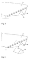
- Fig. 2 shows the rear, d. H. the rotor facing away from the engine room 3.
- a recess 12 is provided in the lower in Fig. 2, d. H. the sea surface facing side of the lining of the machine house 3, a recess 12 is provided.
- the recess 12 receives the retracted rescue capsule 11 in a form-fitting manner.
- the retracted rescue capsule 11 is integrated into the outer design of the machine house and thus offers an aesthetically pleasing sight.
- Fig. 3 the beginning of the descent of the rescue capsule 11 in Fig. 2 is shown.
- the rescue capsule 11 is slightly detached from the recess 12 of the lining of the machine house 3.
- the rescue capsule 11 is triangular in cross-section.
- the escape capsule 11 released from the recess 12 is shown in its overall tent-shaped shape.
- a roller 14 from which the rope rolls, arranged.
- a (not shown) brake is provided on the roller 14 .
- the pulley may also be fastened inside the rescue capsule 11 or on the machine housing 3
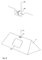
- the escape capsule 11 shown in FIG. 5 has a capsule door 16 in a roof wall.
- the service personnel accesses through an exit opening provided in the recess 12 and opens the capsule door 11.
- the service personnel can get into the rescue capsule 11, then close the capsule door 16 from the inside and drive protected from the weather after rappelling on the sea surface , Exit opening and capsule door in case of danger, a direct connection between the interior of the machine house and the interior of the rescue capsule 11.
- the rescue capsule 11 in Fig. 5 is shown during rappelling.
- FIG. 6 shows the rescue capsule 11 in a form integrated in the spinner of the rotor 6.
- the service personnel who are e.g. stops for maintenance in the rotor hub 17, climb into the spinner to get into the escape pod 11.
- a rescue capsule 11 is shown, which is arranged in the normal position below the machine house 3. Below the machine house 3, a rail profile 18 is provided, on which the rescue capsule 11 hangs in the normal position.
- the area of the rescue capsule 11 facing the machine house 3 is flattened.
- the capsule door is provided in the flattened area. The service personnel can enter the escape pod 11 through the capsule door from the machine house 3. Thereafter, the escape pod 11 is roped off.
Landscapes
- Engineering & Computer Science (AREA)
- Life Sciences & Earth Sciences (AREA)
- Sustainable Development (AREA)
- Sustainable Energy (AREA)
- Chemical & Material Sciences (AREA)
- Combustion & Propulsion (AREA)
- Mechanical Engineering (AREA)
- General Engineering & Computer Science (AREA)
- Emergency Lowering Means (AREA)
- Wind Motors (AREA)
Applications Claiming Priority (1)
| Application Number | Priority Date | Filing Date | Title |
|---|---|---|---|
| DE102004037458.9A DE102004037458B4 (de) | 2004-08-02 | 2004-08-02 | Rettungskapsel für Windenergieanlagen |
Publications (3)
| Publication Number | Publication Date |
|---|---|
| EP1624186A2 true EP1624186A2 (fr) | 2006-02-08 |
| EP1624186A3 EP1624186A3 (fr) | 2011-09-07 |
| EP1624186B1 EP1624186B1 (fr) | 2015-02-25 |
Family
ID=35058570
Family Applications (1)
| Application Number | Title | Priority Date | Filing Date |
|---|---|---|---|
| EP05015960.7A Expired - Lifetime EP1624186B1 (fr) | 2004-08-02 | 2005-07-22 | Capsule de sauvetage pour des installations d'énergie éolienne |
Country Status (4)
| Country | Link |
|---|---|
| EP (1) | EP1624186B1 (fr) |
| DE (1) | DE102004037458B4 (fr) |
| DK (1) | DK1624186T3 (fr) |
| ES (1) | ES2537103T3 (fr) |
Cited By (7)
| Publication number | Priority date | Publication date | Assignee | Title |
|---|---|---|---|---|
| CN103183116A (zh) * | 2011-12-31 | 2013-07-03 | 华锐风电科技(集团)股份有限公司 | 逃生装置及海上风电机组 |
| WO2012160038A3 (fr) * | 2011-05-25 | 2013-07-25 | Uwe Bergmann | Procédé et dispositif de sauvetage |
| WO2013174678A1 (fr) * | 2012-05-21 | 2013-11-28 | Uwe Bergmann | Procédé de sauvetage et dispositif de sauvetage |
| WO2015078480A1 (fr) | 2013-11-29 | 2015-06-04 | Ha-Pa Holding A/S | Système de secours |
| CN108969918A (zh) * | 2018-08-31 | 2018-12-11 | 北京金风科创风电设备有限公司 | 用于风力发电机组的逃生设备及风力发电机组 |
| EP3492145A1 (fr) * | 2017-11-30 | 2019-06-05 | Senvion GmbH | Système de sauvetage des personnes et procédé d'évacuation des personnes d'un bâtiment |
| DE102017011084A1 (de) | 2017-11-30 | 2019-06-06 | Senvion Gmbh | Windenergieanlage mit einem System zum vertikalen Transport von Personen und/oder Material |
Families Citing this family (7)
| Publication number | Priority date | Publication date | Assignee | Title |
|---|---|---|---|---|
| DE102006034299A1 (de) * | 2006-07-21 | 2008-01-24 | Daubner & Stommel GbR Bau-Werk-Planung (vertretungsberechtigter Gesellschafter: Matthias Stommel, 27777 Ganderkesee) | Windenergieanlage und Verfahren zum Betreiben der Windenergieanlage |
| DE202010002467U1 (de) * | 2010-02-17 | 2011-06-22 | Bergmann, Dirk, 32139 | Rettungsvorrichtung |
| DE202010008582U1 (de) * | 2010-09-20 | 2011-12-27 | Dirk Bergmann | Rettungs-Abseilvorrichtung |
| ES2671048B1 (es) * | 2016-12-02 | 2019-04-02 | Adwen Offshore S L | Equipo de seguridad y control para asegurar el descenso de material u operarios para un aerogenerador, y aerogenerador que comprende el equipo |
| ES2966624T3 (es) * | 2017-11-03 | 2024-04-23 | Vestas Wind Sys As | Método para realizar mantenimiento en una parte de turbina eólica |
| EP3795823A1 (fr) * | 2019-06-28 | 2021-03-24 | Ørsted Wind Power A/S | Monopile et structure d'éolienne |
| CN113153647B (zh) * | 2021-05-10 | 2022-08-05 | 浙江运达风电股份有限公司 | 一种预装底平台的底层塔筒及其安装方法 |
Citations (5)
| Publication number | Priority date | Publication date | Assignee | Title |
|---|---|---|---|---|
| DE2500975A1 (de) | 1974-01-22 | 1975-07-24 | Brown & Ass James G | Meeresplattform |
| DE4205946A1 (de) | 1992-02-24 | 1993-08-26 | Howaldtswerke Deutsche Werft | Rettungsgeraet fuer plattformen |
| DE20202214U1 (de) | 2002-02-14 | 2002-06-06 | Krischke, Mathias, 65195 Wiesbaden | Schwimmfähige Rettungsvorrichtung |
| WO2003069155A1 (fr) | 2002-02-16 | 2003-08-21 | Aloys Wobben | Parc a eoliennes en mer |
| DE10222472A1 (de) | 2002-05-22 | 2003-12-11 | Klaus Flores | Verfahren und Vorrichtung zur Höhenpositionierung |
Family Cites Families (9)
| Publication number | Priority date | Publication date | Assignee | Title |
|---|---|---|---|---|
| DE2100565A1 (de) * | 1971-01-07 | 1972-07-20 | Leßmann, Alfons, 4780 Lippstadt, Stahl, Helmut, 8622 Burgkunstadt | Sportgerat, insbesondere Wasser sportgerat |
| DE2412673C2 (de) * | 1974-03-16 | 1985-06-05 | Rolf Albert Artur 2000 Hamburg Schmidt | Gleitboot |
| NL7509084A (en) * | 1975-07-30 | 1977-02-01 | Mij Tot Verwerving En Exploita | Launching rescue craft from drilling platform - by readying and manning craft on movable support, lowering support, and floating craft |
| DE3224139A1 (de) * | 1982-06-29 | 1983-12-29 | Erno Raumfahrttechnik Gmbh, 2800 Bremen | Rettungsvorrichtung |
| PL145297B1 (en) * | 1984-09-05 | 1988-08-31 | Politechnika Gdanska | Free-thrown immersible rescue apparatus for waterborne facilities operating under severe weather conditions |
| US5127491A (en) * | 1991-02-05 | 1992-07-07 | Just Buddy Hayaldree P | Terra firma exterior-mount fire/rescue elevator |
| GB2268711B (en) * | 1992-07-13 | 1996-07-17 | Laing & Sons Ltd James | Suspended staging |
| DE50008902D1 (de) * | 2000-03-17 | 2005-01-13 | Gen Electric | Offshore-Windkraftanlage |
| US20030057023A1 (en) * | 2001-09-25 | 2003-03-27 | Capewell Components Company, Llc | Compact descent controller |
-
2004
- 2004-08-02 DE DE102004037458.9A patent/DE102004037458B4/de not_active Expired - Fee Related
-
2005
- 2005-07-22 ES ES05015960.7T patent/ES2537103T3/es not_active Expired - Lifetime
- 2005-07-22 EP EP05015960.7A patent/EP1624186B1/fr not_active Expired - Lifetime
- 2005-07-22 DK DK05015960.7T patent/DK1624186T3/en active
Patent Citations (5)
| Publication number | Priority date | Publication date | Assignee | Title |
|---|---|---|---|---|
| DE2500975A1 (de) | 1974-01-22 | 1975-07-24 | Brown & Ass James G | Meeresplattform |
| DE4205946A1 (de) | 1992-02-24 | 1993-08-26 | Howaldtswerke Deutsche Werft | Rettungsgeraet fuer plattformen |
| DE20202214U1 (de) | 2002-02-14 | 2002-06-06 | Krischke, Mathias, 65195 Wiesbaden | Schwimmfähige Rettungsvorrichtung |
| WO2003069155A1 (fr) | 2002-02-16 | 2003-08-21 | Aloys Wobben | Parc a eoliennes en mer |
| DE10222472A1 (de) | 2002-05-22 | 2003-12-11 | Klaus Flores | Verfahren und Vorrichtung zur Höhenpositionierung |
Cited By (9)
| Publication number | Priority date | Publication date | Assignee | Title |
|---|---|---|---|---|
| WO2012160038A3 (fr) * | 2011-05-25 | 2013-07-25 | Uwe Bergmann | Procédé et dispositif de sauvetage |
| CN103547318A (zh) * | 2011-05-25 | 2014-01-29 | 乌维·贝格曼 | 救援方法以及救援装置 |
| CN103183116A (zh) * | 2011-12-31 | 2013-07-03 | 华锐风电科技(集团)股份有限公司 | 逃生装置及海上风电机组 |
| WO2013174678A1 (fr) * | 2012-05-21 | 2013-11-28 | Uwe Bergmann | Procédé de sauvetage et dispositif de sauvetage |
| WO2015078480A1 (fr) | 2013-11-29 | 2015-06-04 | Ha-Pa Holding A/S | Système de secours |
| EP3492145A1 (fr) * | 2017-11-30 | 2019-06-05 | Senvion GmbH | Système de sauvetage des personnes et procédé d'évacuation des personnes d'un bâtiment |
| DE102017011083A1 (de) | 2017-11-30 | 2019-06-06 | Senvion Gmbh | Personenrettungssystem und Verfahren zur Evakuierung von Personen aus einem Bauwerk |
| DE102017011084A1 (de) | 2017-11-30 | 2019-06-06 | Senvion Gmbh | Windenergieanlage mit einem System zum vertikalen Transport von Personen und/oder Material |
| CN108969918A (zh) * | 2018-08-31 | 2018-12-11 | 北京金风科创风电设备有限公司 | 用于风力发电机组的逃生设备及风力发电机组 |
Also Published As
| Publication number | Publication date |
|---|---|
| DK1624186T3 (en) | 2015-05-26 |
| ES2537103T3 (es) | 2015-06-02 |
| DE102004037458B4 (de) | 2021-01-14 |
| DE102004037458A1 (de) | 2006-02-23 |
| EP1624186A3 (fr) | 2011-09-07 |
| EP1624186B1 (fr) | 2015-02-25 |
Similar Documents
| Publication | Publication Date | Title |
|---|---|---|
| DE102011050630B4 (de) | Rettungsverfahren und Rettungsvorrichtung | |
| EP1624186B1 (fr) | Capsule de sauvetage pour des installations d'énergie éolienne | |
| US10435274B2 (en) | Seaworthy, watertight, floatable container for an offshore wind turbine maintenance program | |
| EP1478851B1 (fr) | Parc a eoliennes en mer | |
| EP1328429B1 (fr) | Parc eolien | |
| EP2552549B1 (fr) | Dispositif de descente à câble | |
| EP2438294B1 (fr) | Procédé et dispositif d'installation d'une centrale marémotrice | |
| EP3253927B1 (fr) | Structure de fondation en mer pourvue d'une galerie et d'un système d'accostage amélioré | |
| WO2013174678A1 (fr) | Procédé de sauvetage et dispositif de sauvetage | |
| DE202012100556U1 (de) | Koppelelement, Aussetzvorrichtung sowie Boot | |
| DE2424648C3 (de) | Rettungsgerät für Schiffe | |
| DE102004033681A1 (de) | Windenergieanlage mit einem Turm | |
| EP3492145B1 (fr) | Système de sauvetage des personnes et procédé d'évacuation des personnes d'un bâtiment | |
| DE202010002467U1 (de) | Rettungsvorrichtung | |
| WO2004076853A1 (fr) | Eolienne en mer | |
| DE1984936U (de) | Schwimmende seestation. | |
| EP1389581A1 (fr) | Méthode et appareil pour l'approvisionnement et l'entretien des constructions en mer | |
| DE102014016269A1 (de) | "Wasserfahrzeug aus Oberteil mit Unterteil, und mit Anlagen aus Windkraft, und Wasserspeicher." | |
| CN216722705U (zh) | 一种无人零碳排放养殖网箱 | |
| EP1565619A2 (fr) | Dispositif pour amarrer un bateau a un batiment maritime | |
| EP2852441A1 (fr) | Procédé de sauvetage et dispositif de sauvetage | |
| DE102009042793A1 (de) | Verfahren zum sicheren Personenüberstieg und zur Materialübergabe von einem Versorgungsschiff auf eine stationäre Struktur im Wasser, z.B. eine Offshore-Windenergieanlage | |
| EP3492737A1 (fr) | Éolienne doté d'un système de transport vertical des personnes et / ou des matériaux | |
| DE202014000460U1 (de) | Komposit-Rettungsinsel zur Evakuierung, Sicherung und Rettung von schiffbrüchigen Personen |
Legal Events
| Date | Code | Title | Description |
|---|---|---|---|
| PUAI | Public reference made under article 153(3) epc to a published international application that has entered the european phase |
Free format text: ORIGINAL CODE: 0009012 |
|
| AK | Designated contracting states |
Kind code of ref document: A2 Designated state(s): AT BE BG CH CY CZ DE DK EE ES FI FR GB GR HU IE IS IT LI LT LU LV MC NL PL PT RO SE SI SK TR |
|
| AX | Request for extension of the european patent |
Extension state: AL BA HR MK YU |
|
| PUAL | Search report despatched |
Free format text: ORIGINAL CODE: 0009013 |
|
| AK | Designated contracting states |
Kind code of ref document: A3 Designated state(s): AT BE BG CH CY CZ DE DK EE ES FI FR GB GR HU IE IS IT LI LT LU LV MC NL PL PT RO SE SI SK TR |
|
| AX | Request for extension of the european patent |
Extension state: AL BA HR MK YU |
|
| RIC1 | Information provided on ipc code assigned before grant |
Ipc: F03D 11/00 20060101AFI20110803BHEP Ipc: F03D 1/00 20060101ALI20110803BHEP |
|
| 17P | Request for examination filed |
Effective date: 20120206 |
|
| AKX | Designation fees paid |
Designated state(s): AT BE BG CH CY CZ DE DK EE ES FI FR GB GR HU IE IS IT LI LT LU LV MC NL PL PT RO SE SI SK TR |
|
| 17Q | First examination report despatched |
Effective date: 20120502 |
|
| GRAP | Despatch of communication of intention to grant a patent |
Free format text: ORIGINAL CODE: EPIDOSNIGR1 |
|
| INTG | Intention to grant announced |
Effective date: 20140509 |
|
| RAP1 | Party data changed (applicant data changed or rights of an application transferred) |
Owner name: REPOWER SYSTEMS SE |
|
| RAP1 | Party data changed (applicant data changed or rights of an application transferred) |
Owner name: SENVION SE |
|
| GRAS | Grant fee paid |
Free format text: ORIGINAL CODE: EPIDOSNIGR3 |
|
| GRAP | Despatch of communication of intention to grant a patent |
Free format text: ORIGINAL CODE: EPIDOSNIGR1 |
|
| INTG | Intention to grant announced |
Effective date: 20141003 |
|
| RAP1 | Party data changed (applicant data changed or rights of an application transferred) |
Owner name: SENVION SE |
|
| GRAA | (expected) grant |
Free format text: ORIGINAL CODE: 0009210 |
|
| AK | Designated contracting states |
Kind code of ref document: B1 Designated state(s): AT BE BG CH CY CZ DE DK EE ES FI FR GB GR HU IE IS IT LI LT LU LV MC NL PL PT RO SE SI SK TR |
|
| REG | Reference to a national code |
Ref country code: GB Ref legal event code: FG4D Free format text: NOT ENGLISH |
|
| REG | Reference to a national code |
Ref country code: CH Ref legal event code: EP |
|
| REG | Reference to a national code |
Ref country code: DE Ref legal event code: R081 Ref document number: 502005014689 Country of ref document: DE Owner name: SENVION GMBH, DE Free format text: FORMER OWNER: REPOWER SYSTEMS AG, 22297 HAMBURG, DE |
|
| REG | Reference to a national code |
Ref country code: IE Ref legal event code: FG4D Free format text: LANGUAGE OF EP DOCUMENT: GERMAN |
|
| REG | Reference to a national code |
Ref country code: DE Ref legal event code: R096 Ref document number: 502005014689 Country of ref document: DE Effective date: 20150409 |
|
| REG | Reference to a national code |
Ref country code: AT Ref legal event code: REF Ref document number: 712232 Country of ref document: AT Kind code of ref document: T Effective date: 20150415 |
|
| REG | Reference to a national code |
Ref country code: DK Ref legal event code: T3 Effective date: 20150522 |
|
| REG | Reference to a national code |
Ref country code: ES Ref legal event code: FG2A Ref document number: 2537103 Country of ref document: ES Kind code of ref document: T3 Effective date: 20150602 |
|
| REG | Reference to a national code |
Ref country code: NL Ref legal event code: VDEP Effective date: 20150225 |
|
| REG | Reference to a national code |
Ref country code: LT Ref legal event code: MG4D |
|
| PG25 | Lapsed in a contracting state [announced via postgrant information from national office to epo] |
Ref country code: LT Free format text: LAPSE BECAUSE OF FAILURE TO SUBMIT A TRANSLATION OF THE DESCRIPTION OR TO PAY THE FEE WITHIN THE PRESCRIBED TIME-LIMIT Effective date: 20150225 Ref country code: FI Free format text: LAPSE BECAUSE OF FAILURE TO SUBMIT A TRANSLATION OF THE DESCRIPTION OR TO PAY THE FEE WITHIN THE PRESCRIBED TIME-LIMIT Effective date: 20150225 Ref country code: SE Free format text: LAPSE BECAUSE OF FAILURE TO SUBMIT A TRANSLATION OF THE DESCRIPTION OR TO PAY THE FEE WITHIN THE PRESCRIBED TIME-LIMIT Effective date: 20150225 |
|
| REG | Reference to a national code |
Ref country code: DE Ref legal event code: R082 Ref document number: 502005014689 Country of ref document: DE Representative=s name: GROTH, WIELAND, DR., DE Ref country code: DE Ref legal event code: R081 Ref document number: 502005014689 Country of ref document: DE Owner name: SENVION GMBH, DE Free format text: FORMER OWNER: SENVION SE, 22297 HAMBURG, DE |
|
| PG25 | Lapsed in a contracting state [announced via postgrant information from national office to epo] |
Ref country code: GR Free format text: LAPSE BECAUSE OF FAILURE TO SUBMIT A TRANSLATION OF THE DESCRIPTION OR TO PAY THE FEE WITHIN THE PRESCRIBED TIME-LIMIT Effective date: 20150526 Ref country code: IS Free format text: LAPSE BECAUSE OF FAILURE TO SUBMIT A TRANSLATION OF THE DESCRIPTION OR TO PAY THE FEE WITHIN THE PRESCRIBED TIME-LIMIT Effective date: 20150625 Ref country code: LV Free format text: LAPSE BECAUSE OF FAILURE TO SUBMIT A TRANSLATION OF THE DESCRIPTION OR TO PAY THE FEE WITHIN THE PRESCRIBED TIME-LIMIT Effective date: 20150225 |
|
| RAP2 | Party data changed (patent owner data changed or rights of a patent transferred) |
Owner name: SENVION GMBH |
|
| PG25 | Lapsed in a contracting state [announced via postgrant information from national office to epo] |
Ref country code: NL Free format text: LAPSE BECAUSE OF FAILURE TO SUBMIT A TRANSLATION OF THE DESCRIPTION OR TO PAY THE FEE WITHIN THE PRESCRIBED TIME-LIMIT Effective date: 20150225 |
|
| PG25 | Lapsed in a contracting state [announced via postgrant information from national office to epo] |
Ref country code: SK Free format text: LAPSE BECAUSE OF FAILURE TO SUBMIT A TRANSLATION OF THE DESCRIPTION OR TO PAY THE FEE WITHIN THE PRESCRIBED TIME-LIMIT Effective date: 20150225 Ref country code: RO Free format text: LAPSE BECAUSE OF FAILURE TO SUBMIT A TRANSLATION OF THE DESCRIPTION OR TO PAY THE FEE WITHIN THE PRESCRIBED TIME-LIMIT Effective date: 20150225 Ref country code: CZ Free format text: LAPSE BECAUSE OF FAILURE TO SUBMIT A TRANSLATION OF THE DESCRIPTION OR TO PAY THE FEE WITHIN THE PRESCRIBED TIME-LIMIT Effective date: 20150225 Ref country code: EE Free format text: LAPSE BECAUSE OF FAILURE TO SUBMIT A TRANSLATION OF THE DESCRIPTION OR TO PAY THE FEE WITHIN THE PRESCRIBED TIME-LIMIT Effective date: 20150225 |
|
| REG | Reference to a national code |
Ref country code: AT Ref legal event code: HC Ref document number: 712232 Country of ref document: AT Kind code of ref document: T Owner name: SENVION GMBH, DE Effective date: 20150921 |
|
| REG | Reference to a national code |
Ref country code: DE Ref legal event code: R097 Ref document number: 502005014689 Country of ref document: DE |
|
| PG25 | Lapsed in a contracting state [announced via postgrant information from national office to epo] |
Ref country code: PL Free format text: LAPSE BECAUSE OF FAILURE TO SUBMIT A TRANSLATION OF THE DESCRIPTION OR TO PAY THE FEE WITHIN THE PRESCRIBED TIME-LIMIT Effective date: 20150225 |
|
| PG25 | Lapsed in a contracting state [announced via postgrant information from national office to epo] |
Ref country code: IT Free format text: LAPSE BECAUSE OF FAILURE TO SUBMIT A TRANSLATION OF THE DESCRIPTION OR TO PAY THE FEE WITHIN THE PRESCRIBED TIME-LIMIT Effective date: 20150225 |
|
| PLBE | No opposition filed within time limit |
Free format text: ORIGINAL CODE: 0009261 |
|
| STAA | Information on the status of an ep patent application or granted ep patent |
Free format text: STATUS: NO OPPOSITION FILED WITHIN TIME LIMIT |
|
| 26N | No opposition filed |
Effective date: 20151126 |
|
| PG25 | Lapsed in a contracting state [announced via postgrant information from national office to epo] |
Ref country code: SI Free format text: LAPSE BECAUSE OF FAILURE TO SUBMIT A TRANSLATION OF THE DESCRIPTION OR TO PAY THE FEE WITHIN THE PRESCRIBED TIME-LIMIT Effective date: 20150225 Ref country code: MC Free format text: LAPSE BECAUSE OF FAILURE TO SUBMIT A TRANSLATION OF THE DESCRIPTION OR TO PAY THE FEE WITHIN THE PRESCRIBED TIME-LIMIT Effective date: 20150225 |
|
| REG | Reference to a national code |
Ref country code: CH Ref legal event code: PL |
|
| PG25 | Lapsed in a contracting state [announced via postgrant information from national office to epo] |
Ref country code: LU Free format text: LAPSE BECAUSE OF FAILURE TO SUBMIT A TRANSLATION OF THE DESCRIPTION OR TO PAY THE FEE WITHIN THE PRESCRIBED TIME-LIMIT Effective date: 20150722 |
|
| REG | Reference to a national code |
Ref country code: IE Ref legal event code: MM4A |
|
| PG25 | Lapsed in a contracting state [announced via postgrant information from national office to epo] |
Ref country code: LI Free format text: LAPSE BECAUSE OF NON-PAYMENT OF DUE FEES Effective date: 20150731 Ref country code: CH Free format text: LAPSE BECAUSE OF NON-PAYMENT OF DUE FEES Effective date: 20150731 |
|
| REG | Reference to a national code |
Ref country code: FR Ref legal event code: PLFP Year of fee payment: 12 |
|
| PG25 | Lapsed in a contracting state [announced via postgrant information from national office to epo] |
Ref country code: IE Free format text: LAPSE BECAUSE OF NON-PAYMENT OF DUE FEES Effective date: 20150722 |
|
| REG | Reference to a national code |
Ref country code: AT Ref legal event code: MM01 Ref document number: 712232 Country of ref document: AT Kind code of ref document: T Effective date: 20150722 |
|
| PG25 | Lapsed in a contracting state [announced via postgrant information from national office to epo] |
Ref country code: AT Free format text: LAPSE BECAUSE OF NON-PAYMENT OF DUE FEES Effective date: 20150722 |
|
| PG25 | Lapsed in a contracting state [announced via postgrant information from national office to epo] |
Ref country code: BG Free format text: LAPSE BECAUSE OF FAILURE TO SUBMIT A TRANSLATION OF THE DESCRIPTION OR TO PAY THE FEE WITHIN THE PRESCRIBED TIME-LIMIT Effective date: 20150225 Ref country code: HU Free format text: LAPSE BECAUSE OF FAILURE TO SUBMIT A TRANSLATION OF THE DESCRIPTION OR TO PAY THE FEE WITHIN THE PRESCRIBED TIME-LIMIT; INVALID AB INITIO Effective date: 20050722 |
|
| PG25 | Lapsed in a contracting state [announced via postgrant information from national office to epo] |
Ref country code: CY Free format text: LAPSE BECAUSE OF FAILURE TO SUBMIT A TRANSLATION OF THE DESCRIPTION OR TO PAY THE FEE WITHIN THE PRESCRIBED TIME-LIMIT Effective date: 20150225 |
|
| REG | Reference to a national code |
Ref country code: FR Ref legal event code: PLFP Year of fee payment: 13 |
|
| PG25 | Lapsed in a contracting state [announced via postgrant information from national office to epo] |
Ref country code: BE Free format text: LAPSE BECAUSE OF NON-PAYMENT OF DUE FEES Effective date: 20150731 |
|
| PG25 | Lapsed in a contracting state [announced via postgrant information from national office to epo] |
Ref country code: TR Free format text: LAPSE BECAUSE OF FAILURE TO SUBMIT A TRANSLATION OF THE DESCRIPTION OR TO PAY THE FEE WITHIN THE PRESCRIBED TIME-LIMIT Effective date: 20150225 |
|
| PG25 | Lapsed in a contracting state [announced via postgrant information from national office to epo] |
Ref country code: PT Free format text: LAPSE BECAUSE OF FAILURE TO SUBMIT A TRANSLATION OF THE DESCRIPTION OR TO PAY THE FEE WITHIN THE PRESCRIBED TIME-LIMIT Effective date: 20150225 |
|
| REG | Reference to a national code |
Ref country code: FR Ref legal event code: PLFP Year of fee payment: 14 |
|
| PGFP | Annual fee paid to national office [announced via postgrant information from national office to epo] |
Ref country code: GB Payment date: 20200724 Year of fee payment: 16 Ref country code: DE Payment date: 20200723 Year of fee payment: 16 Ref country code: ES Payment date: 20200818 Year of fee payment: 16 Ref country code: FR Payment date: 20200727 Year of fee payment: 16 Ref country code: DK Payment date: 20200722 Year of fee payment: 16 |
|
| REG | Reference to a national code |
Ref country code: DE Ref legal event code: R119 Ref document number: 502005014689 Country of ref document: DE |
|
| REG | Reference to a national code |
Ref country code: DK Ref legal event code: EBP Effective date: 20210731 |
|
| GBPC | Gb: european patent ceased through non-payment of renewal fee |
Effective date: 20210722 |
|
| PG25 | Lapsed in a contracting state [announced via postgrant information from national office to epo] |
Ref country code: GB Free format text: LAPSE BECAUSE OF NON-PAYMENT OF DUE FEES Effective date: 20210722 Ref country code: DE Free format text: LAPSE BECAUSE OF NON-PAYMENT OF DUE FEES Effective date: 20220201 |
|
| PG25 | Lapsed in a contracting state [announced via postgrant information from national office to epo] |
Ref country code: FR Free format text: LAPSE BECAUSE OF NON-PAYMENT OF DUE FEES Effective date: 20210731 |
|
| PG25 | Lapsed in a contracting state [announced via postgrant information from national office to epo] |
Ref country code: DK Free format text: LAPSE BECAUSE OF NON-PAYMENT OF DUE FEES Effective date: 20210731 |
|
| REG | Reference to a national code |
Ref country code: ES Ref legal event code: FD2A Effective date: 20220901 |
|
| PG25 | Lapsed in a contracting state [announced via postgrant information from national office to epo] |
Ref country code: ES Free format text: LAPSE BECAUSE OF NON-PAYMENT OF DUE FEES Effective date: 20210723 |