EP1624548A2 - Ausgangsklemmenanordnung für einen Fahrzeuggenerator - Google Patents
Ausgangsklemmenanordnung für einen Fahrzeuggenerator Download PDFInfo
- Publication number
- EP1624548A2 EP1624548A2 EP04021483A EP04021483A EP1624548A2 EP 1624548 A2 EP1624548 A2 EP 1624548A2 EP 04021483 A EP04021483 A EP 04021483A EP 04021483 A EP04021483 A EP 04021483A EP 1624548 A2 EP1624548 A2 EP 1624548A2
- Authority
- EP
- European Patent Office
- Prior art keywords
- output terminal
- direction output
- axial direction
- rear bracket
- assembly
- Prior art date
- Legal status (The legal status is an assumption and is not a legal conclusion. Google has not performed a legal analysis and makes no representation as to the accuracy of the status listed.)
- Withdrawn
Links
Images


Classifications
-
- H—ELECTRICITY
- H02—GENERATION; CONVERSION OR DISTRIBUTION OF ELECTRIC POWER
- H02K—DYNAMO-ELECTRIC MACHINES
- H02K5/00—Casings; Enclosures; Supports
- H02K5/04—Casings or enclosures characterised by the shape, form or construction thereof
- H02K5/22—Auxiliary parts of casings not covered by groups H02K5/06-H02K5/20, e.g. shaped to form connection boxes or terminal boxes
- H02K5/225—Terminal boxes or connection arrangements
-
- H—ELECTRICITY
- H02—GENERATION; CONVERSION OR DISTRIBUTION OF ELECTRIC POWER
- H02K—DYNAMO-ELECTRIC MACHINES
- H02K15/00—Processes or apparatus specially adapted for manufacturing, assembling, maintaining or repairing of dynamo-electric machines
- H02K15/14—Casings; Enclosures; Supports
-
- H—ELECTRICITY
- H02—GENERATION; CONVERSION OR DISTRIBUTION OF ELECTRIC POWER
- H02K—DYNAMO-ELECTRIC MACHINES
- H02K3/00—Details of windings
- H02K3/32—Windings characterised by the shape, form or construction of the insulation
- H02K3/34—Windings characterised by the shape, form or construction of the insulation between conductors or between conductor and core, e.g. slot insulation
Definitions
- the present invention relates to an output terminal assembly of an alternator for a vehicle, and in particular to an improved output terminal assembly of an alternator for a vehicle capable of increasing of a contact area in order that a current density per unit area may be decreased and preventing a damage of a sealing member and decreasing an error during a fabrication by improving an assembling performance in such a manner that a contact structure between an axial direction output terminal and a radial direction output terminal is improved.
- a vehicle alternator includes a casing 30 that is formed of a rear bracket 10 having a shaft support part 11 and a front bracket 20, a shaft 60 that is installed in the interior of the casing wherein a pulley 40 is fixed to one end of the shaft 60, a rotor 70 fixed to the shaft, a fan 71 fixed to both sides of the rotor, a stator 50 fixed to an inner wall surface of the casing, a slip ring 52 that is fixed to the other end of the shaft for supplying current to the rotor, a pair of brushes 81 that contact with the slip ring, a brush assembly 80 that receives the brush, a rectifier assembly 90 that is electrically connected with the stator, a heat sink 91 that is engaged to the brush assembly, and a regulator 92 that is connected with the heat sink for adjusting the size of an alternating current voltage generated by the stator.
- an output terminal 100 in order to output the current generated based on the rotor 70 and the stator 50 to the outside.
- the output terminal 100 is formed of an axial direction output terminal 110, and a radius direction output terminal 120 connected from an outer portion of the same.
- the axial direction output terminal 110 includes a bolt head-shaped head part 111 and an extension part 112, a body part 113, and a thread part 115 formed at an end of the same.
- the radius direction output terminal 120 includes an assembling hole 123 inserted onto the thread part 115, an exposure part 121 formed in the opposite portion of the same, and an insulation mold 122 that surrounds the above elements.
- the thread part 115 of the axial direction output terminal 110 sequentially passes through a plate 94, a circuit board 93, an insulation pipe 95, and a heat sink 91 in an inner side of the bracket 10 and is exposed to the outside of the bracket 10.
- the assembling hole 123 of the radius direction output terminal 120 surrounded by the insulation mold 122 is inserted onto the thread part 115 and is engaged using a nut 116.
- the thread part 115 of the end of the same has less diameter as compared to the extension part 112 and the head part 111. Therefore, the contacting area is small when being assembled with the radius direction output terminal 120.
- the axial direction output terminal 110 for a desired contact between the terminal of the circuit board and the heat sink 91 may be inwardly pushed in the inner space of the bracket 10 by an assembling force, therefore a certain error may occur in the contact.
- an alternator that includes a casing formed of a rear bracket and a front bracket, a rotor fixed to the shaft in the interior of the casing, a stator fixed to an inner wall surface of the casing, a brush assembly, a rectifier assembly, a heat sink and a regulator
- an output terminal assembly of an alternator for a vehicle comprising an output terminal that includes an axial direction terminal engaged to the heat sink provided in an inner side of the rear bracket for outputting power to the outside, and a radius direction output terminal
- the axial direction output terminal includes a head part, an extension part, a body part, and a thread part formed at one end
- the radius direction output terminal includes an exposure part of an outer side end, an assembling hole formed at an inner end, and an insulation mold that covers the above elements; and wherein the extension part of the axial direction output terminal is inserted into an assembling hole of the radius direction output terminal, and the thread part of the axial direction output terminal is inserted from the outer side of the
- an alternator that includes a casing formed of a rear bracket and a front bracket, a rotor fixed to the shaft in the interior of the casing, a stator fixed to an inner wall surface of the casing, a brush assembly, a rectifier assembly, a heat sink and a regulator
- an output terminal assembly of an alternator for a vehicle comprising an output terminal that includes an axial direction terminal engaged to the heat sink provided in an inner side of the rear bracket for outputting power to the outside, and a radius direction output terminal, wherein the axial direction output terminal includes a head part, an extension part, a body part, and a thread part at one end, and the radius direction output terminal includes an exposure part at an outer end, and an assembling hole substantially larger for inserting the extension part; and wherein a body part of the radius direction output terminal and the head part of the axial direction output terminal are covered by an insulation mold in a state that the extension part of the axial direction terminal is inserted into the assembling hole of the radius direction
- Figure 3 is a disassembled cross sectional view illustrating an output terminal assembly according to an embodiment of the present invention
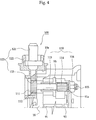
- Figure 4 is a cross sectional view illustrating an assembled state of an output terminal assembly according to the present invention.
- the alternator includes a casing 30 formed of a rear bracket 10 and a front bracket 20, a rotor 70 fixed to a shaft 60 in the interior of the casing, a stator 50 fixed to an inner wall surface of the casing, a brush assembly 80, a rectifier assembly 90, a heat sink 91, and a regulator 92.
- the output terminal 100 engaged with the heat 91 provided in the inner side of the rear bracket 10 for outputting power to the outside includes an axial direction output terminal 110, and a radius direction output terminal 120.
- the axial direction output terminal 110 includes a head part 111, an extension part 112, a body part 113, and a thread part 115 formed at one end of the same.
- the radius direction output terminal 120 includes an exposure part 121, an assembling hole 123 provided in the inner side of the exposure part 121 and formed in a large size for thereby inserting the extension part 112, and an insulation mold 112 that surrounds the above elements.
- the extension part 112 of the axial direction output terminal 110 is inserted into the assembling hole 123 of the radius direction output terminal 120, and the thread part 115 of the axial direction output terminal 110 is inserted from the outer side of the rear bracket 10 to the inner direction of the rear bracket 10 for thereby being fixed by a nut 116.
- the axial direction output terminal 110 includes the extension part 112 of the lower side of the head part, and a body part 113.
- the axial direction output terminal 110 further includes a heat sink contact part 114 at an intermediate portion.
- the diameter D1 of the extension part 112 and the diameter D2 of the heat sink contact part 114 are D2/D1 ⁇ 0.70.
- the diameter of the extension part 112 is larger than the diameter of the heat sink contact part 114.
- the rear bracket 10 has an assembling guide surface 10a in one side, and the exposure part 121 of the radius direction output terminal 120 contacts with the assembling guide surface 10a.
- the insulation mold 122 could be implemented in another method.
- the output terminal 100 includes an axial direction output terminal 110 engaged with a heat sink 91 provided in the inner side of the rear bracket 10 for outputting power to the outside, and a radius direction output terminal 120.
- the axial direction output terminal 110 includes a head part 111, an extension part 112, a body part 113, and a thread part 115 formed at one end.
- the radius direction output terminal 120 includes an exposure part 121 of an outer end, and an assembling hole 123 that is formed at an inner end of the opposite side for thereby inserting the extension part 112 thereinto.
- the insulation mold 122 surrounds the body part of the radius direction output terminal 120 and the head part 111 of the axial direction output terminal 110.
- the thread part 115 of the axial direction output terminal 110 is inserted from the outer side of the rear bracket 10 to the inner side of the rear bracket 10 for thereby being fixed using a nut 116.
- the axial direction output terminal 110 is inserted from the outer side of the rear bracket 10 to the inner direction of the rear bracket 10, the assembling of the output terminal is finished before the rear bracket 10 is assembled to the alternator.
- the head part of the axial direction output terminal is provided outside the rear bracket, it is possible to increase the contact area with respect to the radius direction output terminal without making the terminal hole of the heat sink larger.
- the radius direction output terminal is assembled with the axial direction output terminal before they are assembled with the bracket. Therefore, it is possible to assembly without a tight insertion, so that the insulation mold is not damaged.
- the radius direction output terminal When assembling the radius direction output terminal, since an assembling guide surface is formed on an outer surface of the bracket, the radius direction output terminal is always assembled in one direction for thereby enhancing an assembling performance.
Landscapes
- Engineering & Computer Science (AREA)
- Power Engineering (AREA)
- Manufacturing & Machinery (AREA)
- Motor Or Generator Frames (AREA)
- Synchronous Machinery (AREA)
- Manufacture Of Motors, Generators (AREA)
Applications Claiming Priority (1)
| Application Number | Priority Date | Filing Date | Title |
|---|---|---|---|
| KR1020040052203A KR100600557B1 (ko) | 2004-07-06 | 2004-07-06 | 차량용 발전기의 출력단자구조 |
Publications (2)
| Publication Number | Publication Date |
|---|---|
| EP1624548A2 true EP1624548A2 (de) | 2006-02-08 |
| EP1624548A3 EP1624548A3 (de) | 2006-03-22 |
Family
ID=35457896
Family Applications (1)
| Application Number | Title | Priority Date | Filing Date |
|---|---|---|---|
| EP04021483A Withdrawn EP1624548A3 (de) | 2004-07-06 | 2004-09-09 | Ausgangsklemmenanordnung für einen Fahrzeuggenerator |
Country Status (4)
| Country | Link |
|---|---|
| EP (1) | EP1624548A3 (de) |
| JP (1) | JP3845433B2 (de) |
| KR (1) | KR100600557B1 (de) |
| CN (1) | CN100414818C (de) |
Cited By (4)
| Publication number | Priority date | Publication date | Assignee | Title |
|---|---|---|---|---|
| US7872385B2 (en) | 2007-07-27 | 2011-01-18 | GM Global Technology Operations LLC | Electric motor power connection assembly |
| FR2967828A1 (fr) * | 2010-11-22 | 2012-05-25 | Valeo Equip Electr Moteur | Borne de connexion entre une machine electrique tournante d'un vehicule automobile et un cable du circuit electrique dudit vehicule |
| WO2012152491A1 (de) * | 2011-05-09 | 2012-11-15 | Zf Friedrichshafen Ag | Kabelanschlussvorrichtung, sowie kabelverbinder |
| CN108964379A (zh) * | 2018-08-25 | 2018-12-07 | 中船重工电机科技股份有限公司 | 大型电机转子入壳工装及入壳方法 |
Families Citing this family (1)
| Publication number | Priority date | Publication date | Assignee | Title |
|---|---|---|---|---|
| US8723380B2 (en) * | 2012-01-03 | 2014-05-13 | Remy Technologies, L.L.C. | Starter motor including a conductor mounting element |
Family Cites Families (3)
| Publication number | Priority date | Publication date | Assignee | Title |
|---|---|---|---|---|
| JPH06178494A (ja) * | 1992-12-02 | 1994-06-24 | Hitachi Ltd | 自動車用交流発電機 |
| KR0121641Y1 (ko) * | 1995-04-19 | 1999-02-01 | 박기영 | 교류발전기의 밧데리단자어셈블리 |
| EP1367694A1 (de) * | 2002-05-28 | 2003-12-03 | Valeo Mando Electrical Systems Korea Limited | Anschlusschraube für Fahrzeuglichtmaschine |
-
2004
- 2004-07-06 KR KR1020040052203A patent/KR100600557B1/ko not_active Expired - Fee Related
- 2004-09-03 JP JP2004256464A patent/JP3845433B2/ja not_active Expired - Fee Related
- 2004-09-09 EP EP04021483A patent/EP1624548A3/de not_active Withdrawn
- 2004-10-21 CN CNB2004100860841A patent/CN100414818C/zh not_active Expired - Fee Related
Cited By (6)
| Publication number | Priority date | Publication date | Assignee | Title |
|---|---|---|---|---|
| US7872385B2 (en) | 2007-07-27 | 2011-01-18 | GM Global Technology Operations LLC | Electric motor power connection assembly |
| FR2967828A1 (fr) * | 2010-11-22 | 2012-05-25 | Valeo Equip Electr Moteur | Borne de connexion entre une machine electrique tournante d'un vehicule automobile et un cable du circuit electrique dudit vehicule |
| EP2456014A3 (de) * | 2010-11-22 | 2012-11-14 | Valeo Equipements Electriques Moteur | Verbindungsklemme zwischen einer elektrischen umlaufenden Maschine eines Kraftfahrzeugs und einem Stromkreiskabel des besagten Fahrzeugs |
| WO2012152491A1 (de) * | 2011-05-09 | 2012-11-15 | Zf Friedrichshafen Ag | Kabelanschlussvorrichtung, sowie kabelverbinder |
| CN108964379A (zh) * | 2018-08-25 | 2018-12-07 | 中船重工电机科技股份有限公司 | 大型电机转子入壳工装及入壳方法 |
| CN108964379B (zh) * | 2018-08-25 | 2023-10-13 | 中船重工电机科技股份有限公司 | 大型电机转子入壳工装及入壳方法 |
Also Published As
| Publication number | Publication date |
|---|---|
| JP3845433B2 (ja) | 2006-11-15 |
| CN1719698A (zh) | 2006-01-11 |
| KR20060003989A (ko) | 2006-01-12 |
| CN100414818C (zh) | 2008-08-27 |
| JP2006025585A (ja) | 2006-01-26 |
| EP1624548A3 (de) | 2006-03-22 |
| KR100600557B1 (ko) | 2006-07-13 |
Similar Documents
| Publication | Publication Date | Title |
|---|---|---|
| US8398384B2 (en) | Low-noise rotary pump having a press-fit stator using split-core ribs and housing ribs | |
| CN104769814B (zh) | 接线板的固定构造、固定方法及旋转电机 | |
| US7977846B2 (en) | Rotor for vehicular alternating current generator | |
| US6817459B1 (en) | Direct method of terminating the ground coil terminal to coil housing | |
| KR20090011680A (ko) | 자동차용 교류 발전기의 필드 코일 및 리드 와이어의 결선구조, 그리고 결선 방법 | |
| JP3661655B2 (ja) | 回転電機のブラシ組体の組付けに用いるブラシサポート治具及びそれを用いたブラシ組体の組付け方法 | |
| EP1624548A2 (de) | Ausgangsklemmenanordnung für einen Fahrzeuggenerator | |
| EP1437770B1 (de) | Gleichrichteranordnung mit Pressverbindungselement | |
| JPWO2014103056A1 (ja) | 電動機、ポンプ、および電動機の製造方法 | |
| EP1246347B1 (de) | Wechselstromgenerator für Fahrzeuge | |
| CN1666400A (zh) | 电动机 | |
| JP5298918B2 (ja) | モールド電動機 | |
| JP3511948B2 (ja) | 車両用交流発電機およびそれに用いられる固定子の製造方法 | |
| JP2009018417A (ja) | 圧入材の圧入方法 | |
| KR100505272B1 (ko) | 스테이터 인출선용 절연부재를 갖는 알터네이터 | |
| JP2007129890A (ja) | 車両用回転電機のブラシ装置 | |
| CN100385772C (zh) | 车辆用交流发电机 | |
| JP4395141B2 (ja) | モータのハウジング固定構造 | |
| EP1367694A1 (de) | Anschlusschraube für Fahrzeuglichtmaschine | |
| KR20000016662U (ko) | 자동차 교류발전기의 배터리단자어셈블리 | |
| CN107425658A (zh) | 旋转电机 | |
| KR100538408B1 (ko) | 차량용 교류발전기의 출력단자 구조 | |
| JP2006115564A (ja) | ブラシ付き小形モータ | |
| KR20060020240A (ko) | 스테이터 인출선용 절연부재를 갖는 알터네이터 | |
| JP2012222935A (ja) | 差込式端末接続部、及び、差込式端末接続部の製造方法 |
Legal Events
| Date | Code | Title | Description |
|---|---|---|---|
| PUAI | Public reference made under article 153(3) epc to a published international application that has entered the european phase |
Free format text: ORIGINAL CODE: 0009012 |
|
| PUAL | Search report despatched |
Free format text: ORIGINAL CODE: 0009013 |
|
| AK | Designated contracting states |
Kind code of ref document: A2 Designated state(s): AT BE BG CH CY CZ DE DK EE ES FI FR GB GR HU IE IT LI LU MC NL PL PT RO SE SI SK TR |
|
| AX | Request for extension of the european patent |
Extension state: AL HR LT LV MK |
|
| AK | Designated contracting states |
Kind code of ref document: A3 Designated state(s): AT BE BG CH CY CZ DE DK EE ES FI FR GB GR HU IE IT LI LU MC NL PL PT RO SE SI SK TR |
|
| AX | Request for extension of the european patent |
Extension state: AL HR LT LV MK |
|
| AKX | Designation fees paid | ||
| STAA | Information on the status of an ep patent application or granted ep patent |
Free format text: STATUS: THE APPLICATION IS DEEMED TO BE WITHDRAWN |
|
| 18D | Application deemed to be withdrawn |
Effective date: 20060923 |
|
| REG | Reference to a national code |
Ref country code: DE Ref legal event code: 8566 |