EP1624816B1 - Befestigungs und verstärkungs-mittel und zugehörige techniken - Google Patents
Befestigungs und verstärkungs-mittel und zugehörige techniken Download PDFInfo
- Publication number
- EP1624816B1 EP1624816B1 EP04751838A EP04751838A EP1624816B1 EP 1624816 B1 EP1624816 B1 EP 1624816B1 EP 04751838 A EP04751838 A EP 04751838A EP 04751838 A EP04751838 A EP 04751838A EP 1624816 B1 EP1624816 B1 EP 1624816B1
- Authority
- EP
- European Patent Office
- Prior art keywords
- fad
- bone
- screw
- hole
- collar
- Prior art date
- Legal status (The legal status is an assumption and is not a legal conclusion. Google has not performed a legal analysis and makes no representation as to the accuracy of the status listed.)
- Expired - Lifetime
Links
- 230000003416 augmentation Effects 0.000 title claims abstract description 10
- 238000000034 method Methods 0.000 title description 15
- 230000004044 response Effects 0.000 claims abstract description 9
- 210000000988 bone and bone Anatomy 0.000 claims description 240
- 230000007246 mechanism Effects 0.000 claims description 6
- 238000003780 insertion Methods 0.000 description 45
- 230000037431 insertion Effects 0.000 description 45
- 208000010392 Bone Fractures Diseases 0.000 description 9
- 230000006835 compression Effects 0.000 description 8
- 238000007906 compression Methods 0.000 description 8
- 230000008569 process Effects 0.000 description 5
- 239000002639 bone cement Substances 0.000 description 4
- 238000010586 diagram Methods 0.000 description 4
- 238000009434 installation Methods 0.000 description 4
- 230000002452 interceptive effect Effects 0.000 description 4
- 208000015756 familial Alzheimer disease Diseases 0.000 description 3
- 235000019162 flavin adenine dinucleotide Nutrition 0.000 description 3
- 239000013589 supplement Substances 0.000 description 3
- 239000011248 coating agent Substances 0.000 description 2
- 238000000576 coating method Methods 0.000 description 2
- 230000001054 cortical effect Effects 0.000 description 2
- 238000004519 manufacturing process Methods 0.000 description 2
- 239000000463 material Substances 0.000 description 2
- 210000003049 pelvic bone Anatomy 0.000 description 2
- 239000004033 plastic Substances 0.000 description 2
- 229920003023 plastic Polymers 0.000 description 2
- 229920003229 poly(methyl methacrylate) Polymers 0.000 description 2
- 239000004926 polymethyl methacrylate Substances 0.000 description 2
- 238000003825 pressing Methods 0.000 description 2
- 239000007787 solid Substances 0.000 description 2
- RTAQQCXQSZGOHL-UHFFFAOYSA-N Titanium Chemical compound [Ti] RTAQQCXQSZGOHL-UHFFFAOYSA-N 0.000 description 1
- 238000004873 anchoring Methods 0.000 description 1
- 230000008901 benefit Effects 0.000 description 1
- 230000001419 dependent effect Effects 0.000 description 1
- 238000005553 drilling Methods 0.000 description 1
- 230000035876 healing Effects 0.000 description 1
- 229910052588 hydroxylapatite Inorganic materials 0.000 description 1
- 208000015181 infectious disease Diseases 0.000 description 1
- 230000002045 lasting effect Effects 0.000 description 1
- 230000013011 mating Effects 0.000 description 1
- 230000001009 osteoporotic effect Effects 0.000 description 1
- XYJRXVWERLGGKC-UHFFFAOYSA-D pentacalcium;hydroxide;triphosphate Chemical compound [OH-].[Ca+2].[Ca+2].[Ca+2].[Ca+2].[Ca+2].[O-]P([O-])([O-])=O.[O-]P([O-])([O-])=O.[O-]P([O-])([O-])=O XYJRXVWERLGGKC-UHFFFAOYSA-D 0.000 description 1
- 230000002980 postoperative effect Effects 0.000 description 1
- 238000010079 rubber tapping Methods 0.000 description 1
- 229910001220 stainless steel Inorganic materials 0.000 description 1
- 239000010935 stainless steel Substances 0.000 description 1
- 229910052719 titanium Inorganic materials 0.000 description 1
- 239000010936 titanium Substances 0.000 description 1
- 230000000007 visual effect Effects 0.000 description 1
Images







Classifications
-
- A—HUMAN NECESSITIES
- A61—MEDICAL OR VETERINARY SCIENCE; HYGIENE
- A61B—DIAGNOSIS; SURGERY; IDENTIFICATION
- A61B17/00—Surgical instruments, devices or methods
- A61B17/56—Surgical instruments or methods for treatment of bones or joints; Devices specially adapted therefor
- A61B17/58—Surgical instruments or methods for treatment of bones or joints; Devices specially adapted therefor for osteosynthesis, e.g. bone plates, screws or setting implements
- A61B17/68—Internal fixation devices, including fasteners and spinal fixators, even if a part thereof projects from the skin
- A61B17/686—Plugs, i.e. elements forming interface between bone hole and implant or fastener, e.g. screw
-
- A—HUMAN NECESSITIES
- A61—MEDICAL OR VETERINARY SCIENCE; HYGIENE
- A61B—DIAGNOSIS; SURGERY; IDENTIFICATION
- A61B17/00—Surgical instruments, devices or methods
- A61B17/56—Surgical instruments or methods for treatment of bones or joints; Devices specially adapted therefor
- A61B17/58—Surgical instruments or methods for treatment of bones or joints; Devices specially adapted therefor for osteosynthesis, e.g. bone plates, screws or setting implements
- A61B17/68—Internal fixation devices, including fasteners and spinal fixators, even if a part thereof projects from the skin
- A61B17/80—Cortical plates, i.e. bone plates; Instruments for holding or positioning cortical plates, or for compressing bones attached to cortical plates
-
- A—HUMAN NECESSITIES
- A61—MEDICAL OR VETERINARY SCIENCE; HYGIENE
- A61B—DIAGNOSIS; SURGERY; IDENTIFICATION
- A61B17/00—Surgical instruments, devices or methods
- A61B17/56—Surgical instruments or methods for treatment of bones or joints; Devices specially adapted therefor
- A61B17/58—Surgical instruments or methods for treatment of bones or joints; Devices specially adapted therefor for osteosynthesis, e.g. bone plates, screws or setting implements
- A61B17/68—Internal fixation devices, including fasteners and spinal fixators, even if a part thereof projects from the skin
- A61B17/80—Cortical plates, i.e. bone plates; Instruments for holding or positioning cortical plates, or for compressing bones attached to cortical plates
- A61B17/8052—Cortical plates, i.e. bone plates; Instruments for holding or positioning cortical plates, or for compressing bones attached to cortical plates immobilised relative to screws by interlocking form of the heads and plate holes, e.g. conical or threaded
Definitions
- the present invention relates generally to surgical fasteners. More particularly, the present invention relates to a mounting or anchoring device for use with a screw or bone being fastened to a bone or other body structure.
- fasteners such as screws or pins are commonly used to secure or mate fractured bone sections.
- a bone fracture can be held together during the healing process by means of a fastener such as a surgical screw.
- a fastener such as a surgical screw.
- Such screws and the manner in which the screws are selected for use are known.
- the process of inserting the screw involves first properly aligning the bone regions to be secured by the screw. A hole is then drilled through the bone regions. After the hole is drilled, the hole is tapped.
- the diameter of the screw to use, the size of the hole to drill, and the size of the tap are selected in accordance with a variety of well-known factors including but not limited to the size of the bone as is generally known by those of ordinary skill in the art.
- One technique for addressing such a problems is to inject a bone cement (e.g, methylnnethacrylate) into the screw hole and re-inseft the screw while the bone cement hardens.
- a bone cement e.g, methylnnethacrylate
- This is a cumbersome and time-consuming process and also runs the risk of having the bone cement travel into the fracture site and impeding bony union. As a result of these and other risks, this technique is seldom utilized.
- Another technique which is more frequently utilized than the bone cement technique, is to attempt to drill another hole in a new position.
- This is not always possible due to a variety of factors including but not limited to the type and location of the bone fracture being repaired as well as the condition (e.g. quality) of the bone being repaired.
- a new drill hole may now create too large a drill hole or a drill hole with too thin a wall adjacent to the previous hole and again compromise or eliminate effective screw purchase. It is sometimes necessary to simply accept less than optimal fixation, or in some cases even substandard fixation, and possibly alter the post-operative rehabilitation plan. This may entail delaying weight-bearing or early motion and possibly compromising the patient's outcome.
- bone plates are used to obtain fixation and are commonly secured to the bone by screws.
- the use of bone plates can improve stability of the fractured bone gained by applying compression across the fractured site.
- Use of bone plates can also make it more difficult to deal with spinners since the holes drilled in the bones must also match the locations of pre-drilled holes in the bone plates.
- a Fixation Augmentation Device includes a tubular body or sleeve having a collar disposed on a first end thereof.
- the sleeve is provided having an outside diameter selected such that the sleeve fits into a hole drilled in a bone.
- the collar at the first or proximal end of the sleeve prevents advancement of the FAD into the hole with screw insertion.
- the FAD improves screw purchase by effectively restoring the appropriate sized hole for screw purchase thereby giving press fit interference fixation along the inner walls of the drill hole.
- the outer walls of the FAD can be ribbed, threaded, fretted or otherwise textured to enhance this fixation.
- the shape of the outer wall of the interference portion allows the FAD to hook over the bone cortices to further enhance fixation
- the FAD thus takes advantage of the tubular aspect of the bone in order to secure fixation within the bone and outside the bone.
- the FAD is designed to allow the screw to obtain secure fixation to the bone in the situations where a screw has inadequate purchase.
- the FAD is a relatively simple device which is relatively easy and inexpensive to manufacture and to use. Furthermore, the FAD adds no significant operative time to install.
- the FAD can be used with a bone plate.
- the collar portion of the FAD is provided having a size and shape which allows the sleeve portion of the FAD to be inserted into a hole in a bone through a bone plate.
- the sleeve portion of the FAD fits through an opening in the bone plate and is inserted into a hole which has been drilled in a bone while the collar portion of the FAD fits through the opening in the bone plate but does not fit within the hole in the bone.
- the collar portion of the FAD can be provided having a shape which allows insertion of the FAD through the opening in the plate but which prevents rotation of the FAD during screw insertion.
- the collar portion of the FAD according to the invention is provided having an oval shape.
- the edges of the collar would make interfering contact with the walls of the plate which define the hole to thereby prevent rotation of the FAD. This would not be accomplished with a round collar.
- Small fins beneath the collar can also help to accomplish this task.
- the tapered fins are directed radially just beneath the collar portion and cut into the proximal cortical edge. When a rotational force is applied during screw insertion these radial fins in the FAD provide a de-rotation mechanism and facilitate the passage of the screw.
- the sleeve portion of the FAD is tapered and the walls of the sleeve are provided having a slot provided therein.
- the slots extend through the entire thickness of the sleeve.
- the slot may be incorporated on only one sidewall of the device, or may extend through the device, thus being incorporated into the sidewall in two places.
- the slot in the sleeve portion of the FAD allows the sleeve portion of the FAD to expand thus pressing the walls of the sleeve into the bone on the inner walls of the drill hole.
- the FAD includes a flange at the distal end of the sleeve (i.e. at the opposite end of the sleeve from the collar).
- the sleeve portion of the FAD is tapered and the walls have a slot provided therein. The slots extend through the entire thickness of the sleeve.
- the flange portion at the distal end of the FAD hooks over the far side of the distal cortex as the screw is seated. This is accomplished by the expansion of the sleeve due to the screw entering the sleeve.
- the expansion can be enhanced by filling a portion of the distal end of each inner surface of the sleeve such the outer surface of the distal end of the screw pushes against the filled inner surface at the distal end of the sleeve.
- the screw passes from the hollow portion of the sleeve into the filled distal end portion of the sleeve it abuts the solid inner wall which causes further expansion of the distal end and also prevents the flange from collapsing when pullout stress is applied. This approach further increases pullout strength of the FAD.
- a bone fixation augmentation device for use in a bone having a hole provided there may include a first collar portion adapted to mate to a first surface of a bone, an interference region projecting from the first collar portion and having a length and a width adapted to produce an interference fit between a fastener inserted in the hole and a hole wall surface.
- a device for improving the purchase of a screw is provided.
- the first collar region is disposed at a first end of the interference region and is disposed on the surface of the bone at a first end of the hole to secure the interference region in a desired location within the hole.
- a second, opposite end of the interference region has a second collar portion coupled thereto.
- the second collar portion is adapted to mate to the surface of the bone at a second, opposite end of the hole.
- the second collar region secures the interference region of the FAD in the hole and increases pullout strength of the FAD.
- the FAD includes an anti-rotation structure which prevents the FAD from rotating within the hole in the bone.
- the anti-rotation structure can be provided as part of the first or second collars or as part of the interference region.
- the interference region is provided having one or more slots therein to allow expansion of wall which comprise the interference region in response to a screw passing through the interference region.
- the interference region is provided having ridges or tech on an outer surface thereof and one or more slots therein.
- the slot(s) allow expansion of walls which comprise the interference region in response to a screw passing through the interference region and the ridges help secure the FAD within the bone hole.
- the interference region is provided having threads on an internal surface thereof The threads mate with screws to be inserted within the FAD.
- the interference region includes wings in a portion thereof which expand in response to a screw passing through the interference region and which secured the FAD within the bone hole.
- the interference region includes wings in an end portion thereof which expand in response to a screw passing through the interference region such that when the wings are deployed, the wings engage an outer surface of the bone and increase the pull force required to remove the FAD from the bone hole.
- the interference region is provided having portions thereof such that the interference region corresponds to a spring-like or clip-like structure.
- the interference region can also be provided having threads which mate with screws to be inserted within the FAD.
- a further Fixation Augmentation Device may include a tubular body or sleeve having a collar disposed on a first (proximal) end and a plurality of expandable flanges disposed about a second (distal) end.
- the FAD allows a screw to obtain secure fixation to a bone in the situations where a screw or other securement device may have inadequate purchase.
- the FAD adds no significant operative time to install.
- a further Fixation Augmentation Device may include a tubular body or sleeve having a collar disposed on a first end thereof
- the sleeve is provided having an outside diameter selected such that the sleeve fits into a hole drilled in a bone.
- the collar at the first or proximal end of the sleeve prevents advancement of the FAD into the hole with screw insertion.
- the sleeve includes a thread for receiving a screw.
- the sleeve includes one or more flanges extending a predetermined distance from a distal end of the sleeve. The portions of the sleeve defined by the slots are referred to as flanges.
- the flanges are displaceable at the point where the flange joins the sleeve.
- the flanges are displaced from a closed position to an open position by insertion of the screw.
- the FAD (with the flange in a closed position) is inserted into the hole drilled into the bone.
- a screw is inserted into the FAD.
- the screw displaces the flanges into an open position that provides an interference fixation of the FAD within the hole.
- the FAD is designed to allow the screw to obtain secure fixation to the bone in the situations where a screw has inadequate purchase.
- the FAD is also removable by removing the screw and pulling the FAD out of the hole, The flanges are collapsible back to the closed position thereby allowing the FAD to be readily removed.
- the FAD adds no significant operative time to install.
- the FAD is used with a bone plate.
- the collar portion of the FAD is provided having a size and shape that allows the sleeve portion of the FAD to be inserted into a hole in a bone through a bone plate.
- the sleeve portion of the FAD fits through an opening in the bone plate and is inserted into a hole which has been drilled in a bone while the collar portion of the FAD fits through the opening in the bone plate but does not fit within the hole in the bone.
- the collar portion of the FAD can be provided having a shape which allows insertion of the FAD through the opening in the plate but which prevents rotation of the FAD during screw insertion.
- the collar portion of the FAD according to the invention is provided having an oval shape.
- the edges of the collar would make interfering contact with the walls of the plate that define the hole to thereby prevent rotation of the FAD. This would not be accomplished with a round collar.
- the FAD is again used with a bone plate however, this arrangement is different than the one described above.
- the FAD is inserted into the bone and the bone plate is placed on top of the FAD.
- the hole in the bone plate is aligned with the hole of the FAD, and a screw is inserted through the hole in the bone plate and into the FAD to securely attach the bone plate to the FAD wile also securely affixing the FAD within the hole in the bone.
- a locking plate is used in combination with a FAD.
- the locking plate features a tapered threaded hole which receives a FAD provided with external threads which mate with the threads of the hole.
- the FAD may be configured such that a fully inserted FAD has it's top surface aligned with a top surface of the locking plate.
- the FAD may be configured such that a fully inserted FAD has it's top surface recessed below the top surface of the locking plate.
- the FAD could be configured to a locking plate with a straight threaded hole as well as the tapered hole mentioned above.
- the FAD is provided with an external thread for securing the FAD within a bone plate and is further provided with a slot in the inner surface of the collar.
- the slot accepts a flat screw driver blade and can be used to remove the FAD from a bone plate.
- the FAD is integral with a bone plate.
- the device could include multiple FAD portions, all integrated with the bone plate into a single device.
- a Fixation Augmentation Device includes a tubular body or sleeve having a collar disposed on a first end thereof.
- the sleeve is provided having an outside diameter selected such that the sleeve fits into a hole drilled in a bone.
- the collar at the first or proximal end of the sleeve prevents advancement of the FAD into the hole with screw insertion.
- the FAD allows a surgeon to quickly remove a "spinner" screw and reinsert the screw in a manner such that the screw obtains adequate purchase is provided. Furthermore by utilizing the FAD the originally selected angle of the screw relative to the fracture is maintained.
- the FAD improves screw purchase by effectively restoring the appropriate sized hole for screw purchase thereby giving press fit interference fixation along the inner walls of the drill hole.
- the shape of the walls of the FAD further enhance fixation by hooking over one or more cortices of the bones after screw insertion.
- the FAD is designed to allow the screw to obtain secure fixation to the bone in the situations where a screw has inadequate purchase.
- the FAD is a relatively simple device which is relatively easy and inexpensive to manufacture and to use. Furthermore, the FAD adds no significant operative time to install.
- a bone Fixation Augmentation Device (FAD) 10 includes a tubular body or sleeve 10 corresponding to an interference region.
- the sleeve 10 has a collar 20 disposed on a first end thereof
- the sleeve 10 is provided having an outside diameter selected such that the sleeve fits into a hole drilled in a bone.
- the collar at the first or proximal end of the sleeve prevents advancement of the FAD into the hole with screw insertion.
- a first interference region 40 is provided as part of the sleeve 20.
- the first interference region (flange) 40 expands into the hollow part 90 of the bone, providing secure fixation of the FAD to the inner cortex portions 80 of the bone.
- the angled sidewalls of the interference region and the flange are provided such that the FAD may be removed from the hole in the bone if desired. Removal of the screw allows the flange sidewalls and interference region sidewalls to collapse such that the FAD can be removed.
- a flange 50 is disposed on a second end of the sleeve 20.
- the flange 50 Upon insertion of screw 70 into core 30 of the sleeve 20, the flange 50 expands along the outer cortex 80 of the bone, providing secure fixation of the FAD to the outer cortex portion 80 of the bone.
- the interference region and flange can be provided having one or more slots 60 therein to allow expansion of the wall which comprises the interference region and flange in response to a screw passing through the interference region.
- the slots extend through the entire thickness of the sleeve. As a screw is inserted into the FAD, the slot in the sleeve portion of the FAD allows the sleeve portion of the FAD to expand thus pressing the walls of the sleeve into the bone on the inner walls of the drill hole.
- the expansion of the flange portion of the sleeve can be enhanced by filling a portion of the distal end of each inner surface of the sleeve such the outer surface of the distal end of the screw pushes against the filled inner surface at the distal end of the sleeve.
- the screw passes from the hollow portion of the sleeve into the filled distal-end portion of the sleeve it abuts the solid inner wall which causes further expansion of the distal end and also prevents the flange from collapsing when pullout stress is applied. This approach further increases pullout strength of the FAD.
- FIG. 2 A second example of a FAD 110, is shown in FIG. 2 .
- the FAD 110 has a similar structure as FAD 10.
- FAD 110 includes a collar 120, a core 130, an interference region 140, a flange portion 150 and a slot 160. Operation of FAD 110 is similar to the operation of FAD 10 described above. FAD 110 clips into place in a bone hole. Slot 160 allows for the ends of the FAD to adequately clip into place.
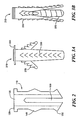
- FIGs. 3A-B another example 310 of a FAD is shown.
- the interference region is provided having a plurality of ridges or teeth 330 on an outer surface thereof
- the ridges 330 help secure the FAD within the bone hole.
- FAD 310 further includes wings 370 in the interference region which expand in response to a screw passing through the interference region and which secure the FAD within the bone hole.
- the outer walls of the FAD 310 can be ribbed, threaded or fretted to enhance the fixation of the device within the bone hole. Further the outer surface of the collar can also be ribbed, threaded or fretted to enhance the fixation of the device. As shown in to FIG.
- the interference region includes wings 375 in an end portion thereof which expand in response to a screw passing through the interference region such that when the wings are deployed, the wings engage an outer surface of the bone and increase the pull force required to remove the FAD 310 from the bone hole.
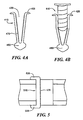
- FIGs 4A-B an example of another Fad 410 is shown.
- This example uses a "clip" style body having an aperture 430 disposed most of the way through.
- the aperture 430 includes a threaded region 470 along an inner wall.
- the threaded region helps secure a screw in the body to provide an expanding wedge type fit within the bone hole.
- a collar region 420 is disposed at a first end of the body and is disposed on the surface of the bone at a first end of the hole to secure the body in a desired location within the hole.
- a second, opposite end of the interference region has a second collar portion 450 coupled thereto.
- the second collar portion is adapted to mate to the surface of the bone at a second, opposite end of the hole.
- the second collar region helps secure the FAD 410 in the hole and increases pullout strength of the FAD.
- FIG. 5 shows a FAD useful for smaller holes.
- FAD 510 is are provided from a single member which fills only a portion of a hole in a bone.
- FAD 510 includes collar 520 and 550 on opposing ends thereof The FAD 510 may also have threads 570 provided therein. This FAD 510 function in a similar manner as those described above with respect to Figs 4A-B .
- a "split" FAD 610 is shown.
- This FAD 610 is comprised of two complimentary pieces 611 and 612, each piece representing approximately half of the FAD.
- the Fad can be comprised as a single piece which splits into two pieces upon insertion of screw 670.
- Each piece includes a respective collar portion 620, interference region 640 and flange region 650.
- the FAD is inserted into the bone hole, and upon insertion of a screw 670 the pieces 611 and 612 are separated and provide interference fit of the screw within the bone hole.
- the operation of the FAD 610 in other respects is similar to that of Figs 1A-C described above.
- a telescoping FAD 710 is shown.
- This FAD 710 includes a distal portion 730 and a proximal portion 740.
- the two portions 730 and 740 are provided having geometries such that the portions can telescope (e.g. the distal portion can move into the proximal portion).
- Screw insertion pulls the distal portion 730 into the proximal portion 740 causing expansion of the proximal portion.
- Flared out edges of the proximal portions provide the FAD having improved fixation at the proximal cortex on the intramedullary side.
- a slot 760 expands upon insertion of screw 770 and flange 750 provides for secure engagement of the FAD within the bone hole.
- FIG. 8A prior to engagement of the FAD 710, a fracture line 790 of a bone is uncompressed.
- FIG. 8B after insertion and engagement of the FAD 710, the fracture line 790 is compressed.
- an apparatus 810 for holding a FAD during a FAD or screw insertion process includes a handle 820 and a body 830 coupled to the handle.
- the body 830 is adapted to hold a FAD while the FAD is inserted in a bone hole.
- the body holds the FAD in a manner which still allows insertion of a screw into the FAD.
- the body is provided having a hole therein through which the screw can be inserted into the FAD.
- the apparatus can also include a FAD anti-rotation structure which minimizes FAD or even prevents FAD rotation which can occur when a screw is inserted into the FAD.
- the FAD can be used with a bone plate.
- the collar portion of the FAD is provided having a size and shape which allows the sleeve portion of the FAD to be inserted into a hole in a bone through a bone plate.
- the sleeve portion of the FAD fits through an opening in the bone plate and is inserted into a hole which has been drilled in a bone while the collar portion of the FAD fits through the opening in the bone plate but does not fit within the hole in the bone.
- the collar portion of the FAD can be provided having a shape which allows insertion of the FAD through the opening in the plate but which prevents rotation of the FAD during screw insertion.
- the collar portion of the FAD according to the invention is provided having an oval shape.
- the edges of the collar would make interfering contact with the walls of the plate which define the hole to thereby prevent rotation of the FAD. This would not be accomplished with a round collar. Small fins beneath the collar also help to accomplish this task.
- a first FAD 901 includes a tubular body or sleeve portion 902.
- the sleeve 902 has a collar 904 disposed on a first end thereof Collar 904 preferably has a generally oval shape that prevents rotation of the device when inserted into a bone plate or to allow a surface for a tool to use during the insertion of the device 901 or during insertion of a screw into the device 1.
- the sleeve 902 is provided having an outside diameter D 1 ( FIG. 9D ) selected such that the sleeve fits into a hole drilled in a bone.
- the collar 904 at the first or proximal end of the sleeve 902 prevents advancement of the FAD 901 into the hole with screw insertion.
- the second end of tube 902 has one or more flanges 908 coupled thereto.
- device 901 is shown having four flanges 908.
- Those of ordinary skill in the art will appreciate of course that device 901 could include fewer or more than four flanges 908.
- Surfaces 910 ( FIG. 9B ) of the flanges 908 are angled to allow the flanges to be placed in both an open position ( FIG. 9B ) and a closed position ( FIG. 9A ).
- flanges 908 expand (as shown in FIG. 9B ), providing secure fixation of the FAD 901 to the bone.
- the angled sidewalls 910 of the flanges 908 also allow the FAD 901 to be removed from the hole in the bone if desired.
- the screw is preferably withdrawn from the FAD 901 by an amount which allows the flanges 908 to collapse by an amount which allows the FAD 901 to be removed. This can be accomplished by partially unscrewing the screw from the FAD by an amount which allows the flanges to close by an amount sufficient to allow the FAD to be withdrawn from the bone.
- This amount may be a full collapse of the flanges back into the closed position. Or, it may be a partial collapse of the flanges to less than the fully closed position by an amount which still allows the FAD to be removed. Thus, in this case, the screw is not totally removed from the FAD. In some cases, however, it may be desirable or necessary to fully removed the screw from the FAD to allow the FAD to be removed.
- the FAD includes a thread 912 for receiving a screw therein.
- Thread 912 is preferably located at the distal end of body 902 and proximate ranges 908. In one embodiment, the thread 912 is located to account for a "run-in" region of a screw.
- a first surface 912a of thread 912 is spaced by a predetermined distance D 2 from a first surface 904a of the collar 904 and a second surface 912b of thread 912 is spaced by a predetermined distance D 3 from the first surface 904a of the collar 904.
- the distances D1 and D2 correspond to about .090 inches (2.29mm) and about 137 inches (3.48mm) respectively
- flange lengths L 2 correspond to about 0.157 inches (3.99mm)
- slot openings S 1 FIG. 9C
- S 1 are about .039 inches (0.991mm) and S 2 ( FIG.
- the distances D 2 and D 3 correspond to about .104 inches (2.64mm) and about .147 inches (3.73mm) respectively.
- the distances D 1 , D 2 , D 3 and D 4 correspond to about .181 inches (4.6mm), .144 inches (3.66mm), .274 inches (6.96mm) and about .312 inches (7.92mm) respectively; and the distances L2 and L3 are about .234 (5.94mm) and about .300 (7.62mm) respectively.
- junction area 916 where a flange 908 joins and emanates from body 902.
- Junction area 916 serves as a hinge or pivot point for the flanges 908.
- the junction area 916 is preferably sized to allow the flange 908 to be displaced from a closed position to an open position, and also to allow the flange 908 to be returned to the closed position from the open position. If this area is too thick, a relatively large amount of force will be required to cause the flange to open and thus it will be difficult to insert the screw. It will also be difficult to remove the FAD once the screw is removed. On the other hand, if the junction area is too small, there is a likelihood of the junction breaking, resulting in the device becoming unusable.
- the junction area 916 is preferably provided having a generally curved outer surface 917 and a generally curved inner surface 918 to reduce an occurrence of sharp bend points that could compromise the structure integrity of the junction.
- One exemplary junction area 916 is shown in FIG. 9G .
- the flanges 908 are designed to meet several criteria. While the number of flanges 908 shown in the drawings is four, any number of flanges 908 could be used depending up on the application requirements.
- the size of the flanges 908 are determined such that when the flanges 8 are in the closed position (as shown in FIG. 9A ) the flanges 908 can be inserted into a hole which has been prepared in the bone while still providing a sufficient interference fit within the hole after a screw is inserted within the device 901.
- the shape of the flanges 908 is also selected to allow sufficient interference fit when deployed ( FIG. 9B ), and further to allow the device 901 to be removed with minimal stress being placed on the bone.
- FIG. 10 An alternate embodiment of a FAD 1020 is shown in FIG. 10 .
- the FAD 1020 includes a body 1022, collar 1024, core 1026, flanges 1028 and junction points 1034 which may be similar to those described above in conjunction with FIGs. 9A-9G .
- FAD 20 has threads 32 extending substantially the length of the opening 1026. Thus, when a screw is inserted into FAD 1020, the screw remains in threaded engagement with the flanges 28 as they are deployed from a closed position to an open position.
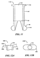
- FIG. 11 Another alternate embodiment is shown in FIG. 11 .
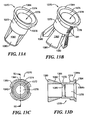
- the FAD 1140 has a similar body 1142, collar 1144, core 1146, flanges 1148 and junction points 1152 as that of the FAD 901 described above in conjunction with FIGs. 9A - 9G .
- the flanges 1148 in FAD 1140 have an engagement portion 1148 including a generally semi-circular shaped outer wall surface 1150.
- the outer wall surface 1150 provides for secure fixation of the device within a bone or plate since the semi-circular shaped ends can fit over an outer surface of the bone or plate the FAD 1140 is being affixed to.
- a collar 1262 of FAD 1260 is shown which is preferably used with a type of bone plate known as a compression plate (CP) which may, for example, be provided as Dynamic Compression Plate.
- a CP has one or more holes for receiving a screw wherein the inner surface of the screw hole has a sloped surface such that as a screw is inserted, the plate compresses the bone together.
- Collar 1262 of FAD 60 features a sloped collar surface 1264 about core 1270 to match the sloped inner surface of a hole in the CP.
- the outer edge portion 1268 has a larger cross-sectional area than outer edge portion 1266, thus providing a slope region for collar 1262.
- FAD 1370 includes a tubular body or sleeve 1372.
- the sleeve 1372 has a collar 1374 disposed on a first end thereof Collar 1374 has a generally oval shape that prevents rotation of the device when inserted into a bone plate or to allow a surface for a tool to use during the insertion of the device or during insertion of a screw into the device.
- a generally oval shoulder section 1384 is shown extending from the collar 1374.
- Shoulder 1384 has a tapered outer wall surface 1384a ( FIG. 13D ) and a tapered inner wall surface 1384b.
- FAD 1370 is preferably used with a bone plate, wherein the collar 1374 extends through a hole in the bone plate while shoulder 1384 expends into and engages an inner surface of the hole in the bone plate.
- the FAD 1370 is inserted into the bone plate hole and into the bone hole.
- FAD core 1378 When a screw is inserted into FAD core 1378, the FAD 1370 is securely engaged with the bone plate by way of shoulder 1384, while FAD 1370 itself is secured to the bone hole by flanges 1380.
- a FAD may be provided having a bone in-growth treatment 1381 applied thereto.
- the bone in-growth treatment 1381 could be a coating that is applied to the FAD, such as hydroxyapatite or could be realized as a treatment which is performed on the FAD to result in a texture surface which promotes bone in-growth to aid in securing the FAD to the bone structure.
- the bone in-growth treatment 1381 could be applied to at least a portion of one or more flanges 1382, at least a portion of the collar 1376, at least a portion of the sleeve 1372 or a combination thereof
- the use of a FAD having a bone in-growth treatment 1381 applied thereto is particularly useful in scenarios where the bone may not have a large amount of mass for a FAD to attach to or where the FAD will be used as part of a structure that may support a lot of movement or weight, for example in securing a replacement hip socket to a pelvic bone.
- the sleeve 1372 is provided having an outside diameter selected such that the sleeve fits into a hole drilled in a bone.
- the collar at the first or proximal end of the sleeve prevents advancement of the FAD 1370 into the hole with screw insertion.
- flanges 1380 expand (as shown in FIG. 13B ), providing secure fixation of the FAD 1370 to the bone.
- the angled sidewalls 1382 of the flanges 1380 are provided such that the FAD 1370 may be removed from the hole in the bone if desired. Removal of the screw from the FAD 1370 allows the flanges 1380 to be collapsed such that the FAD 1370 can be removed.
- the FAD 1370 includes a thread 86 for receiving a screw therein.
- Thread 1386 is preferably located at the distal end of body 1372 and proximate flanges 80.
- the position of the thread 1386 from the collar 1384 is selected to accommodate the run-in of the screw thread beneath the screw head and then the thread 1386 on the inner wall is preferably provided as short as possible to minimize the length of the tube portion. It could, in some applications, be desirable to lengthen the tube portion (e.g. as shown in Fig 11 ) so then the thread position may not be close at all to the flange.
- the "run-in" length assumes use with current bone screws but conceivably a screw with a minimal, or essentially no run-in, could be used in conjunction with the FAD. Also shown in FIG. 13D is the junction area 1388 where a flange 1380 emanates from body 1372.
- This junction area 1388 serves as the hinge or pivot point for the flanges 1380.
- the junction area is preferably sized and located relative to the flanges to allow the flanges to be displaced from a closed position to an open position, and also to allow the flanges to be returned to the closed position from the open position.
- the thickness of the wall in the junction area should preferably be selected to allow the flanges 1380 to move from a closed position to an open position and then back to a closed position again if necessary. If the junction area is too thick, it will be difficult to insert the screw and to obtain the desired purchase within the bone and it will also be difficult to remove the FAD once the screw is removed.
- junction area 1388 is preferably provided having a generally curved outer surface and a generally curved inner surface to reduce an occurrence of sharp bend points that could compromise the junction.
- the flanges 1380 are designed to meet several criteria. While the number of flanges shown in the drawings is four, any number of flanges could be used depending on the application requirements.
- the size of the flanges are determined such that when the flanges are in the closed position the flanges can be inserted into the drill hole while still providing a sufficient interference fit within the hole of the bone when a screw is inserted within the device.
- the shape of the flanges is also selected to allow sufficient interference fit when deployed, and further to allow the device to be removed with minimal stress being placed on the bone.
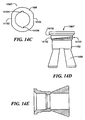
- FAD 1490 another embodiment of a FAD 1490 is shown.
- the FAD in this embodiment is similar to FAD 1370 described above in connection with FIGs. 13A-13D above and has some additional features.
- FAD 1490 includes a sleeve 1492, a core 1494, flanges 1496 and a collar 1498, generally similar to the FADs described above in conjunction with Figs. 9A-13D .
- Collar 1498 is provided with an external thread 100 which is used to attach the FAD to a bone plate and to prevent the FAD from rotating within the bone or bone plate when a screw is inserted into the core 1494.
- Collar 1498 is also provided with a flat outer surface portion 14102.
- Collar 1498 further includes a slot 14104 disposed across an inner surface of the collar 1494.
- the slot 14104 accommodates a flat blade of a screw driver.
- a screw driver can be used to rotate the FAD 1490 by way of slot 14104 to unblock the FAD from the bone plate, such that the FAD 1490 could then be removed.
- FAD 1490' is similar to Fad 1490 and includes a sleeve 1492, a core 1494, flanges 1496 and a collar 1498'.
- Collar 1498' is also provided with an external thread 14100 which is used to attach the FAD to a bone plate and to prevent the FAD from rotating within the bone or bone plate when a screw is inserted into core 1494.
- Collar 1498 further includes a slot 14104 disposed across an inner surface of the collar 1494.
- Collar 1498' is provided with multiple flat outer surface portions 14102. These multiple flat outer surface portions provide a place for an anti-rotation device to secure the FAD while a screw is removed from core 1494.
- FAD 1490 is similar to Fad 1490 and includes a sleeve 1492, a core 1494, flanges 1496 and a collar 1498.
- Collar 1498 is provided with an external thread 14100 which is used to attach the FAD to a bone plate and to prevent the FAD from rotating within the bone or bone plate when a screw is inserted into core 1494.
- Collar 1498 further includes a slot 104 disposed across an inner surface of the collar 1494.
- Collar 1498 is provided with multiple flat outer surface portions 14102. These multiple flat outer surface portions provide a place for an anti-rotation device to secure the FAD while a screw is removed from core 1494.
- the collar includes a tapered outer surface portion 14106. The tapered outer surface portion 14106 is used for mating with a bone plate having a hole with a corresponding tapered or counter-sunk inner surface.
- the FADs described herein are preferably comprised of stainless steel although other materials such as titanium or a bio-absorbable material having acceptable mechanical properties could be used. Also, plastics such a polymethylmethacrylate (PMMA) or other biocompatible plastics can also be used. According to the invention the FAD collar portion is provided having an oval shape used.
- the FAD can be used with a bone plate.
- the collar portion of the FAD is provided having a size and shape that allows the sleeve portion of the FAD to be inserted into a hole in a bone through a bone plate.
- the sleeve portion of the FAD fits through an opening in the bone plate and is inserted into a hole which has been drilled in a bone while the collar portion of the FAD fits through the opening in the bone plate but does not fit within the hole in the bone.
- the collar portion of the FAD can be provided having a shape which allows insertion of the FAD through the opening in the plate but which prevents rotation of the FAD during screw insertion.
- the collar portion of the FAD according to the invention is provided having an oval shape.
- the edges of the collar would make interfering contact with the walls of the plate that define the hole to thereby prevent rotation of the FAD. This would not be accomplished with a round collar.
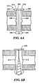
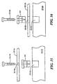
- one possible procedure for FAD installation includes aligning a bone plate over a bone, using existing holes in the bone plate as a guide to drill one or more holes into (and partially or fully) through the bone. With the bone plate aligned over the holes, the FAD is disposed through the hole in the bone plate and into the hole which was drilled in the bone. A screw 15118 is then inserted through the hole 15116 in the bone plate 14114 and into the FAD 901. As the screw advances, the flanges of the FAD 901 expand giving interference fixation to the bone along the inner walls of the drill hole 15112. Once the screw 15118 is fully seated, secure fixation of the bone plate 15114 to the bone 15110 is established.
- Another possible procedure for FAD installation includes is described. Once a surgeon or other medical practitioner has determined that a FAD is required, a hole 15112 is drilled into bone 15110 utilizing an appropriately sized drill for the FAD 901 being used. The FAD 901 is then placed into the drill hole 15112. The bone plate 15114 is then positioned on bone 15110 such that the hole 15116 in bone plate 15114 is aligned with the hole in FAD 901. Once aligned, a screw 15118 is inserted through the hole 15116 in bone plate 15114 and into the FAD 901. As the screw advances, the flanges of the FAD 901 expand giving interference fixation to the bone along the inner walls of the drill hole 15112. Once the screw 15118 is fully seated, secure fixation of the bone plate 15114 to the bone 15110 is established.
- FIG. 16 an alternate procedure for FAD installation is shown.
- a hole 16122 is drilled into bone 16120 utilizing an appropriately sized drill for the FAD 901 being used.
- the bone plate 16124 is then positioned on bone 16120 such that the hole 16126 in bone plate 16124 is aligned with the hole 16122 in the bone 16120.
- the FAD 901 is then placed into and extending through the hole 16126 of bone plate 16124 and into the drill hole 16122 of bone 16120.
- a screw 16128 is inserted into the FAD 901. As the screw advances, the flanges of the FAD 901 expand giving interference fixation to the bone along the inner walls of the drill hole 16122. Once the screw 16128 is fully seated, secure fixation of the bone plate 16124 to the bone 16120 is established.
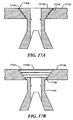
- Locking plate 17132 is similar to bone plate 17124 shown in FIG. 16 , except that the hole 17136 in locking plate 17132 has threaded, tapered side walls 17134. The threaded tapered side walls 17134 mate with a threaded external surface 17138 of FAD 17130.
- the FAD 17130 is inserted into the hole 17136 and rotated a predetermined amount to securely mate the FAD 17130 within the locking plate 17132.
- a top surface of the inserted FAD 17130 is generally coplanar with the top surface of the locking plate 17132.
- FIG. 17B an embodiment of a FAD 17142 which is also used with a locking plate 17132 is shown.
- the threaded tapered side walls 17134 of hole 17136 in locking plate 17132 mate with a threaded external surface 17138 of FAD 17142.
- the FAD 17142 is inserted into the hole 17136 and rotated a predetermined amount to securely mate the FAD 17142 within the locking plate 17132.
- a top surface of the inserted FAD 17142 is recessed within hole 17136. This allows for a screw (not shown) inserted into FAD 17142 to have it's top surface be generally co-planar with the top surface of locking plate 17132 when the screw is completely inserted into the FAD 17142.
- a device 17150 which comprises at least one FAD portion and a bone plate portion integrated together as a single unitary device.
- the device 17150 includes a bone plate portion 17152 and one or more FAD portions 17154.
- a FAD portion 17154 includes a sleeve 17156, flanges 17158, and a core 17160.
- This device 17150 replaces a combination of a bone plate and separate FAD devices with a single unitary device providing similar functionality.
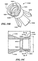
- FIGs. 19A - 19H in which like elements are provided having like reference designations throughout the several views, another embodiment of a FAD 19190 is shown.
- the FAD in this embodiment is similar to FAD 1490 described above in conjunction with FIGs. 14A - 14D but has some additional features including a release cam lock mechanism as will be described below.
- the FAD 19190 includes a sleeve 19192, a core 19194, flanges 19196 and a collar 19198, generally similar to FADs described above and a release cam lock mechanism 19200.
- the Collar 19198 is provided having a pair of openings 19202.
- the openings 19202 are provided having a size and shape selected to accept a removal tool.
- the openings 19202 are provided having a rectangular-slot shape which accepts a flat tip of a removal tool. This aids in placing the device 19190 in proper alignment within a bone plate hole during insertion and removal of the device 19190.
- the holes 19202 are aligned with the major (i.e. the longer) axis of the oval hole of the plate. This alignment insures that the device 19190 will seat properly in the bone plate during insertion as it is aligned with the oval shape of the locking mechanism 19200 beneath the collar 19198. With screw insertion and seating, the device 19190 rotates into a locked position on the plate and the holes 19202 show the orientation of the device 19190 to have rotated in the direction of the minor (i.e. the shorter) axis of the oval hole in the bone plate.
- the removal tool can be used to re-orient the openings 19202 of the device 19190 so they are once again aligned with the major axis of the oval hole in the bone plate. This insures that the device 19190 is no longer locked onto the plate and can be safely removed.
- Flat surfaces 19204 on the collar 19198 are present to allow use of an anti-rotation tool if needed during supplement insertion and removal.
- the anti-rotation tool is a device used to prevent the device 19190 from rotating during the screw insertion and removal processes.
- the flat surfaces also provide a visual cue to properly align the device 190 during insertion and removal of the device 19190. Similar to the slot 19202 in the collar 19198, the flat collar surfaces 19204 are aligned with the major axis of an oval hole in a bone plate during initial insertion and just prior to removal. This alignment insures that the device 19190 is no longer locked onto the plate as occurs when the supplement rotates slightly with screw insertion and seating as will become apparent from the description of FIG. 20 hereinbelow.
- the locking mechanism 19200 includes the collar 19198, one or more expansion or cam regions 19206 beneath the collar 19198 and a tab 19208 which is below the collar 19198 and expansion regions 19206.
- the embodiment shown in FIGs. 19A-19H two cam regions 19206 are shown (best seen in FIG. 19E ).
- the cam regions 19206 are provided in a cam arrangement with an offset from the device centerline by approximately .002 inches (0.0508mm).
- the length L 1 ( FIG. 19E ) is in the range of about .188 (4.78mm) to about .190 inches (4.83mm) and the about and the length L 2 ( FIG. 19E ) is in the range of about .166 (4.22mm) inches to about .168 inches (4.27mm).
- the lengths L 3 ( FIG. 19D ) and L 4 ( FIG. 19D ) of the tab region are in the range of about .190 (4.83mm) to about .200 inches (5.08mm) and in the range of about .164 (4.17mm) to about .166 inches (4.22mm), respectively.
- the expansion areas can be provided by having a portion of the sleeve 19192 made to have an oval shape or by having a portion of the sleeve 19192 made to have a cam-type arrangement as described above.
- the expansion areas 19206 are slightly misaligned with the tab 19208. This slight misalignment allows the tab 19208 to move underneath the plate (e.g. plate 20216 in FIG. 20 ) prior to the cam regions 19206 contacting a surface of the hole in the compression plate. This prevents further rotation of the FAD in the hole of the compression plate.
- a FAD having an overall length of about .3 inches (7.62mm) i.e.
- the thickness T 1 of the expansion area 20206 is in the range of about .032 inches (0.813mm) and the thickness T 2 of the tab 20206 is in the range of about .009 inches (0.229mm).
- Other thickness and axis lengths for the expansion and tab regions may also be used depending upon the needs of any particular application.
- the major axes of the expansion area and tab are offset by about three and on-half degrees although offsets in the range of about one to about thirty degrees may be used depending upon a variety of factors including the size of the FAD (including the lengths of the major and minor axes of both the expansion region and tabs) as well as the lengths of the major and minor axes of the hole in the compression plate (or other structure) in which the FAD will be disposed.
- the device 19190 rotates with screw insertion and the tab 19208 feeds underneath the plate (e.g. plate 20216 in FIG. 20 ). This prevents the device 19190 from moving up and down within the plate hole and insures proper contact of the plate and device 19190.
- the expansion area 19206 is positioned with respect to the tab 20208 such that upon rotation of the device, the expansion area 19206 contacts an inner wall or surface (e.g. wall 20214a in FIG. 20 ) of the plate hole just after the tab 19206 feeds under the plate (e.g. plate 20216 in FIG. 20 ).
- the long axes for both the oval expansion and the tabs are short enough relative to the long axis of the oval plate hole to allow easy seating of the supplement during insertion of the device (i.e. both the tab and the expansion have to fit and the length of the major axis for the tab is slightly greater that the length of the major axis for the expansion).
- the device 19190 may also be provided having features above such as flat (rather than beveled) internal and/or external collar surfaces.
- the FAD 19190 may be provided having a bone in-growth treatment such as that described above.
- the bone in-growth treatment could be a coating that is applied to the FAD, or could be realized as a treatment which is performed on the FAD to result in a textured surface which promotes bone in-growth to aid in securing the FAD to the bone structure.
- the bone in-growth treatment could be applied to at least a portion of one or more flanges 19196 (either inner or outer flange surfaces), at least a portion of the collar 19198, at least a portion of the sleeve 19192 or a combination thereof
- the use of a FAD having a bone in-growth treatment applied thereto is particularly useful in scenarios where the bone may not have a large amount of mass for a FAD to attach to or where the FAD will be used as part of a structure that may support a lot of movement or weight, for example in securing a replacement hip socket to a pelvic bone.
- the FAD 19190 has an overall length L ( FIG. 19C ) of about .340 inches (8.64mm) a lower diameter D 1 ( FIG. 19I ) in the range of about .254 inches (6.45mm), a flange diameter D 2 ( FIG. 19C ) of about .250 (6.35mm) in and slot openings S 1 ( FIG. 19H ) in the range of about .039 inches (0.991mm) and S 2 ( FIG. 19H ) in the range of about .090 inches (2.29mm).
- Other lengths, diameters and slot sizes may, of course, also be used.
- flange diameters to be use in any particular application will be determined in accordance with a variety of factors including but not limited to the length and diameter of screws being inserted.
- the particular size of slot openings to be used in any application will be determined in accordance with a variety of factors including but not limited to the length and overall diameter of the FAD as well as the length and diameter of screws being inserted into the FAD.
- a portion of a bone 20206 is shown to include an upper bone region 20210a, a lower bone region 20210b and a space region 20212 between the upper and lower bone regions 20210a, 20210b.
- a hole 20214 is provided through both the upper and lower bone regions 20210a, 20210b.
- the hole 20214 may be referred to as a "through hole” meaning that the hole provides a path through the entire bone 20206.
- the hole 20214 need only pass through one bone portion (e.g. either bone portion 20210a or 20210b). Those of ordinary skill in the art will appreciate how to determine whether the hole 20214 should be provided to pass through only one of the bone regions 20210a, 20210b or whether it should pass through all regions of a bone (e.g. through both regions 20210a, 20210b of bone 20206.
- a plate 20216 (e.g. a bone or compression plate) having an hole therein is disposed over the bone portion 20210a with the plate hole aligned with the hole 20214 in the bone portion 20210a. Once the plate hole and bone hole 214 are aligned, the device 19190 is disposed in the hole 214. The device 19190 can then be turned such that the collar 19198 engages a first surface of the plate 20216 and the tab 19208 engages a second surface of the plate.
- the device 19190 can then be turned such that the collar 19198 engages a first surface of the plate 20216 and the tab 19208 engages a second surface of the plate.
- the hole 20214 in the plate 20216 is provided having an oval shape and the major axis of the expansion area 19206 (most clearly seen in FIG. 19E ) of the device 19190 is longer than the minor axis of the oval hole in the plate 20216.
- the major axis of the expansion area 19206 of the device 19190 is longer than the minor axis of the oval hole in the plate and by providing the expansion area 19206 in a predetermined spatial relationship with respect to the tabs 19208, once the tabs 19208 engage the surface of the plate 20216, the expansion area 19206 prevents further rotation of the device 19190 in the hole 20214.
- a screw 20217 having a head portion 20218 and a body portion 20220 is disposed in the device 19190. Insertion of the screw in the device 19190 causes the flanges 19196 to open and secure the device 19190 in the hole and in particular in the space region 20212 of the bone 20206.
- the device 19190 also includes the thread region 19222 which engages threads 20224 provided in the screw body 20220. The screw threads 20224 engage the thread 19222 which, in combination with the opened flanges 19196, allows the screw 20216 to be securely coupled to the bone 20206.
- a space 20230 may exist between a bottom surface of the plate and a surface of the bone 20210b, however, this space 20230 has substantially no impact on the ability of FAD 19190, plate 20216 or screw 20220 to serve their respective intended functions.
Landscapes
- Health & Medical Sciences (AREA)
- Orthopedic Medicine & Surgery (AREA)
- Surgery (AREA)
- Life Sciences & Earth Sciences (AREA)
- Molecular Biology (AREA)
- Animal Behavior & Ethology (AREA)
- Engineering & Computer Science (AREA)
- Biomedical Technology (AREA)
- Heart & Thoracic Surgery (AREA)
- Medical Informatics (AREA)
- Neurology (AREA)
- Nuclear Medicine, Radiotherapy & Molecular Imaging (AREA)
- General Health & Medical Sciences (AREA)
- Public Health (AREA)
- Veterinary Medicine (AREA)
- Surgical Instruments (AREA)
- Dowels (AREA)
- Vessels, Lead-In Wires, Accessory Apparatuses For Cathode-Ray Tubes (AREA)
- Golf Clubs (AREA)
- Clamps And Clips (AREA)
Claims (10)
- Fixierungs-Verstärkungsvorrichtung, die dazu angepasst ist, in eine Knochenplatte eingeführt zu werden und Folgendes umfasst:einen allgemein röhrenförmigen Körper (19 192) mit einer Öffnung (19 194), die dazu angepasst ist, eine Schraube (202 17) darin aufzunehmen; undeine an einem ersten Ende des genannten Körpers angebrachte Manschette (19 198), wobei die Außenwandoberfläche der Manschette (19 198) eine nicht kreisförmige Form hat und eine Öffnung hat, die mit der Öffnung im genannten Körper ausgerichtet ist, und wobei:mehrere Flansche (19 196) an einem zweiten Ende des genannten Körpers angeordnet sind, wobei die Flansche (19 196) jeweils als Reaktion auf das Einführen einer Schraube in die Öffnung (19 194) des genannten Körpers vom genannten Körper ausweitbar sind;dadurch gekennzeichnet, dass die Außenwandoberfläche der genannten Manschette (19 198) mit einer ovalen Form vorgesehen ist.
- Vorrichtung nach Anspruch 1, dadurch gekennzeichnet, dass die genannte Manschette (19 198) eine unregelmäßige Breite hat.
- Vorrichtung nach Anspruch 1 oder 2, dadurch gekennzeichnet, dass eine Außenwand der genannten Manschette (19 198) eine allgemein konische Oberfläche hat.
- Vorrichtung nach einem der vorangehenden Ansprüche, dadurch gekennzeichnet, dass eine Innenwand der genannten Manschette (19 198) eine allgemein konische Oberfläche hat.
- Vorrichtung nach Anspruch 1, dadurch gekennzeichnet, dass eine Außenwand der genannten Flansche eine allgemein flache Oberfläche hat.
- Vorrichtung nach Anspruch 1, dadurch gekennzeichnet, dass eine Außenwand der genannten Flansche eine allgemein halbkreisförmige Oberfläche hat.
- Vorrichtung nach Anspruch 1, dadurch gekennzeichnet, dass eine Innenfläche des genannten Körpers, die die zum Aufnehmen einer Schraube angepasste Öffnung definiert, mit einem davon vorstehenden Gewinde (19 222) ausgestattet ist, wobei das genannte Gewinde dazu angepasst ist, mit der Schraube in Eingriff zu treten.
- Vorrichtung nach Anspruch 1, dadurch gekennzeichnet, dass eine Innenfläche des genannten Körpers, die die Öffnung darin definiert, mit einem sich ungefähr über die Länge des genannten Körpers erstreckenden Innengewindeabschnitt ausgestattet ist, wobei der genannte Gewindeabschnitt dazu angepasst ist, mit einer Schraube in Eingriff zu treten.
- Vorrichtung nach Anspruch 1, gekennzeichnet durch eine Knochenplatte, wobei die genannte Knochenplatte (20 216) ein dadurch verlaufendes Knochenplattenloch hat, wobei das genannte Knochenplattenloch eine vorherbestimmte Größe hat, die so ausgewählt ist, dass der genannte röhrenförmige Körper darin aufgenommen werden kann und dass die genannte Manschette nicht durch das Knochenplattenloch passt.
- Vorrichtung nach Anspruch 1, dadurch gekennzeichnet, dass die genannte Manschette (19 198) mit einem Auslösenockenmechanismus (19 200) ausgestattet ist.
Applications Claiming Priority (2)
| Application Number | Priority Date | Filing Date | Title |
|---|---|---|---|
| US46882903P | 2003-05-08 | 2003-05-08 | |
| PCT/US2004/014640 WO2004100809A1 (en) | 2003-05-08 | 2004-05-10 | Fixation augmentation device and related techniques |
Publications (2)
| Publication Number | Publication Date |
|---|---|
| EP1624816A1 EP1624816A1 (de) | 2006-02-15 |
| EP1624816B1 true EP1624816B1 (de) | 2010-08-11 |
Family
ID=33452234
Family Applications (1)
| Application Number | Title | Priority Date | Filing Date |
|---|---|---|---|
| EP04751838A Expired - Lifetime EP1624816B1 (de) | 2003-05-08 | 2004-05-10 | Befestigungs und verstärkungs-mittel und zugehörige techniken |
Country Status (6)
| Country | Link |
|---|---|
| US (1) | US8419780B2 (de) |
| EP (1) | EP1624816B1 (de) |
| JP (1) | JP4771953B2 (de) |
| AT (1) | ATE476927T1 (de) |
| DE (1) | DE602004028600D1 (de) |
| WO (1) | WO2004100809A1 (de) |
Families Citing this family (72)
| Publication number | Priority date | Publication date | Assignee | Title |
|---|---|---|---|---|
| US8506605B2 (en) * | 2002-09-18 | 2013-08-13 | Simplicity Orthopedics, Inc. | Method and apparatus for securing an object to bone and/or for stabilizing bone |
| DE102004035546A1 (de) * | 2004-07-19 | 2006-02-16 | Wolter, Dietmar, Prof. Dr.Med. | Fixationssystem für Knochen und Füllkörper für ein Fixationssystem für Knochen |
| WO2006039636A2 (en) * | 2004-10-01 | 2006-04-13 | Simmons Edward D | Screw sleeve made of polyetheretherketone (peek) |
| ES2303037T3 (es) * | 2004-11-29 | 2008-08-01 | Stryker Trauma Sa | Dispositivo de extraccion para un inserto de un elemento de conexion oseo y un inserto. |
| US20060217717A1 (en) * | 2005-03-24 | 2006-09-28 | Dale Whipple | Methods and devices for stabilizing a bone anchor |
| US8128670B2 (en) * | 2005-04-15 | 2012-03-06 | Biodynamics Llc | Surgical expansion fasteners |
| US20080221623A1 (en) * | 2005-10-17 | 2008-09-11 | Gooch Hubert L | Systems and Methods for the Medical Treatment of Structural Tissue |
| US20070118131A1 (en) * | 2005-10-17 | 2007-05-24 | Gooch Hubert L | Anchor for Augmentation of Screw Purchase and Improvement of Screw Safety in Pedicle Screw Fixation and Bone Fracture Fixation Systems |
| US20080221624A1 (en) * | 2005-10-17 | 2008-09-11 | Gooch Hubert L | Systems and Methods for the Medical Treatment of Structural Tissue |
| US20110160766A1 (en) * | 2005-11-02 | 2011-06-30 | Hendren Ronald D | Medical Affixation Device |
| US7670341B2 (en) | 2005-12-16 | 2010-03-02 | Depuy Products, Inc. | Orthopaedic device with locking barrel |
| WO2008133883A2 (en) * | 2007-04-23 | 2008-11-06 | Simplicity Orthopedics, Inc. | Method and apparatus for securing an object to bone |
| JP2010528706A (ja) * | 2007-06-01 | 2010-08-26 | シンプリシティ・オーソペディックス・インコーポレーテッド | 物を骨に固定するため及び/叉は骨を安定にするための方法及び装置 |
| US7604640B2 (en) * | 2007-06-14 | 2009-10-20 | Zimmer Spine Austin, Inc. | Device and system for applying rotary impact |
| WO2009062163A1 (en) * | 2007-11-09 | 2009-05-14 | Simplicity Orthopedics, Inc. | Method and apparatus for securing an object to bone and/ or for stabilizing bone |
| EP2231043B1 (de) | 2007-12-17 | 2014-06-04 | Synthes GmbH | Dynamisches knochenbefestigungselement |
| JP2011525229A (ja) * | 2008-06-19 | 2011-09-15 | ジンテス ゲゼルシャフト ミット ベシュレンクテル ハフツング | 骨ネジの足掛かり増強インプラント、システム、及び技術 |
| WO2010040002A1 (en) * | 2008-10-01 | 2010-04-08 | Life Spine, Inc. | Spinal facet fastener |
| US20100114174A1 (en) * | 2008-10-30 | 2010-05-06 | Bryan Jones | Systems and Methods for Delivering Bone Cement to a Bone Anchor |
| US8157865B2 (en) | 2009-01-22 | 2012-04-17 | Stephen Hochschuler | Apparatus and method for stabilizing adjacent bone portions |
| US8574271B2 (en) * | 2009-07-29 | 2013-11-05 | Paul Andrew Glazer | Fixation plate screw retention |
| US9480511B2 (en) | 2009-12-17 | 2016-11-01 | Engage Medical Holdings, Llc | Blade fixation for ankle fusion and arthroplasty |
| EP2525745A4 (de) * | 2010-01-22 | 2013-08-07 | Stephen Hochschuler | Vorrichtung und verfahren zur stabilisierung von aneinanderliegenden knochenteilen |
| AU2011258241A1 (en) | 2010-05-26 | 2013-01-10 | Orbis Medical Group Llc | Implantable prostheses |
| US9724140B2 (en) | 2010-06-02 | 2017-08-08 | Wright Medical Technology, Inc. | Tapered, cylindrical cruciform hammer toe implant and method |
| US9498273B2 (en) | 2010-06-02 | 2016-11-22 | Wright Medical Technology, Inc. | Orthopedic implant kit |
| US8608785B2 (en) | 2010-06-02 | 2013-12-17 | Wright Medical Technology, Inc. | Hammer toe implant with expansion portion for retrograde approach |
| JP6022465B2 (ja) * | 2010-10-27 | 2016-11-09 | シンセス ゲゼルシャフト ミット ベシュレンクテル ハフツングSynthes Gmbh | 骨インプラント |
| US9925051B2 (en) | 2010-12-16 | 2018-03-27 | Engage Medical Holdings, Llc | Arthroplasty systems and methods |
| WO2012125704A2 (en) * | 2011-03-14 | 2012-09-20 | Topsfield Medical Gmbh | Implantable glenoid prostheses |
| US9161794B2 (en) | 2011-04-14 | 2015-10-20 | Globus Medical, Inc. | Expanding spinal anchor |
| US9901378B2 (en) * | 2011-07-29 | 2018-02-27 | Aesculap Ag | Surgical instrumentation for spinal surgery |
| US9155580B2 (en) | 2011-08-25 | 2015-10-13 | Medos International Sarl | Multi-threaded cannulated bone anchors |
| DE102011053295A1 (de) | 2011-09-06 | 2013-03-07 | Aesculap Ag | Polyaxiale Pedikelschraube mit provisorischer Fixierung |
| US9615856B2 (en) | 2011-11-01 | 2017-04-11 | Imds Llc | Sacroiliac fusion cage |
| US9254130B2 (en) | 2011-11-01 | 2016-02-09 | Hyun Bae | Blade anchor systems for bone fusion |
| US11123117B1 (en) * | 2011-11-01 | 2021-09-21 | Nuvasive, Inc. | Surgical fixation system and related methods |
| US10039556B2 (en) | 2011-11-10 | 2018-08-07 | David Michael Burt | Arthroscopic total shoulder arthroplasty |
| US9839435B2 (en) | 2011-11-14 | 2017-12-12 | The University Of British Columbia | Intramedullary fixation system for management of pelvic and acetabular fractures |
| US9554914B2 (en) * | 2011-12-12 | 2017-01-31 | Wright Medical Technology, Inc. | Fusion implant |
| CA2867269A1 (en) | 2012-03-13 | 2013-09-19 | DePuy Synthes Products, Inc. | Dynamic bone fixation element |
| US10238382B2 (en) | 2012-03-26 | 2019-03-26 | Engage Medical Holdings, Llc | Blade anchor for foot and ankle |
| FR2996115B1 (fr) | 2012-10-03 | 2015-05-29 | Biotech Ortho | Soutien de vis orthopedique. |
| US8945232B2 (en) | 2012-12-31 | 2015-02-03 | Wright Medical Technology, Inc. | Ball and socket implants for correction of hammer toes and claw toes |
| AU2014287772B2 (en) * | 2013-07-10 | 2019-03-28 | Smith & Nephew, Inc. | Distal tip two piece external expansion anchor |
| US9724139B2 (en) | 2013-10-01 | 2017-08-08 | Wright Medical Technology, Inc. | Hammer toe implant and method |
| US9474561B2 (en) | 2013-11-19 | 2016-10-25 | Wright Medical Technology, Inc. | Two-wire technique for installing hammertoe implant |
| US9545274B2 (en) * | 2014-02-12 | 2017-01-17 | Wright Medical Technology, Inc. | Intramedullary implant, system, and method for inserting an implant into a bone |
| US9498266B2 (en) | 2014-02-12 | 2016-11-22 | Wright Medical Technology, Inc. | Intramedullary implant, system, and method for inserting an implant into a bone |
| WO2015134750A1 (en) | 2014-03-06 | 2015-09-11 | University Of British Columbia | Shape adaptable intramedullary fixation device |
| US9907593B2 (en) | 2014-08-05 | 2018-03-06 | Woven Orthopedic Technologies, Llc | Woven retention devices, systems and methods |
| WO2016043751A1 (en) | 2014-09-18 | 2016-03-24 | Wright Medical Technology, Inc. | Hammertoe implant and instrument |
| EP4245233A3 (de) | 2014-10-14 | 2023-12-06 | The University of British Columbia | Systeme zur intramedullären knochenfixierung |
| CA2889595C (en) | 2014-12-19 | 2018-01-16 | Wright Medical Technology, Inc. | Intramedullary anchor for interphalangeal arthrodesis |
| EP3267912A4 (de) * | 2015-03-12 | 2019-01-16 | Spinal Balance, Inc. | Pedikelrekonstruktionsvorrichtung |
| WO2017024277A1 (en) | 2015-08-05 | 2017-02-09 | Woven Orthopedic Technologies, Llc | Tapping devices, systems and methods for use in bone tissue |
| EP3498205B1 (de) * | 2016-08-10 | 2022-04-27 | Beijing AK Medical Co., Ltd. | Befestigungssystem für künstlichen wirbelkörper |
| CN106420032B (zh) * | 2016-08-31 | 2019-07-26 | 苏州西脉新诚生物科技有限公司 | 一种多脚扣合骨螺钉 |
| US10390955B2 (en) | 2016-09-22 | 2019-08-27 | Engage Medical Holdings, Llc | Bone implants |
| CN117257430A (zh) | 2016-10-05 | 2023-12-22 | 不列颠哥伦比亚大学 | 带有形状锁定交接部的髓内固定装置 |
| US11395681B2 (en) | 2016-12-09 | 2022-07-26 | Woven Orthopedic Technologies, Llc | Retention devices, lattices and related systems and methods |
| US11540928B2 (en) | 2017-03-03 | 2023-01-03 | Engage Uni Llc | Unicompartmental knee arthroplasty |
| US10456272B2 (en) | 2017-03-03 | 2019-10-29 | Engage Uni Llc | Unicompartmental knee arthroplasty |
| IT201800009413A1 (it) * | 2018-10-12 | 2020-04-12 | Limacorporate Spa | Componente di protesi articolare, relativo strumentario chirurgico di lavorazione dell’osso e metodo di realizzazione della protesi |
| EP3866712A1 (de) | 2018-10-17 | 2021-08-25 | Curvafix, Inc. | Intramedulläre fixiervorrichtung |
| US11832856B2 (en) | 2018-10-17 | 2023-12-05 | The University Of British Columbia | Bone-fixation device and system |
| US11426285B2 (en) * | 2019-09-05 | 2022-08-30 | Howmedica Osteonics Corp. | Truss glenoid augment |
| AT524170A1 (de) * | 2020-09-07 | 2022-03-15 | V I E Systems Gmbh | Platte zur Plattenosteosynthese, Befestigungselement und Set |
| US20220104949A1 (en) * | 2020-10-02 | 2022-04-07 | Facet Mobility, Llc | Artificial spinal prosthesis and method |
| KR102689316B1 (ko) * | 2022-01-26 | 2024-07-30 | 주식회사 에어스 | 푸쉬타입 한쪽 피질골 고정 앵커 |
| US12588930B2 (en) | 2022-02-04 | 2026-03-31 | Curvafix, Inc. | Devices, systems, and methods of use for delivery of materials in combination with intramedullary devices |
| US12514618B2 (en) * | 2022-04-01 | 2026-01-06 | Globus Medical Inc. | Expandable bone core for pedicle screw fixation |
Family Cites Families (52)
| Publication number | Priority date | Publication date | Assignee | Title |
|---|---|---|---|---|
| US1752752A (en) | 1923-05-03 | 1930-04-01 | Edward Ogden Company J | Expansion shield |
| GB552133A (en) | 1940-11-05 | 1943-03-24 | British Celanese | Improvements relating to textile fabrics |
| US2381050A (en) | 1943-12-04 | 1945-08-07 | Mervyn G Hardinge | Fracture reducing device |
| US3174387A (en) | 1962-06-04 | 1965-03-23 | Fischer Artur | Expansion bolt |
| US3232163A (en) | 1963-05-16 | 1966-02-01 | United Shoe Machinery Corp | Plastic screw anchor |
| US3473222A (en) | 1968-05-31 | 1969-10-21 | Lynn C Kester | Denture anchor |
| DE2250501C3 (de) | 1972-10-14 | 1975-04-30 | Artur 7241 Tumlingen Fischer | Befestigungsmittel fur die Pfanne einer Huftgelenkprothese |
| FR2431060A1 (fr) * | 1978-07-13 | 1980-02-08 | Itw De France | Piece de fixation imperdable et reutilisable |
| US4201531A (en) | 1979-01-02 | 1980-05-06 | The Plastic Forming Company, Inc. | Reinforced bearing aperture in thermoplastic sheet material |
| US4312612A (en) | 1979-05-31 | 1982-01-26 | United Packages Limited | Screw fixing device |
| CH645168A5 (en) | 1980-05-03 | 1984-09-14 | Kunckel Johann | Self-locking screw anchor, in particular for insertion into end-grain wood |
| CH648197A5 (de) | 1980-05-28 | 1985-03-15 | Synthes Ag | Implantat und zu dessen befestigung an einem knochen dienende schrauben. |
| FR2523228B1 (fr) | 1982-03-10 | 1986-02-28 | Bucz Jean | Chevilles a douilles expansibles |
| US4553273A (en) * | 1983-11-23 | 1985-11-19 | Henry Ford Hospital | Vertebral body prosthesis and spine stabilizing method |
| US4611581A (en) | 1983-12-16 | 1986-09-16 | Acromed Corporation | Apparatus for straightening spinal columns |
| US4601625A (en) | 1984-05-11 | 1986-07-22 | Illinois Tool Works Inc. | Self drilling threaded insert for drywall |
| DE3445738A1 (de) | 1984-12-14 | 1986-06-19 | Draenert Klaus | Implantat zur knochenverstaerkung und verankerung von knochenschrauben, implantaten oder implantatteilen |
| CN1006954B (zh) | 1985-03-11 | 1990-02-28 | 阿图尔·费希尔 | 用于骨接合术的紧固元件 |
| US4828562A (en) | 1988-02-04 | 1989-05-09 | Pfizer Hospital Products Group, Inc. | Anterior cruciate ligament prosthesis |
| DE8908858U1 (de) | 1989-07-18 | 1989-12-14 | Eternit Ag, 1000 Berlin | Fassadenplatte mit Befestigungsvorrichtung |
| US5725529A (en) | 1990-09-25 | 1998-03-10 | Innovasive Devices, Inc. | Bone fastener |
| FR2676356A1 (fr) | 1991-05-13 | 1992-11-20 | Cendis Medical | Element de fixation pour ligaments. |
| DE4140512C1 (de) | 1991-12-09 | 1993-04-08 | A. Raymond & Cie, Grenoble, Fr | |
| DE4201531A1 (de) | 1992-01-17 | 1993-07-22 | Schubert Werner | Vorrichtung fuer die verfestigung von knochenbruechen |
| GB2266246B (en) * | 1992-03-27 | 1996-08-07 | Jesse Shirley & Son Limited | Fracture fixation device |
| EP0596829B1 (de) | 1992-11-02 | 2000-11-22 | Sulzer Orthopädie AG | Verankerung für ein künstliches Band |
| JP2586907Y2 (ja) * | 1992-11-19 | 1998-12-14 | 株式会社ニフコ | 結合クリップ |
| US5324292A (en) * | 1993-02-10 | 1994-06-28 | Zimmer, Inc. | Fracture fixation assembly with selectively removable protrusion |
| IT1263895B (it) | 1993-02-11 | 1996-09-05 | Giuseppe Vrespa | Perno-moncone amovibile per impianti endossei |
| US5380334A (en) | 1993-02-17 | 1995-01-10 | Smith & Nephew Dyonics, Inc. | Soft tissue anchors and systems for implantation |
| US6162234A (en) * | 1993-03-23 | 2000-12-19 | Freedland; Yosef | Adjustable button cinch anchor orthopedic fastener |
| DE4444510A1 (de) | 1994-11-30 | 1996-06-05 | Guenter Prof Dr Med Lob | Befestigungselement für die Osteosynthese |
| US5976141A (en) | 1995-02-23 | 1999-11-02 | Synthes (U.S.A.) | Threaded insert for bone plate screw hole |
| JP3689146B2 (ja) | 1995-05-30 | 2005-08-31 | ペンタックス株式会社 | 骨へのスクリュー固定用素子 |
| ES2158127T3 (es) | 1995-09-06 | 2001-09-01 | Synthes Ag | Lamina osea. |
| FI955547A7 (fi) | 1995-11-17 | 1997-05-18 | Biocon Oy | Kirurginen fiksaatioväline |
| US5899938A (en) | 1996-11-27 | 1999-05-04 | Joseph H. Sklar | Graft ligament anchor and method for attaching a graft ligament to a bone |
| US5713904A (en) | 1997-02-12 | 1998-02-03 | Third Millennium Engineering, Llc | Selectively expandable sacral fixation screw-sleeve device |
| US5935169A (en) * | 1997-02-13 | 1999-08-10 | Chan; Kwan-Ho | Bone cement plug for deployment in a bone canal |
| EP1772119A3 (de) * | 1997-04-25 | 2007-12-05 | Stryker France S.A. | Zweiteilige Zwischenkörperliche Implantate |
| US5871485A (en) | 1998-03-18 | 1999-02-16 | Rao; G.V. Subba | Device for internal fixation of femoral neck fractures |
| DE29823395U1 (de) | 1998-05-25 | 1999-08-05 | ESKA Implants GmbH & Co., 23556 Lübeck | Stabilisator |
| US6117139A (en) | 1998-12-25 | 2000-09-12 | Nagoya Screw Mfg., Co., Ltd. | Ligament graft-securing device |
| US6126663A (en) * | 1999-04-15 | 2000-10-03 | Hair; John Hunter | Expandable bone connector |
| ES2211583T3 (es) * | 1999-09-13 | 2004-07-16 | Synthes Ag Chur | Sistema de placa osea. |
| US6620195B2 (en) | 2001-04-18 | 2003-09-16 | Medicinelodge, Inc. | Apparatus and method for attaching a graft ligament to a bone |
| AU2002323457A1 (en) * | 2001-08-27 | 2003-05-19 | James C. Thomas Jr. | Implant for partial disc and cancellous bone replacement |
| US20040176767A1 (en) | 2001-09-18 | 2004-09-09 | Bickley Barry T. | Fixation augmentation device and related techniques |
| US6712849B2 (en) | 2001-10-01 | 2004-03-30 | Scandius Biomedical, Inc. | Apparatus and method for reconstructing a ligament |
| GB0128953D0 (en) * | 2001-12-04 | 2002-01-23 | Univ Dundee | Fixing device |
| US7004944B2 (en) * | 2002-07-16 | 2006-02-28 | Sdgi Holdings, Inc. | Bone plate fastener retaining mechanisms and methods |
| US8470037B2 (en) | 2004-08-18 | 2013-06-25 | Covidien Lp | Method and apparatus for reconstructing a ligament |
-
2004
- 2004-05-10 US US10/554,379 patent/US8419780B2/en not_active Expired - Fee Related
- 2004-05-10 AT AT04751838T patent/ATE476927T1/de not_active IP Right Cessation
- 2004-05-10 EP EP04751838A patent/EP1624816B1/de not_active Expired - Lifetime
- 2004-05-10 JP JP2006532931A patent/JP4771953B2/ja not_active Expired - Fee Related
- 2004-05-10 WO PCT/US2004/014640 patent/WO2004100809A1/en not_active Ceased
- 2004-05-10 DE DE602004028600T patent/DE602004028600D1/de not_active Expired - Lifetime
Also Published As
| Publication number | Publication date |
|---|---|
| US20060074421A1 (en) | 2006-04-06 |
| WO2004100809A1 (en) | 2004-11-25 |
| ATE476927T1 (de) | 2010-08-15 |
| JP4771953B2 (ja) | 2011-09-14 |
| US8419780B2 (en) | 2013-04-16 |
| JP2006528536A (ja) | 2006-12-21 |
| EP1624816A1 (de) | 2006-02-15 |
| DE602004028600D1 (de) | 2010-09-23 |
Similar Documents
| Publication | Publication Date | Title |
|---|---|---|
| US8419780B2 (en) | Apparatus for securing an implantable object to bone | |
| US12484942B2 (en) | Resorptive intramedullary implant between two bones or two bone fragments | |
| US5098433A (en) | Winged compression bolt orthopedic fastener | |
| US20040176767A1 (en) | Fixation augmentation device and related techniques | |
| US5100405A (en) | Locking cap for medical implants | |
| US8317845B2 (en) | Screw and method of use | |
| JP4602338B2 (ja) | 髄内釘アセンブリ | |
| US8430879B2 (en) | Segmented intramedullary structure | |
| EP1284668B1 (de) | Spiralförmige klinge für ein humerusimplantat | |
| US4432358A (en) | Compression hip screw apparatus | |
| US11622796B2 (en) | Implant and method for long bone fixation | |
| US20200113605A1 (en) | Sacroiliac Joint Stabilization And Fixation Devices And Related Methods | |
| US20080058813A1 (en) | Apparatus and method fixing a fractured bone | |
| MXPA04002956A (es) | Dispositivo para la estabilizacion rotacional de los segmentos de hueso. | |
| US20110046679A1 (en) | Bone fasteners and method for stabilizing vertebral bone facets using the bone fasteners | |
| US20050065526A1 (en) | Fixing device and applicator therefor | |
| US12121271B2 (en) | Femoral fixation devices, systems, and methods | |
| US7837709B2 (en) | Bone fixation means | |
| US20260076725A1 (en) | Systems and Methods for Orthopedic Fixation | |
| HK1052449B (en) | Humeral spiral blade |
Legal Events
| Date | Code | Title | Description |
|---|---|---|---|
| PUAI | Public reference made under article 153(3) epc to a published international application that has entered the european phase |
Free format text: ORIGINAL CODE: 0009012 |
|
| 17P | Request for examination filed |
Effective date: 20051208 |
|
| AK | Designated contracting states |
Kind code of ref document: A1 Designated state(s): AT BE BG CH CY CZ DE DK EE ES FI FR GB GR HU IE IT LI LU MC NL PL PT RO SE SI SK TR |
|
| DAX | Request for extension of the european patent (deleted) | ||
| 17Q | First examination report despatched |
Effective date: 20080731 |
|
| GRAP | Despatch of communication of intention to grant a patent |
Free format text: ORIGINAL CODE: EPIDOSNIGR1 |
|
| GRAC | Information related to communication of intention to grant a patent modified |
Free format text: ORIGINAL CODE: EPIDOSCIGR1 |
|
| GRAS | Grant fee paid |
Free format text: ORIGINAL CODE: EPIDOSNIGR3 |
|
| GRAA | (expected) grant |
Free format text: ORIGINAL CODE: 0009210 |
|
| AK | Designated contracting states |
Kind code of ref document: B1 Designated state(s): AT BE BG CH CY CZ DE DK EE ES FI FR GB GR HU IE IT LI LU MC NL PL PT RO SE SI SK TR |
|
| REG | Reference to a national code |
Ref country code: GB Ref legal event code: FG4D |
|
| REG | Reference to a national code |
Ref country code: CH Ref legal event code: EP |
|
| REG | Reference to a national code |
Ref country code: IE Ref legal event code: FG4D |
|
| REF | Corresponds to: |
Ref document number: 602004028600 Country of ref document: DE Date of ref document: 20100923 Kind code of ref document: P |
|
| REG | Reference to a national code |
Ref country code: NL Ref legal event code: VDEP Effective date: 20100811 |
|
| PG25 | Lapsed in a contracting state [announced via postgrant information from national office to epo] |
Ref country code: NL Free format text: LAPSE BECAUSE OF FAILURE TO SUBMIT A TRANSLATION OF THE DESCRIPTION OR TO PAY THE FEE WITHIN THE PRESCRIBED TIME-LIMIT Effective date: 20100811 Ref country code: FI Free format text: LAPSE BECAUSE OF FAILURE TO SUBMIT A TRANSLATION OF THE DESCRIPTION OR TO PAY THE FEE WITHIN THE PRESCRIBED TIME-LIMIT Effective date: 20100811 Ref country code: AT Free format text: LAPSE BECAUSE OF FAILURE TO SUBMIT A TRANSLATION OF THE DESCRIPTION OR TO PAY THE FEE WITHIN THE PRESCRIBED TIME-LIMIT Effective date: 20100811 |
|
| PG25 | Lapsed in a contracting state [announced via postgrant information from national office to epo] |
Ref country code: PL Free format text: LAPSE BECAUSE OF FAILURE TO SUBMIT A TRANSLATION OF THE DESCRIPTION OR TO PAY THE FEE WITHIN THE PRESCRIBED TIME-LIMIT Effective date: 20100811 Ref country code: BG Free format text: LAPSE BECAUSE OF FAILURE TO SUBMIT A TRANSLATION OF THE DESCRIPTION OR TO PAY THE FEE WITHIN THE PRESCRIBED TIME-LIMIT Effective date: 20101111 Ref country code: CY Free format text: LAPSE BECAUSE OF FAILURE TO SUBMIT A TRANSLATION OF THE DESCRIPTION OR TO PAY THE FEE WITHIN THE PRESCRIBED TIME-LIMIT Effective date: 20100811 Ref country code: PT Free format text: LAPSE BECAUSE OF FAILURE TO SUBMIT A TRANSLATION OF THE DESCRIPTION OR TO PAY THE FEE WITHIN THE PRESCRIBED TIME-LIMIT Effective date: 20101213 Ref country code: SI Free format text: LAPSE BECAUSE OF FAILURE TO SUBMIT A TRANSLATION OF THE DESCRIPTION OR TO PAY THE FEE WITHIN THE PRESCRIBED TIME-LIMIT Effective date: 20100811 |
|
| PG25 | Lapsed in a contracting state [announced via postgrant information from national office to epo] |
Ref country code: BE Free format text: LAPSE BECAUSE OF FAILURE TO SUBMIT A TRANSLATION OF THE DESCRIPTION OR TO PAY THE FEE WITHIN THE PRESCRIBED TIME-LIMIT Effective date: 20100811 Ref country code: SE Free format text: LAPSE BECAUSE OF FAILURE TO SUBMIT A TRANSLATION OF THE DESCRIPTION OR TO PAY THE FEE WITHIN THE PRESCRIBED TIME-LIMIT Effective date: 20100811 Ref country code: GR Free format text: LAPSE BECAUSE OF FAILURE TO SUBMIT A TRANSLATION OF THE DESCRIPTION OR TO PAY THE FEE WITHIN THE PRESCRIBED TIME-LIMIT Effective date: 20101112 |
|
| PG25 | Lapsed in a contracting state [announced via postgrant information from national office to epo] |
Ref country code: DK Free format text: LAPSE BECAUSE OF FAILURE TO SUBMIT A TRANSLATION OF THE DESCRIPTION OR TO PAY THE FEE WITHIN THE PRESCRIBED TIME-LIMIT Effective date: 20100811 |
|
| PG25 | Lapsed in a contracting state [announced via postgrant information from national office to epo] |
Ref country code: RO Free format text: LAPSE BECAUSE OF FAILURE TO SUBMIT A TRANSLATION OF THE DESCRIPTION OR TO PAY THE FEE WITHIN THE PRESCRIBED TIME-LIMIT Effective date: 20100811 Ref country code: IT Free format text: LAPSE BECAUSE OF FAILURE TO SUBMIT A TRANSLATION OF THE DESCRIPTION OR TO PAY THE FEE WITHIN THE PRESCRIBED TIME-LIMIT Effective date: 20100811 Ref country code: CZ Free format text: LAPSE BECAUSE OF FAILURE TO SUBMIT A TRANSLATION OF THE DESCRIPTION OR TO PAY THE FEE WITHIN THE PRESCRIBED TIME-LIMIT Effective date: 20100811 Ref country code: EE Free format text: LAPSE BECAUSE OF FAILURE TO SUBMIT A TRANSLATION OF THE DESCRIPTION OR TO PAY THE FEE WITHIN THE PRESCRIBED TIME-LIMIT Effective date: 20100811 Ref country code: SK Free format text: LAPSE BECAUSE OF FAILURE TO SUBMIT A TRANSLATION OF THE DESCRIPTION OR TO PAY THE FEE WITHIN THE PRESCRIBED TIME-LIMIT Effective date: 20100811 |
|
| PLBE | No opposition filed within time limit |
Free format text: ORIGINAL CODE: 0009261 |
|
| STAA | Information on the status of an ep patent application or granted ep patent |
Free format text: STATUS: NO OPPOSITION FILED WITHIN TIME LIMIT |
|
| PG25 | Lapsed in a contracting state [announced via postgrant information from national office to epo] |
Ref country code: ES Free format text: LAPSE BECAUSE OF FAILURE TO SUBMIT A TRANSLATION OF THE DESCRIPTION OR TO PAY THE FEE WITHIN THE PRESCRIBED TIME-LIMIT Effective date: 20101122 |
|
| 26N | No opposition filed |
Effective date: 20110512 |
|
| REG | Reference to a national code |
Ref country code: DE Ref legal event code: R097 Ref document number: 602004028600 Country of ref document: DE Effective date: 20110512 |
|
| PG25 | Lapsed in a contracting state [announced via postgrant information from national office to epo] |
Ref country code: MC Free format text: LAPSE BECAUSE OF NON-PAYMENT OF DUE FEES Effective date: 20110531 |
|
| REG | Reference to a national code |
Ref country code: CH Ref legal event code: PL |
|
| GBPC | Gb: european patent ceased through non-payment of renewal fee |
Effective date: 20110510 |
|
| PG25 | Lapsed in a contracting state [announced via postgrant information from national office to epo] |
Ref country code: LI Free format text: LAPSE BECAUSE OF NON-PAYMENT OF DUE FEES Effective date: 20110531 Ref country code: CH Free format text: LAPSE BECAUSE OF NON-PAYMENT OF DUE FEES Effective date: 20110531 |
|
| REG | Reference to a national code |
Ref country code: FR Ref legal event code: ST Effective date: 20120131 |
|
| REG | Reference to a national code |
Ref country code: IE Ref legal event code: MM4A |
|
| REG | Reference to a national code |
Ref country code: DE Ref legal event code: R119 Ref document number: 602004028600 Country of ref document: DE Effective date: 20111201 |
|
| PG25 | Lapsed in a contracting state [announced via postgrant information from national office to epo] |
Ref country code: IE Free format text: LAPSE BECAUSE OF NON-PAYMENT OF DUE FEES Effective date: 20110510 Ref country code: FR Free format text: LAPSE BECAUSE OF NON-PAYMENT OF DUE FEES Effective date: 20110531 |
|
| PG25 | Lapsed in a contracting state [announced via postgrant information from national office to epo] |
Ref country code: GB Free format text: LAPSE BECAUSE OF NON-PAYMENT OF DUE FEES Effective date: 20110510 |
|
| PG25 | Lapsed in a contracting state [announced via postgrant information from national office to epo] |
Ref country code: LU Free format text: LAPSE BECAUSE OF NON-PAYMENT OF DUE FEES Effective date: 20110510 |
|
| PG25 | Lapsed in a contracting state [announced via postgrant information from national office to epo] |
Ref country code: DE Free format text: LAPSE BECAUSE OF NON-PAYMENT OF DUE FEES Effective date: 20111201 |
|
| PG25 | Lapsed in a contracting state [announced via postgrant information from national office to epo] |
Ref country code: TR Free format text: LAPSE BECAUSE OF FAILURE TO SUBMIT A TRANSLATION OF THE DESCRIPTION OR TO PAY THE FEE WITHIN THE PRESCRIBED TIME-LIMIT Effective date: 20100811 |
|
| PG25 | Lapsed in a contracting state [announced via postgrant information from national office to epo] |
Ref country code: HU Free format text: LAPSE BECAUSE OF FAILURE TO SUBMIT A TRANSLATION OF THE DESCRIPTION OR TO PAY THE FEE WITHIN THE PRESCRIBED TIME-LIMIT Effective date: 20100811 |