EP1625367B1 - Verfahren und vorrichtung zum wiegen von produkten - Google Patents
Verfahren und vorrichtung zum wiegen von produkten Download PDFInfo
- Publication number
- EP1625367B1 EP1625367B1 EP04739229A EP04739229A EP1625367B1 EP 1625367 B1 EP1625367 B1 EP 1625367B1 EP 04739229 A EP04739229 A EP 04739229A EP 04739229 A EP04739229 A EP 04739229A EP 1625367 B1 EP1625367 B1 EP 1625367B1
- Authority
- EP
- European Patent Office
- Prior art keywords
- weight values
- section
- products
- weighing
- partial
- Prior art date
- Legal status (The legal status is an assumption and is not a legal conclusion. Google has not performed a legal analysis and makes no representation as to the accuracy of the status listed.)
- Expired - Lifetime
Links
- 238000005303 weighing Methods 0.000 title claims abstract description 29
- 238000000034 method Methods 0.000 title claims description 23
- 238000001914 filtration Methods 0.000 claims abstract 4
- 230000032258 transport Effects 0.000 description 12
- 238000012935 Averaging Methods 0.000 description 7
- 238000012360 testing method Methods 0.000 description 7
- 230000004888 barrier function Effects 0.000 description 5
- 238000005457 optimization Methods 0.000 description 4
- 238000001514 detection method Methods 0.000 description 3
- 238000005259 measurement Methods 0.000 description 3
- 230000008859 change Effects 0.000 description 2
- 230000008569 process Effects 0.000 description 2
- 230000004308 accommodation Effects 0.000 description 1
- 230000008901 benefit Effects 0.000 description 1
- 230000015572 biosynthetic process Effects 0.000 description 1
- 230000003111 delayed effect Effects 0.000 description 1
- 230000001419 dependent effect Effects 0.000 description 1
- 238000013461 design Methods 0.000 description 1
- 230000006870 function Effects 0.000 description 1
- 230000009467 reduction Effects 0.000 description 1
- 230000000717 retained effect Effects 0.000 description 1
- 230000003068 static effect Effects 0.000 description 1
- 230000001052 transient effect Effects 0.000 description 1
Images
Classifications
-
- G—PHYSICS
- G01—MEASURING; TESTING
- G01G—WEIGHING
- G01G11/00—Apparatus for weighing a continuous stream of material during flow; Conveyor belt weighers
- G01G11/04—Apparatus for weighing a continuous stream of material during flow; Conveyor belt weighers having electrical weight-sensitive devices
- G01G11/043—Apparatus for weighing a continuous stream of material during flow; Conveyor belt weighers having electrical weight-sensitive devices combined with totalising or integrating devices
-
- G—PHYSICS
- G01—MEASURING; TESTING
- G01G—WEIGHING
- G01G19/00—Weighing apparatus or methods adapted for special purposes not provided for in the preceding groups
- G01G19/02—Weighing apparatus or methods adapted for special purposes not provided for in the preceding groups for weighing wheeled or rolling bodies, e.g. vehicles
- G01G19/03—Weighing apparatus or methods adapted for special purposes not provided for in the preceding groups for weighing wheeled or rolling bodies, e.g. vehicles for weighing during motion
- G01G19/035—Weighing apparatus or methods adapted for special purposes not provided for in the preceding groups for weighing wheeled or rolling bodies, e.g. vehicles for weighing during motion using electrical weight-sensitive devices
Definitions
- the invention relates to a method for weighing products, in which the products are individually fed to a measuring path, transported along the measuring path, thereby at regular intervals recorded weight values and formed to determine the weighing result from the weight values recorded on a section averages and variances, and to a device suitable for carrying out this method.
- the products are dynamically weighed during their transport along the measuring path.
- a high throughput can be achieved, because in contrast to a static balance, the transient to a stable end value is not awaited in this dynamic operation.
- the blurring of dynamic weighing is generally greater the shorter the period of time available therefor.
- the products act during their transport along the test section numerous disturbances that cause vibrations and lead to corresponding fluctuations in the recorded weight values.
- a test weight passes through the test section in a number of repetitions. In each pass, the weight values are acquired at the same predetermined measurement points on the same predetermined segment, and the variance or standard deviation for each measurement is formed for each measurement point. To determine the final weighing result, that measuring point is selected at which the variance thus determined assumes a minimum.
- the determination of the weighing result based on the single predetermined partial distance does not always provide the optimum in the blurring of the weighing result.
- the invention has for its object to optimize a method of the type mentioned in terms of this averaging and specify a suitable method for performing this method.
- this object is achieved with regard to the method in that, from a number of different sections, for each of which the variance of the weight values detected thereon is formed, the section having the smallest variance is selected for the determination of the weighing result.
- the method according to the invention is based on the finding that, contrary to the usual expectation, the maximum utilization of the weight values recorded along the measuring path does not always yield the best results with respect to the blurring of the weighing result in averaging. For example, products such as jars or cans tend to bump into the test section, causing vibrations that decay only slowly. Furthermore, glitches in the measured weight values can also occur along the test section. All this affects an increased standard deviation.
- each detected the variance of Weight values is determined, the smallest variance having partial distance can be found and selected for the determination of the weighing result. Only the weight values recorded along the selected part of the route are used for averaging, thereby optimizing the blurring of the weighing method.
- the method according to the invention is carried out in such a way that a partial route is preset and from this the different partial sections are obtained by random variations.
- This makes it particularly easy to automate the retrieval of the smallest variance having partial distance.
- the user can contribute his empirical experience through the pre-selection made by him and, in particular, provide a framework that he considers desirable for the size of the sections to be used.
- a lower limit for the distance between their beginning and the beginning of the test section is specified.
- this lower limit is set such that the distance between the beginning of the measuring section and the beginning of the section is greater than the length of product in the transport direction. This ensures that only those weight values are taken into account when the product is detected in its full length on the test section.
- an upper limit for the length of the different sections is specified.
- the specification of such a length restriction has the advantage that in the determination of the optimum distance no sections of such a high length are used that they are not considered from the outset as optimal. However, this does not preclude allowing lengths exceeding the physical length of the measuring path. This can be useful in the averaging with the help of filters that settle on the final value delayed and swing out. Although this may result in a reduction of the weighing result, but this can be easily compensated by suitable Rechenlogarithmen.
- the sections are expressed by means of the constant transport speed of the products by a transit time along the measuring section and / or that the barriers are expressed by means of the constant transport speed of the products by a running time along the measuring section.
- These measures are particularly useful when the weight values are detected with a transducer that provides the weight values at regular intervals, ie at a fixed frequency.
- a typical frequency for load cells is for example 1200 Hz.
- the representation by means of the respective transit time is also expedient with regard to the averaging by a filter whose filter length is expressed by a filter time.
- a solution to the problem underlying the invention suitable device for weighing products with serving as a measuring section conveyor belt, the products are abandoned individually and on which they are transported in a conveying direction, a load cell on which the conveyor belt is supported and at regular intervals Weight values detected, a sensor device aligned on the conveyor belt, which respectively detects the front and rear end of a product passing through its detection area during transport, and a filter device for forming an average value of the weight values detected on a partial section, are characterized in that the filter device a selection device is assigned, from which the variance of the detected weight values is determined in each case for a number of different partial sections and the sub-section with the smallest variance is selected for the weighing result d.
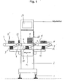
- a checkweigher shown schematically in FIG. 1, has a base frame 2 with height-adjustable feet 1 on the ground, on which a feed belt 3, a conveyor belt 4 serving as a measuring section, and a discharge belt 5 are arranged in horizontal alignment.
- the three bands 3, 4, 5 are guided in the same direction and at the same speed circumferentially over two horizontally spaced rollers, of which in each case the rollers 6, 7 and 8 are driven by electric motors 9, 10 and 11 respectively. These electric motors are controlled so that the setting of the same belt speed is ensured for all three bands 3, 4, 5.
- the number of pulses of the tachogenerator 12 occurring in a time unit thus corresponds to a transport path which has covered each of the belts 3, 4, 5 during its circulation in this time unit.
- serving as a measuring section conveyor belt 4 is supported on a fixed to the base frame 2 load cell 13.
- the latter provides with a given frequency, for example 1200 Hz, their weight corresponding weight values.
- the conveyor belt 4 serving as the measuring section 4 is fed individually with products 14 to be weighed at its input end in relation to the conveying direction by the feeding belt 3.
- Serving as a measuring section conveyor belt 4 transports her discontinued product 14 to its output side in relation to the conveying direction and transfers it there to the discharge conveyor 5.
- the latter is an only schematically indicated sorting device 16, for example in the form of a pusher, assigned by the wrong-weight Products 14 can be sorted out.
- a sensor device 17 is arranged in the form of a light barrier. This sensor device 17 detects in each case the passage of the front edge 18 and the trailing edge 19 of the product 14 when it passes in the conveying direction through the light barrier.
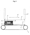
- Fig. 2 This situation is illustrated in Fig. 2, in which the arrow 20 denotes the conveying direction.
- a counter device is reset and then counted up by the pulses of the tachometer generator 12.
- the respective counter value of the counter thereby reflects the distance traveled by the front edge 18 of the product 14 since its passage through the light barrier 17 on the conveyor belt 4.
- Fig. 2 just traverses the trailing edge 19 of the product 14, the light barrier 17.
- the achieved count of the counter corresponds to the state that the product 14 rests for the first time in full length on the conveyor belt 4.
- Fig. 2 this section is illustrated by a double arrow 21. It is selected in the situation illustrated in FIG. 2 such that its beginning is determined by the position of the front edge 18 of the product 14 when its trailing edge 19 is detected by the sensor device 17.
- the end of the section 21 is located in Fig. 2 at the output end of serving as a measuring section conveyor belt 4 and is characterized by a symbolic mark 22.
- the distance between the sensor device 17 and the marking 22 along the measuring path is indicated by a double arrow 23.
- the passage of the product 14 through the selected part of the route is thus determined by the fact that the count counted up in the counter reaches the predetermined count value characterizing the beginning or the end of the selected section.
- the weight values detected by the load cell 13 during the passage of the product 14 through the selected section 21 are fed to a filter device, which derives therefrom the final weighing result by averaging.
- the weight values detected by the load cell 13 are continuously input to a buffer memory.
- the buffer memory has a capacity sufficient to store all weight values that can be generated during selectable sections. For example, it may be designed to hold 2000 weight values.
- the storage takes place in the manner of a silo storage, in which the storage contents are updated continuously in order of arrival. It thus contains at each time point in each case the last weight value detected by the weighing cell 13 and all previous weight values until the exhaustion of its capacity. When the count of the counter reaches the count corresponding to the end of the selected leg 21, the weight values accumulated during the leg 21 are read from the buffer memory and provided to the averaging filter means.
- this can be done, for example, by converting all running distances expressed by the counted counts into running times using the constant transport speed of the conveyor belt. As a result, a time base is obtained, each with the detection of the leading edge of the product 14 by the sensor device 17 starts.
- the weight values for the run-time selected for the selected sub-section 21 are transferred from the buffer memory to the filter device.
- the checkweigher has an input device with which the user can specify a partial route. For example, this is done by entering the occurring after detection of the leading edge 18 by means of the sensor device 17 total running time to reach the indicated by the mark 22 in Fig. 2 end of Operastrekke, and by entering the length of the selected section 21 corresponding residual maturity. Thereupon, the weight values for the entered partial section and for various modified settings of partial sections detected during the transport of a product 14 via the conveyor belt 4 by the load cell 13 are evaluated. The sub-segment which delivers the lowest standard deviation or variance of the detected weight values is selected as the optimum sub-segment and retained for the formation of the weighing result.
- the sections used are determined by a random number generator algorithm and can be varied again and again. It can be given a certain number of products, during which the determination of an optimal leg is performed.
- a tolerance window defined with respect to the position of the sensor device 17 can be specified for the end of the respective partial section.
- a tolerance limit can apply for the maximum length of the partial section.
- the associated mean value can change.
- These mean value fluctuations associated with the continuous optimization can be mathematically compensated in the weighing result.
- the mean value calculated from the optimum setting is corrected by a factor.
- This factor can be defined as the quotient between the mean value calculated with the partial distance preset at the beginning of the optimization procedure and the mean value calculated with the partial distance found by the optimization.
- the components serving the optimization process discussed above, in particular the filter means, the selector with its counter and the buffer memory can be realized by a microprocessor system.
- the accommodation of these components on the base frame 2 of the checkweigher is illustrated schematically in FIG. 1 by the reference numeral 24.
- This illustration also shows that the microprocessor system may have a screen showing the various processes and settings of the checkweigher.
- the filter means is realized by a separate microprocessor located in the load cell 13.
- Fig. 1 the transport direction of the products 14 is directed from left to right. It should be noted that the checkweigher may have a design which allows the reversal of the transport direction. In this case, the discharge belt 5 takes over the function of the feed belt 3 and vice versa. Accordingly, in FIG. 1, a sorting device 16 'corresponding to the sorting device 16 is indicated on the feed belt 3.
Landscapes
- Physics & Mathematics (AREA)
- General Physics & Mathematics (AREA)
- Sorting Of Articles (AREA)
- Weight Measurement For Supplying Or Discharging Of Specified Amounts Of Material (AREA)
- Control Of Conveyors (AREA)
- Sampling And Sample Adjustment (AREA)
- Coating With Molten Metal (AREA)
- Supply Of Fluid Materials To The Packaging Location (AREA)
Description
- Die Erfindung bezieht sich auf ein Verfahren zum Wiegen von Produkten, bei dem die Produkte einzeln einer Meßstrecke aufgegeben, längs der Meßstrecke transportiert, dabei in regelmäßigen Abständen Gewichtswerte erfaßt und zur Bestimmung des Wägeergebnisses aus den auf einer Teilstrecke erfaßten Gewichtswerten Mittelwerte und Varianzen gebildet werden, sowie auf eine zur Durchführung dieses Verfahrens geeignete Vorrichtung.
- Mit derartigen Verfahren werden die Produkte während ihres Transports längs der Meßstrecke dynamisch verwogen. Hierdurch läßt sich ein hoher Durchsatz erreichen, weil bei diesem dynamischen Betrieb im Unterschied zu einer statischen Waage das Einschwingen auf einen stabilen Endwert nicht abgewartet wird. Allerdings ist die Unschärfe der dynamischen Verwägung im allgemeinen um so größer, je kürzer der hierfür verfügbare Zeitabschnitt ist. Auf die Produkte wirken während ihres Transports längs der Meßstrecke zahlreiche Störungen ein, die Schwingungen hervorrufen und zu entsprechenden Schwankungen der erfaßten Gewichtswerte führen.
- Nach derartigen Verfahren arbeitende bekannte Waagen, die als Kontrollwaagen bezeichnet werden (Firmenprospekt Garvens Automation GmbH oder EP 0 507 957 A1) weisen deshalb eine Filtereinrichtung auf, die dafür vorgesehen ist, aus den bei der dynamischen Wägung jedes Produktes erfaßten Gewichtswerten einen dem wahren Gewichtswert möglichst nahekommenden Mittelwert zu bilden.
- Bei einem bekannten Verfahren der eingangs genannten Art (US-A-5 635 679) durchläuft ein Prüfgewicht die Meßstrecke in einer Anzahl von Wiederholungen. Bei jedem Durchlauf werden die Gewichtswerte an denselben vorgegebenen Meßpunkten ein und derselben vorbestimmten Teilstrecke erfaßt und für jeden Meßpunkt die Varianz bzw. die Standardabweichung für alle Durchläufe gebildet. Zur Bestimmung des endgültigen Wägeergebnisses wird derjenige Meßpunkt ausgewählt, an dem die solchermaßen bestimmte Varianz ein Minimum annimmt. Jedoch liefert die Bestimmung des Wägeergebnisses auf der Grundlage der einzigen vorbestimmten Teilstrecke nicht immer das Optimum bezüglich der Unschärfe des Wägeergebnisses.
- Der Erfindung liegt die Aufgabe zugrunde, ein Verfahren der eingangs genannten Art hinsichtlich dieser Mittelwertsbildung zu optimieren und eine zur Durchführung dieses Verfahrens geeignete Vorrichtung anzugeben.
- Erfindungsgemäß wird diese Aufgabe hinsichtlich des Verfahrens dadurch gelöst, daß aus einer Anzahl unterschiedlicher Teilstrecken, für deren jede die Varianz der darauf erfaßten Gewichtswerte gebildet wird, die die kleinste Varianz aufweisende Teilstrecke für die Bestimmung des Wägeergebnisses ausgewählt wird.
- Dem erfindungsgemäßen Verfahren liegt die Erkenntnis zugrunde, daß entgegen üblicher Erwartung die maximale Ausnutzung der längs der Meßstrecke erfaßten Gewichtswerte bei der Mittelwertsbildung nicht immer die besten Ergebnisse bezüglich der Unschärfe des Wägeergebnisses liefert. Beispielsweise neigen Produkte wie Gläser oder Dosen dazu, durch Aufprall auf die Meßstrecke Erschütterungen einzutragen, die nur langsam abklingen. Ferner können längs der Meßstrecke auch Störspitzen in den gemessenen Gewichtswerten auftreten. All dies wirkt sich in einer erhöhten Standardabweichung aus. Indem erfindungsgemäß für unterschiedliche Teilstrecken jeweils die Varianz der erfaßten Gewichtswerte bestimmt wird, kann die die kleinste Varianz aufweisende Teilstrecke aufgefunden und für die Feststellung des Wägeergebnisses ausgewählt werden. Dabei werden nur die längs der ausgewählten Teilstrecke erfaßten Gewichtswerte zur Mittelwertsbildung herangezogen und dadurch die Unschärfe des Wägeverfahrens optimiert.
- Vorteilhaft wird das erfindungsgemäße Verfahren derart ausgeführt, daß eine Teilstrecke voreingestellt und daraus die unterschiedlichen Teilstrecken durch zufällige Variationen gewonnen werden. Dies ermöglicht es besonders einfach, die Auffindung der die kleinste Varianz aufweisenden Teilstrecke zu automatisieren. Dabei kann der Benutzer durch die von ihm vorgenommene Voreinstellung seine empirische Erfahrung einbringen und insbesondere einen nach seiner Sicht wünschenswerten Rahmen für die Größe der anzuwendenden Teilstrecken vorgeben.
- Weiter ist in einer vorteilhaften Ausführungsform des erfindungsgemäßen Verfahrens vorgesehen, daß für die unterschiedlichen Teilstrecken eine untere Schranke für den Abstand zwischen ihrem Anfang und dem Anfang der Meßstrecke vorgegeben wird. Insbesondere wird diese untere Schranke derart vorgegeben, daß der Abstand zwischen dem Anfang der Meßstrecke und dem Anfang der Teilstrecke größer ist als die Länge Produkts in der Transportrichtung. Dadurch wird sichergestellt, daß nur solche Gewichtswerte in Betracht gezogen werden, bei deren Erfassung sich das Produkt in seiner vollen Länge auf der Meßstrecke befindet. Ebenso kann es vorteilhaft sein, daß für die unterschiedlichen Teilstrecken eine obere Schranke für deren Länge vorgegeben wird. Die Vorgabe einer solchen Längenbeschränkung hat den Vorteil, daß bei der Ermittlung der optimalen Teilstrecke keine Teilstrecken von so hoher Länge herangezogen werden, daß sie von vorneherein als optimal nicht in Betracht kommen. Dies schließt allerdings nicht aus, Längen zuzulassen, welche die physikalische Länge der Meßstrecke überschreiten. Sinnvoll kann dies bei der Mittelwertbildung mit Hilfe von Filtern sein, die verzögert auf den Endwert einschwingen und ausschwingen. Hierdurch kann zwar eine Verringerung des Wägeergebnisses auftreten, was sich jedoch unschwer durch geeignete Rechenlogarithmen ausgleichen läßt.
- Im Rahmen der Erfindung ist auch vorgesehen, daß die Teilstrecken mit Hilfe der konstanten Transportgeschwindigkeit der Produkte durch eine Laufzeit längs der Meßstrecke ausgedrückt werden und/oder daß die Schranken mit Hilfe der konstanten Transportgeschwindigkeit der Produkte durch eine Laufzeit längs der Meßstrecke ausgedrückt werden. Diese Maßnahmen sind insbesondere dann zweckmäßig, wenn die Gewichtswerte mit einem Wandler erfaßt werden, der die Gewichtswerte in regelmäßigen Zeitabständen, d.h. mit einer festen Frequenz liefert. Eine typische Frequenz für Wägezellen ist beispielsweise 1200 Hz. Die Darstellung mittels der jeweiligen Laufzeit ist auch im Hinblick auf die Mittelwertbildung durch einen Filter zweckmäßig, dessen Filterlänge durch eine Filterzeit ausgedrückt wird.
- Eine zur Lösung der der Erfindung zugrundeliegenden Aufgabe geeignete Vorrichtung zum Wiegen von Produkten mit einem als Meßstrecke dienenden Förderband, dem die Produkte einzeln aufgegeben und auf dem sie in einer Förderrichtung transportiert werden, einer Wägezelle, auf der das Förderband abgestützt ist und die in regelmäßigen Zeitabständen Gewichtswerte erfaßt, einer auf das Förderband ausgerichteten Sensoreinrichtung, welche jeweils das beim Transport durch ihren Erfassungsbereich hindurchtretende vordere und hintere Ende eines Produkts erfaßt, und einer Filtereinrichtung zur Bildung eines Mittelwertes aus den auf einer Teilstrecke erfaßten Gewichtswerten, ist erfindungsgemäß dadurch gekennzeichnet, daß der Filtereinrichtung eine Auswahleinrichtung zugeordnet ist, von der für eine Anzahl unterschiedlicher Teilstrecken jeweils die Varianz der erfaßten Gewichtswerte bestimmt und die die kleinste Varianz aufweisende Teilstrecke für das Wägeergebnis ausgewählt wird.
- Zweckmäßige Ausgestaltungen der erfindungsgemäßen Vorrichtung sind in den abhängigen Ansprüchen 9 und 10 angegeben.
- In der folgenden Beschreibung wird die Erfindung unter Bezugnahme auf die Zeichnung näher erläutert. Hierin zeigen:
- Fig. 1
- eine schematische Ansicht einer Kontrollwaage, und
- Fig. 2
- eine vergrößerte schematische Ansicht des auf einer Wägezelle abgestützten Förderbands dieser Kontrollwaage.
- Eine in Fig. 1 schematisch dargestellte Kontrollwaage weist einen mit höhenverstellbaren Füßen 1 auf dem Boden stehenden Grundrahmen 2 auf, an dem in horizontaler Fluchtlinie hintereinander ein Zuführband 3, ein als Meßstrecke dienendes Förderband 4 und ein Abführband 5 angeordnet sind. Die drei Bänder 3, 4, 5 sind gleichsinnig und mit gleicher Geschwindigkeit umlaufend über je zwei horizontal voneinander beabstandete Rollen geführt, von denen jeweils die Rollen 6, 7 und 8 von Elektromotoren 9, 10 bzw. 11 angetrieben sind. Diese Elektromotore sind derart geregelt, daß für alle drei Bänder 3, 4, 5 die Einstellung der selben Bandgeschwindigkeit gewährleistet ist.
- An mindestens einem der Elektromotore, im dargestellten Ausgangsbeispiel am Elektromotor 11 ist ein als Impulsgeber dienender Tachogenerator 12 vorgesehen, der eine Impulsfolge mit einer der Drehung der Abtriebswelle des Elektromotors proportionalen lmpulsfrequenz erzeugt. Die in einer Zeiteinheit auftretende Anzahl der Impulse des Tachogenerators 12 entspricht somit einer Transportstrecke, die jedes der Bänder 3, 4, 5 bei seinem Umlauf in dieser Zeiteinheit zurückgelegt hat.
- Das als Meßstrecke dienende Förderband 4 ist auf einer an dem Grundrahmen 2 festgelegten Wägezelle 13 abgestützt. Letztere liefert mit einer vorgegebenen Frequenz, beispielsweise 1200 Hz, ihrer Belastung entsprechende Gewichtswerte. Dem als Meßstrecke dienenden Förderband 4 werden zu wiegende Produkte 14 an seinem in Bezug auf die Förderrichtung eingangsseitigen Ende von dem Zuführband 3 jeweils einzeln aufgegeben. Das als Meßstrecke dienende Förderband 4 transportiert das ihr aufgegebene Produkt 14 zu seinem in Bezug auf die Förderrichtung ausgangsseitigen Ende und übergibt es dort an das Abführband 5. Letzterem ist eine nur schematisch angedeutete Sortiervorrichtung 16, beispielsweise in Form einer Schiebevorrichtung, zugeordnet, von der fehlgewichtige Produkte 14 aussortiert werden können.
- Am eingangsseitigen Ende des als Meßstrecke dienenden Förderbandes 4 ist eine Sensoreinrichtung 17 in Form einer Lichtschranke angeordnet. Diese Sensoreinrichtung 17 erfaßt jeweils den Durchtritt der Vorderkante 18 bzw. der Hinterkante 19 des Produkts 14, wenn es in der Förderrichtung durch die Lichtschranke hindurch läuft.
- Diese Situation ist in Fig. 2 verdeutlicht, in welcher der Pfeil 20 die Förderrichtung bezeichnet. Durch das den Durchgang der Vorderkante 18 anzeigende Ausgangssignal der Sensoreinrichtung 17 wird eine Zählereinrichtung zurückgesetzt und sodann von den Impulsen des Tachogenerators 12 hochgezählt. Der jeweilige Zählwert der Zähleinrichtung gibt dadurch die von der Vorderkante 18 des Produktes 14 seit ihrem Durchtritt durch die Lichtschranke 17 auf dem Förderband 4 zurückgelegte Laufstrecke wieder. In Fig. 2 durchläuft gerade die Hinterkante 19 des Produkts 14 die Lichtschranke 17. Der dabei erreichte Zählwert der Zähleinrichtung entspricht dem Zustand, daß das Produkt 14 erstmals in voller Länge auf dem Förderband 4 aufliegt.
- Zur Bildung des Wägeergebnisses aus den von der Wägezelle 13 abgegebenen Gewichtswerten werden zwei Zählwerte vorgegeben, die den Anfang und das Ende einer Teilstrecke bestimmen, die das Produkt 14 durchläuft. In Fig. 2 ist diese Teilstrecke durch einen Doppelpfeil 21 veranschaulicht. Sie ist in der in Fig. 2 veranschaulichten Situation derart gewählt, daß ihr Anfang durch die Lage der Vorderkante 18 des Produkts 14 bestimmt ist, wenn dessen Hinterkante 19 von der Sensoreinrichtung 17 erfaßt wird. Das Ende der Teilstrecke 21 liegt in Fig. 2 am ausgangsseitigen Ende des als Meßstrecke dienenden Förderbandes 4 und ist durch eine symbolische Markierung 22 gekennzeichnet. Der Abstand zwischen der Sensoreinrichtung 17 und der Markierung 22 längs der Meßstrecke ist durch einen Doppelpfeil 23 gekennzeichnet. Der Durchlauf des Produktes 14 durch die gewählte Teilstrecke ist somit dadurch bestimmt, daß der in der Zähleinrichtung hochgezählte Zählwert jeweils den den Anfang bzw. das Ende der gewählten Teilstrecke kennzeichnenden vorgegebenen Zählwert erreicht.
- Die von der Wägezelle 13 während des Durchlaufs des Produkts 14 durch die gewählte Teilstrecke 21 erfaßten Gewichtswerte werden einer Filtereinrichtung zugeführt, die daraus durch Mittelwertbildung das endgültige Wägeergebnis ableitet. Zu diesem Zweck werden die von der Wägezelle 13 erfaßten Gewichtswerte fortlaufend in einen Pufferspeicher eingegeben. Der Pufferspeicher hat ein Fassungsvermögen, das ausreicht, alle während wählbarer Teilstrecken anfallenden Gewichtswerte abzuspeichern. Beispielsweise kann er derart ausgelegt sein, daß er 2000 Gewichtswerte festhalten kann. Die Einspeicherung erfolgt nach Art eines Silospeichers, in dem der Speicherinhalt fortlaufend nach Eingangsreihenfolge aktualisiert wird. Er enthält somit zu jedem Zeitpunkt jeweils den letzten von der Wägezelle 13 erfaßten Gewichtswert und alle zurückliegenden Gewichtswerte bis zur Erschöpfung seines Fassungsvermögens. Wenn der Zählwert der Zähleinrichtung den dem Ende der gewählten Teilstrecke 21 entsprechenden Zählwert erreicht, werden die während der Teilstrecke 21 angefallenen Gewichtswerte aus dem Pufferspeicher ausgelesen und der Filtereinrichtung zur Mittelwertsbildung zur Verfügung gestellt.
- Im einzelnen kann dies beispielsweise dadurch geschehen, daß alle durch die hochgezählten Zählwerte ausgedrückten Laufstrecken mit Hilfe der konstanten Transportgeschwindigkeit des Förderbands in Laufzeiten umgerechnet werden. Dadurch wird eine Zeitbasis erhalten, die jeweils mit der Erfassung der Vorderkante des Produktes 14 durch die Sensoreinrichtung 17 startet. Wenn die dem durch die Markierung 22 gekennzeichneten Ende der Teilstrecke 21 entsprechende Laufzeit verstrichen ist, werden die Gewichtswerte für die der gewählten Teilstrecke 21 entsprechend zurückliegende Laufzeit aus dem Pufferspeicher an die Filtereinrichtung übergeben.
- Die Kontrollwaage weist eine Eingabeeinrichtung auf, mit der der Benutzer eine Teilstrecke vorgeben kann. Beispielsweise geschieht dies durch Eingabe der nach der Erfassung der Vorderkante 18 mittels der Sensoreinrichtung 17 auftretenden Gesamtlaufzeit bis zur Erreichung des durch die Markierung 22 in Fig. 2 angedeuteten Endes der Teilstrekke, und durch die Eingabe der der Länge der gewählten Teilstrecke 21 entsprechenden Restlaufzeit. Daraufhin werden die während des Transports eines Produkts 14 über das Förderband 4 von der Wägezelle 13 erfaßten Gewichtswerte für die eingegebene Teilstrekke und für verschiedene abgewandelte Einstellungen von Teilstrecken ausgewertet. Diejenige Teilstrecke, die die geringste Standardabweichung bzw. Varianz der erfaßten Gewichtswerte liefert, wird als optimale Teilstrecke ausgewählt und für die Bildung des. Wägeergebnisses beibehalten. Die verwendeten Teilstrecken werden durch einen Zufallsgenerator-Algorithmus bestimmt und können immer wieder erneut variiert werden. Es kann eine bestimmte Anzahl von Produkten vorgegeben werden, während der die Ermittlung einer optimalen Teilstrecke durchgeführt wird.
- Zur Beschleunigung der Einstellung der optimalen Teilstrecke können Beschränkungen für die verwendeten Teilstrecken vorgesehen sein. Insbesondere kann für das Ende der jeweiligen Teilstrecke ein in Bezug auf die Position der Sensoreinrichtung 17 festgelegtes Toleranzfenster vorgegeben sein. Ferner kann für die maximale Länge der Teilstrecke eine Toleranzgrenze gelten.
- Mit der Veränderung der Teilstrecken kann sich der zugehörige Mittelwert ändern. Diese mit der fortlaufenden Optimierung verbundenen Mittelwertschwankungen können im Wägeergebnis rechnerisch ausgeglichen werden. Hierzu wird der aus der optimalen Einstellung berechnete Mittelwert mit einem Faktor korrigiert. Dieser Faktor kann als Quotient zwischen dem mit der zu Beginn des Optimierungsvorgangs voreingestellten Teilstrecke errechneten Mittelwert und dem mit der durch die Optimierung gefundenen Teilstrecke berechneten Mittelwert definiert werden.
- Die dem vorstehend erörterten Optimierungsvorgang dienenden Komponenten, insbesondere die Filtereinrichtung, die Auswahleinrichtung mit ihrer Zähleinrichtung und der Pufferspeicher können durch ein Mikroprozessorsystem verwirklicht werden. Die Unterbringung dieser Komponenten am Grundrahmen 2 der Kontrollwaage ist in Fig. 1 schematisch unter dem Bezugszeichen 24 veranschaulicht. Diese Darstellung läßt auch erkennen, daß das Mikroprozessorsystem einen Bildschirm aufweisen kann, auf dem die verschiedenen Vorgänge und Einstellungen der Kontrollwaage dargestellt werden. Vorzugsweise wird jedoch die Filtereinrichtung durch einen getrennten Mikroprozessor verwirklicht, der in der Wägezelle 13 angeordnet ist.
- In Fig. 1 ist die Transportrichtung der Produkte 14 von links nach rechts gerichtet. Es ist darauf hinzuweisen, daß die Kontrollwaage eine Ausbildung aufweisen kann, welche die Umkehr der Transportrichtung ermöglicht. In diesem Fall übernimmt das Abführband 5 die Funktion des Zuführbands 3 und umgekehrt. Dementsprechend ist in Fig. 1 an dem Zuführband 3 eine der Sortiervorrichtung 16 entsprechende Sortiervorrichtung 16' angedeutet.
-
- 1
- Füße
- 2
- Grundrahmen
- 3
- Zuführband
- 4
- Förderband
- 5
- Abführband
- 6,7,8
- Rollen
- 9, 10, 11
- Elektromotore
- 12
- Tachogenerator
- 13
- Wägezelle
- 14
- Produkt
- 16, 16'
- Sortiervorrichtung
- 17
- Sensoreinrichtung
- 18
- Vorderkante
- 19
- Hinterkante
- 20
- Förderrichtung
- 21
- Doppelpfeil
- 22
- Markierung
- 23
- Doppelpfeil
- 24
- Mikroprozessorsystem
Claims (10)
- Verfahren zum Wiegen von Produkten, bei dem die Produkte einzeln einer Meßstrecke aufgegeben, längs der Meßstrecke transportiert, dabei in regelmäßigen Abständen Gewichtswerte erfaßt und zur Bestimmung des Wägeergebnisses aus den auf einer Teilstrecke erfaßten Gewichtswerten Mittelwerte und Varianzen gebildet werden, dadurch gekennzeichnet, daß aus einer Anzahl unterschiedlicher Teilstrecken, für deren jede die Varianz der darauf erfaßten Gewichtswerte gebildet wird, die die kleinste Varianz aufweisende Teilstrecke für die Bestimmung des Wägeergebnisses ausgewählt wird.
- Verfahren nach Anspruch 1, dadurch gekennzeichnet, daß eine Teilstrecke voreingestellt und daraus die unterschiedlichen Teilstrecken durch zufällige Variationen gewonnen werden.
- Verfahren nach Anspruch 1 oder 2, dadurch gekennzeichnet, daß für die unterschiedlichen Teilstrecken eine untere Schranke für den Abstand zwischen ihrem Anfang und dem Anfang der Meßstrecke vorgegeben wird.
- Verfahren nach einem der Ansprüche 1 bis 3, dadurch gekennzeichnet, daß für die unterschiedlichen Teilstrecken eine obere Schranke für deren Länge vorgegeben wird.
- Verfahren nach einem der Ansprüche 1 bis 4, dadurch gekennzeichnet, daß die Teilstrecken mit Hilfe der konstanten Transportgeschwindigkeit der Produkte durch eine Laufzeit längs der Meßstrecke ausgedrückt werden.
- Verfahren nach Anspruch 3 oder 4, dadurch gekennzeichnet, daß die Schranken mit Hilfe der konstanten Transportgeschwindigkeit der Produkte durch eine Laufzeit längs der Meßstrecke ausgedrückt werden.
- Vorrichtung zum Wiegen von Produkten mit einem als Meßstrecke dienenden Förderband (4), dem die Produkte einzeln aufgegeben und auf dem sie in einer Förderrichtung (20) transportiert werden, einer Wägezelle (13), auf der das Förderband (4) abgestützt ist und die in regelmäßigen Zeitabständen Gewichtswerte erfaßt, einer auf das Förderband (4) ausgerichteten Sensoreinrichtung (17), welche jeweils das beim Transport durch ihren Erfassungsbereich hindurchtretende vordere (18) und hintere (19) Ende eines Produkts (14) erfaßt, einer Filtereinrichtung und einer ihr zugeordneten Auswahleinrichtung zur Bestimmung des Wägeergebnisses aufgrund von aus auf einer Teilstrecke erfaßten Gewichtswerten gebildeten Mittelwerten und Varianzen, dadurch gekennzeichnet, daß von der Auswahleinrichtung aus einer Anzahl unterschiedlicher Teilstrecken, für deren jede jeweils die Varianz der darauf erfaßten Gewichtswerte gebildet wird, die die kleinste Varianz aufweisende Teilstrecke für die Bestimmung des Wägeergebnisses ausgewählt wird.
- Vorrichtung nach Anspruch 7, dadurch gekennzeichnet, daß dem Förderband (4) ein eine zu dessen Transportbewegung proportionale Impulsfolge liefernder Impulsgeber (12) zugeordnet ist, sowie eine zur Zählung der Impulse der Impulsfolge dienende Zähleinrichtung, die durch das das vordere Ende (18) eines Produkts (14) erfassende Ausgangssignal der Sensoreinrichtung (17) zurückgesetzt und von den eingehenden Impulsen hochgezählt wird, wobei jeweils der Anfang und das Ende jeder Teilstrecke durch entsprechende Zählwerte der Zähleinrichtung bestimmt wird.
- Vorrichtung nach Anspruch 8, dadurch gekennzeichnet, daß der den Anfang jeder Teilstrecke bestimmende Zählwert der bei der Erfassung des hinteren Endes (19) des Produktes (14) durch die Sensoreinrichtung (17) hochgezählte Zählwert ist.
- Vorrichtung nach einem der Ansprüche 7 bis 9, dadurch gekennzeichnet, daß ein zur Zwischenspeicherung einer Reihe von jeweils bis zum gegenwärtigen Zeitpunkt erfaßter Gewichtswerte dienender Pufferspeicher vorgesehen ist, aus dem die der gewählten Teilstrecke entsprechenden Gewichtswerte der Filtereinrichtung zuführbar sind.
Priority Applications (1)
| Application Number | Priority Date | Filing Date | Title |
|---|---|---|---|
| PL04739229T PL1625367T3 (pl) | 2003-05-19 | 2004-05-17 | Sposób i urządzenie do ważenia produktów |
Applications Claiming Priority (2)
| Application Number | Priority Date | Filing Date | Title |
|---|---|---|---|
| DE10322504A DE10322504A1 (de) | 2003-05-19 | 2003-05-19 | Verfahren und Vorrichtung zum Wiegen von Produkten |
| PCT/EP2004/005299 WO2004102135A1 (de) | 2003-05-19 | 2004-05-17 | Verfahren und vorrichtung zum wiegen von produkten |
Publications (2)
| Publication Number | Publication Date |
|---|---|
| EP1625367A1 EP1625367A1 (de) | 2006-02-15 |
| EP1625367B1 true EP1625367B1 (de) | 2006-10-04 |
Family
ID=33440967
Family Applications (1)
| Application Number | Title | Priority Date | Filing Date |
|---|---|---|---|
| EP04739229A Expired - Lifetime EP1625367B1 (de) | 2003-05-19 | 2004-05-17 | Verfahren und vorrichtung zum wiegen von produkten |
Country Status (9)
| Country | Link |
|---|---|
| US (1) | US7405368B2 (de) |
| EP (1) | EP1625367B1 (de) |
| AT (1) | ATE341750T1 (de) |
| CA (1) | CA2540352C (de) |
| DE (2) | DE10322504A1 (de) |
| DK (1) | DK1625367T3 (de) |
| ES (1) | ES2273265T3 (de) |
| PL (1) | PL1625367T3 (de) |
| WO (1) | WO2004102135A1 (de) |
Cited By (2)
| Publication number | Priority date | Publication date | Assignee | Title |
|---|---|---|---|---|
| DE102007013333A1 (de) | 2007-03-20 | 2008-09-25 | Bizerba Gmbh & Co. Kg | Verfahren zur Parametrierung und zum Betrieb von Waagen |
| DE102024131475A1 (de) | 2024-10-29 | 2026-04-30 | Multivac Marking & Inspection Gmbh & Co. Kg | Wiegevorrichtung und Verfahren zum Wiegen von Produkten |
Families Citing this family (25)
| Publication number | Priority date | Publication date | Assignee | Title |
|---|---|---|---|---|
| US7626130B2 (en) | 2005-02-09 | 2009-12-01 | Sartorius Mechatronics C & D Gmbh & Co. Kg | Check weigher with hollow body and mounting flange |
| DE102005007866A1 (de) * | 2005-02-21 | 2006-08-24 | Mettler-Toledo Garvens Gmbh | Verfahren und Vorrichtung zum Wiegen von Produkten |
| US7668692B2 (en) * | 2005-10-11 | 2010-02-23 | Tatom Frank B | Method for weighing vehicles crossing a bridge |
| DE102006052486A1 (de) * | 2006-11-07 | 2008-05-08 | Robert Bosch Gmbh | Steuerung für eine Waage |
| DE102007025580A1 (de) | 2007-06-01 | 2008-12-04 | Mettler-Toledo Garvens Gmbh | Verfahren und Vorrichtung zum Wiegen von Produkten |
| DE102007040301B4 (de) | 2007-08-24 | 2013-07-18 | Sartorius Weighing Technology Gmbh | Verfahren und Vorrichtung zur dynamischen Kontrollwägung |
| DE102007040300B4 (de) | 2007-08-24 | 2013-07-11 | Sartorius Weighing Technology Gmbh | Verfahren und Vorrichtung zur dynamischen Kontrollwägung |
| US8153911B2 (en) | 2008-10-01 | 2012-04-10 | Raf Technology, Inc. | Dynamically weighing mail pieces in real time within an automated destination bar code sorter machine by temporarily accelerating the mail piece and capturing resulting closed loop motor torque sample data |
| US9018544B2 (en) * | 2007-09-13 | 2015-04-28 | Raf Technology, Inc. | In-line conveyor scale with a primary first motor to provide constant torque, a secondary servo motor to provide fine-grained variable torque in response to a closed loop torque sensor, and a processor to assertain weight of an item conveved based on the closed loop servo motor response |
| US8481871B2 (en) | 2007-09-13 | 2013-07-09 | Raf Technology, Inc. | Dynamic thickness adaptation for an in-line scale |
| US8466380B2 (en) * | 2008-11-27 | 2013-06-18 | Teraoka Seiko Co., Ltd. | Apparatus and method for measuring articles including conveyor-weighers supported on weighing unit |
| DE102010009431A1 (de) * | 2010-02-24 | 2011-08-25 | Francotyp-Postalia GmbH, 16547 | Schnelle dynamische Waage und Verfahren zur Steuerung einer schnellen dynamischen Waage |
| DE102010019742A1 (de) | 2010-05-07 | 2011-11-10 | Bizerba Gmbh & Co. Kg | Wäge- und Sortiervorrichtung |
| JP5961063B2 (ja) * | 2012-07-27 | 2016-08-02 | アンリツインフィビス株式会社 | 計量装置 |
| US9091585B2 (en) | 2013-02-08 | 2015-07-28 | Raf Technology, Inc. | Smart phone scale that uses the built-in barometric pressure sensor or orientation sensors to calculate weight |
| US9564849B2 (en) | 2013-05-06 | 2017-02-07 | Raf Technology, Inc. | Scale for weighing flowing granular materials |
| JP6244109B2 (ja) * | 2013-05-31 | 2017-12-06 | 東京応化工業株式会社 | レジスト組成物、化合物、高分子化合物及びレジストパターン形成方法 |
| US9863801B2 (en) | 2014-05-01 | 2018-01-09 | Velox Robotics, Llc | High speed robotic weighing system |
| JP6495725B2 (ja) * | 2015-04-16 | 2019-04-03 | アンリツインフィビス株式会社 | 計量装置 |
| CN105573284B (zh) * | 2016-02-22 | 2018-12-14 | 郑州纽路普科技有限公司 | 自动配料机器人 |
| DE102016117966B4 (de) * | 2016-09-23 | 2025-04-30 | Espera-Werke Gmbh | Wägevorrichtung und Verfahren zum Wiegen eines Produkts |
| US10753786B2 (en) | 2018-06-21 | 2020-08-25 | Mettler-Toledo, LLC | Weigh-in-motion system and method with weigh time optimization |
| US10745039B1 (en) * | 2019-08-19 | 2020-08-18 | Sbot Technologies, Inc. | Accurate weight measurement system and method operable with a movable device |
| DE102020104645A1 (de) | 2020-02-21 | 2021-08-26 | Minebea Intec Aachen GmbH & Co. KG | Kontrollwaage |
| US20220058908A1 (en) | 2020-08-19 | 2022-02-24 | Pepsico, Inc. | Product delivery mechanism for a vending machine |
Family Cites Families (13)
| Publication number | Priority date | Publication date | Assignee | Title |
|---|---|---|---|---|
| US3063635A (en) * | 1959-11-02 | 1962-11-13 | Epsco Inc | System for measuring the weight of dynamic loads |
| US3276525A (en) * | 1964-06-15 | 1966-10-04 | Canadian Nat Railway Co | Method and apparatus for dynamically weighing objects in motion |
| US4231439A (en) * | 1979-04-23 | 1980-11-04 | Franklin Electric Subsidiaries, Inc. | Automatic check weigher |
| JPH0621814B2 (ja) * | 1986-05-29 | 1994-03-23 | 大和製衡株式会社 | 計重装置の計重信号の濾波方法及び装置 |
| DE3823191A1 (de) * | 1988-07-08 | 1990-01-11 | Pfister Gmbh | Foerderband- bzw. dosierwaage und verfahren zu deren betrieb |
| GB2228092A (en) * | 1989-02-13 | 1990-08-15 | Hitech Electrocontrols Ltd | Reducing random errors in transducer measurement |
| DE3933424C1 (de) * | 1989-10-06 | 1991-04-18 | Carl Schenck Ag, 6100 Darmstadt, De | |
| EP0507957B1 (de) * | 1990-10-30 | 1996-05-08 | ISHIDA CO., Ltd. | Kontrollwaagen mit Längenberücksichtigung |
| US5300736A (en) * | 1992-03-12 | 1994-04-05 | Hi-Speed Checkweigher Co., Inc. | Adaptive timing in-motion checkweigher |
| GB2287541B (en) * | 1994-03-07 | 1998-04-15 | Yamato Scale Co Ltd | Device and method for determining weighing conditions of dynamic weighing device |
| US5814772A (en) * | 1995-01-11 | 1998-09-29 | Ishida Co., Ltd. | Weighing apparatus with weight detecting conveyor |
| JP2943731B2 (ja) * | 1996-10-28 | 1999-08-30 | トヨタ自動車株式会社 | 溶接装置 |
| AU2543999A (en) * | 1998-01-20 | 1999-08-02 | Marel Hf. | Method and apparatus for weighing |
-
2003
- 2003-05-19 DE DE10322504A patent/DE10322504A1/de not_active Withdrawn
-
2004
- 2004-05-17 US US10/557,279 patent/US7405368B2/en not_active Expired - Fee Related
- 2004-05-17 DE DE502004001690T patent/DE502004001690D1/de not_active Expired - Lifetime
- 2004-05-17 ES ES04739229T patent/ES2273265T3/es not_active Expired - Lifetime
- 2004-05-17 CA CA002540352A patent/CA2540352C/en not_active Expired - Fee Related
- 2004-05-17 PL PL04739229T patent/PL1625367T3/pl unknown
- 2004-05-17 AT AT04739229T patent/ATE341750T1/de active
- 2004-05-17 EP EP04739229A patent/EP1625367B1/de not_active Expired - Lifetime
- 2004-05-17 WO PCT/EP2004/005299 patent/WO2004102135A1/de not_active Ceased
- 2004-05-17 DK DK04739229T patent/DK1625367T3/da active
Cited By (2)
| Publication number | Priority date | Publication date | Assignee | Title |
|---|---|---|---|---|
| DE102007013333A1 (de) | 2007-03-20 | 2008-09-25 | Bizerba Gmbh & Co. Kg | Verfahren zur Parametrierung und zum Betrieb von Waagen |
| DE102024131475A1 (de) | 2024-10-29 | 2026-04-30 | Multivac Marking & Inspection Gmbh & Co. Kg | Wiegevorrichtung und Verfahren zum Wiegen von Produkten |
Also Published As
| Publication number | Publication date |
|---|---|
| DE10322504A1 (de) | 2004-12-09 |
| PL1625367T3 (pl) | 2007-02-28 |
| DE502004001690D1 (de) | 2006-11-16 |
| US20070181349A1 (en) | 2007-08-09 |
| CA2540352A1 (en) | 2004-11-25 |
| ES2273265T3 (es) | 2007-05-01 |
| HK1092521A1 (en) | 2007-02-09 |
| US7405368B2 (en) | 2008-07-29 |
| DK1625367T3 (da) | 2007-02-05 |
| CA2540352C (en) | 2009-07-21 |
| WO2004102135A1 (de) | 2004-11-25 |
| ATE341750T1 (de) | 2006-10-15 |
| EP1625367A1 (de) | 2006-02-15 |
Similar Documents
| Publication | Publication Date | Title |
|---|---|---|
| EP1625367B1 (de) | Verfahren und vorrichtung zum wiegen von produkten | |
| EP0953142B1 (de) | Bandwaage | |
| DE3111811C2 (de) | Wägemaschine | |
| EP0421165B1 (de) | Verfahren zum Tarieren einer Dosierbandwaage | |
| DE102007040301B4 (de) | Verfahren und Vorrichtung zur dynamischen Kontrollwägung | |
| DE4323305B4 (de) | Verfahren und Vorrichtung zur Korrektur der Basisdrift eines Sensors | |
| DE19820058B4 (de) | Verfahren zum Zerteilen von Produktlaiben sowie Vorrichtung zu seiner Durchführung | |
| DE2319721C2 (de) | Vorrichtung zum Trennen einer Mischung von Materialien in zwei Materialgruppen | |
| DE69411473T2 (de) | Kombinatorische Messsysteme und -verfahren | |
| DE3129389C2 (de) | ||
| DE3208019C2 (de) | Vorrichtung zum Wiegen von Früchten und zum Zusammenstellen einer Menge aus diesen Früchten | |
| DE102007040300B4 (de) | Verfahren und Vorrichtung zur dynamischen Kontrollwägung | |
| DE19609431A1 (de) | Verfahren zum Wägen und Etikettieren von Warenpackungen und Vorrichtung zur Durchführung des Verfahrens | |
| DE4014130A1 (de) | Vorrichtung zum behandeln von kartenfoermigen gegenstaenden | |
| CH685708A5 (de) | Verfahren und Vorrichtung zum Abtragen und Mischen von Textilfasern, z.B. Baumwolle, Chemiefasern und dgl. | |
| EP1925921A2 (de) | Verfahren und Vorrichtung zur Bestimmung der Masse von Stückgut auf einer Fördereinrichtung | |
| DE3313030C2 (de) | ||
| AT396209B (de) | Arbeitsverfahren zur weiterverarbeitung von aus einer walzstrasse kontinuierlich herangefoerderten, zu gruppen gesammelten walzstaeben und trenneinrichtung zur durchfuehrung dieses arbeitsverfahrens | |
| EP3415463B1 (de) | Anordnen von abschnitten einer federschlange für die herstellung eines federkerns | |
| DE10345613B4 (de) | Verfahren und Vorrichtung zum Klassieren einer Menge von Kartoffeln | |
| DE3119990C2 (de) | ||
| DE1549191B1 (de) | Verfahren und Vorrichtung zum Abwaegen jeweils gleicher Schuettgutmengen | |
| EP2150784A1 (de) | Verfahren und vorrichtung zum wiegen von produkten | |
| DE3425082A1 (de) | Fuellmaschine mit mehreren fuellstutzen und einem foerderer zum abtransport der gefuellten saecke dem eine kontrollwaage zugeordnet ist | |
| EP0027097A2 (de) | Einrichtung zum Fördern, und insbesondere Dosieren, eines faserigen Gutes |
Legal Events
| Date | Code | Title | Description |
|---|---|---|---|
| PUAI | Public reference made under article 153(3) epc to a published international application that has entered the european phase |
Free format text: ORIGINAL CODE: 0009012 |
|
| 17P | Request for examination filed |
Effective date: 20051114 |
|
| AK | Designated contracting states |
Kind code of ref document: A1 Designated state(s): AT BE BG CH CY CZ DE DK EE ES FI FR GB GR HU IE IT LI LU MC NL PL PT RO SE SI SK TR |
|
| GRAP | Despatch of communication of intention to grant a patent |
Free format text: ORIGINAL CODE: EPIDOSNIGR1 |
|
| RAP1 | Party data changed (applicant data changed or rights of an application transferred) |
Owner name: METTLER-TOLEDO GARVENS GMBH |
|
| GRAS | Grant fee paid |
Free format text: ORIGINAL CODE: EPIDOSNIGR3 |
|
| DAX | Request for extension of the european patent (deleted) | ||
| GRAA | (expected) grant |
Free format text: ORIGINAL CODE: 0009210 |
|
| AK | Designated contracting states |
Kind code of ref document: B1 Designated state(s): AT BE BG CH CY CZ DE DK EE ES FI FR GB GR HU IE IT LI LU MC NL PL PT RO SE SI SK TR |
|
| PG25 | Lapsed in a contracting state [announced via postgrant information from national office to epo] |
Ref country code: IT Free format text: LAPSE BECAUSE OF FAILURE TO SUBMIT A TRANSLATION OF THE DESCRIPTION OR TO PAY THE FEE WITHIN THE PRESCRIBED TIME-LIMIT;WARNING: LAPSES OF ITALIAN PATENTS WITH EFFECTIVE DATE BEFORE 2007 MAY HAVE OCCURRED AT ANY TIME BEFORE 2007. THE CORRECT EFFECTIVE DATE MAY BE DIFFERENT FROM THE ONE RECORDED. Effective date: 20061004 Ref country code: RO Free format text: LAPSE BECAUSE OF FAILURE TO SUBMIT A TRANSLATION OF THE DESCRIPTION OR TO PAY THE FEE WITHIN THE PRESCRIBED TIME-LIMIT Effective date: 20061004 Ref country code: SI Free format text: LAPSE BECAUSE OF FAILURE TO SUBMIT A TRANSLATION OF THE DESCRIPTION OR TO PAY THE FEE WITHIN THE PRESCRIBED TIME-LIMIT Effective date: 20061004 Ref country code: IE Free format text: LAPSE BECAUSE OF FAILURE TO SUBMIT A TRANSLATION OF THE DESCRIPTION OR TO PAY THE FEE WITHIN THE PRESCRIBED TIME-LIMIT Effective date: 20061004 Ref country code: FI Free format text: LAPSE BECAUSE OF FAILURE TO SUBMIT A TRANSLATION OF THE DESCRIPTION OR TO PAY THE FEE WITHIN THE PRESCRIBED TIME-LIMIT Effective date: 20061004 Ref country code: CZ Free format text: LAPSE BECAUSE OF FAILURE TO SUBMIT A TRANSLATION OF THE DESCRIPTION OR TO PAY THE FEE WITHIN THE PRESCRIBED TIME-LIMIT Effective date: 20061004 Ref country code: SK Free format text: LAPSE BECAUSE OF FAILURE TO SUBMIT A TRANSLATION OF THE DESCRIPTION OR TO PAY THE FEE WITHIN THE PRESCRIBED TIME-LIMIT Effective date: 20061004 |
|
| REG | Reference to a national code |
Ref country code: GB Ref legal event code: FG4D Free format text: NOT ENGLISH |
|
| REG | Reference to a national code |
Ref country code: CH Ref legal event code: EP |
|
| REG | Reference to a national code |
Ref country code: IE Ref legal event code: FG4D Free format text: LANGUAGE OF EP DOCUMENT: GERMAN |
|
| REF | Corresponds to: |
Ref document number: 502004001690 Country of ref document: DE Date of ref document: 20061116 Kind code of ref document: P |
|
| PG25 | Lapsed in a contracting state [announced via postgrant information from national office to epo] |
Ref country code: BG Free format text: LAPSE BECAUSE OF FAILURE TO SUBMIT A TRANSLATION OF THE DESCRIPTION OR TO PAY THE FEE WITHIN THE PRESCRIBED TIME-LIMIT Effective date: 20070104 |
|
| GBT | Gb: translation of ep patent filed (gb section 77(6)(a)/1977) |
Effective date: 20061214 |
|
| REG | Reference to a national code |
Ref country code: SE Ref legal event code: TRGR |
|
| REG | Reference to a national code |
Ref country code: DK Ref legal event code: T3 |
|
| REG | Reference to a national code |
Ref country code: HK Ref legal event code: DE Ref document number: 1092521 Country of ref document: HK |
|
| REG | Reference to a national code |
Ref country code: PL Ref legal event code: T3 |
|
| PG25 | Lapsed in a contracting state [announced via postgrant information from national office to epo] |
Ref country code: PT Free format text: LAPSE BECAUSE OF FAILURE TO SUBMIT A TRANSLATION OF THE DESCRIPTION OR TO PAY THE FEE WITHIN THE PRESCRIBED TIME-LIMIT Effective date: 20070316 |
|
| REG | Reference to a national code |
Ref country code: HU Ref legal event code: AG4A Ref document number: E001092 Country of ref document: HU |
|
| ET | Fr: translation filed | ||
| REG | Reference to a national code |
Ref country code: ES Ref legal event code: FG2A Ref document number: 2273265 Country of ref document: ES Kind code of ref document: T3 |
|
| REG | Reference to a national code |
Ref country code: IE Ref legal event code: FD4D |
|
| REG | Reference to a national code |
Ref country code: HK Ref legal event code: GR Ref document number: 1092521 Country of ref document: HK |
|
| PLBE | No opposition filed within time limit |
Free format text: ORIGINAL CODE: 0009261 |
|
| STAA | Information on the status of an ep patent application or granted ep patent |
Free format text: STATUS: NO OPPOSITION FILED WITHIN TIME LIMIT |
|
| 26N | No opposition filed |
Effective date: 20070705 |
|
| PG25 | Lapsed in a contracting state [announced via postgrant information from national office to epo] |
Ref country code: MC Free format text: LAPSE BECAUSE OF NON-PAYMENT OF DUE FEES Effective date: 20070531 |
|
| PG25 | Lapsed in a contracting state [announced via postgrant information from national office to epo] |
Ref country code: GR Free format text: LAPSE BECAUSE OF FAILURE TO SUBMIT A TRANSLATION OF THE DESCRIPTION OR TO PAY THE FEE WITHIN THE PRESCRIBED TIME-LIMIT Effective date: 20070105 |
|
| PG25 | Lapsed in a contracting state [announced via postgrant information from national office to epo] |
Ref country code: EE Free format text: LAPSE BECAUSE OF FAILURE TO SUBMIT A TRANSLATION OF THE DESCRIPTION OR TO PAY THE FEE WITHIN THE PRESCRIBED TIME-LIMIT Effective date: 20061004 |
|
| PGRI | Patent reinstated in contracting state [announced from national office to epo] |
Ref country code: IT Effective date: 20080601 |
|
| PG25 | Lapsed in a contracting state [announced via postgrant information from national office to epo] |
Ref country code: LU Free format text: LAPSE BECAUSE OF NON-PAYMENT OF DUE FEES Effective date: 20070517 Ref country code: CY Free format text: LAPSE BECAUSE OF FAILURE TO SUBMIT A TRANSLATION OF THE DESCRIPTION OR TO PAY THE FEE WITHIN THE PRESCRIBED TIME-LIMIT Effective date: 20061004 |
|
| PGFP | Annual fee paid to national office [announced via postgrant information from national office to epo] |
Ref country code: TR Payment date: 20090430 Year of fee payment: 6 |
|
| PGFP | Annual fee paid to national office [announced via postgrant information from national office to epo] |
Ref country code: HU Payment date: 20090608 Year of fee payment: 6 |
|
| PG25 | Lapsed in a contracting state [announced via postgrant information from national office to epo] |
Ref country code: HU Free format text: LAPSE BECAUSE OF NON-PAYMENT OF DUE FEES Effective date: 20100518 |
|
| PGFP | Annual fee paid to national office [announced via postgrant information from national office to epo] |
Ref country code: DK Payment date: 20120426 Year of fee payment: 9 |
|
| PGFP | Annual fee paid to national office [announced via postgrant information from national office to epo] |
Ref country code: PL Payment date: 20120418 Year of fee payment: 9 Ref country code: SE Payment date: 20120507 Year of fee payment: 9 |
|
| PG25 | Lapsed in a contracting state [announced via postgrant information from national office to epo] |
Ref country code: TR Free format text: LAPSE BECAUSE OF NON-PAYMENT OF DUE FEES Effective date: 20100517 |
|
| PGFP | Annual fee paid to national office [announced via postgrant information from national office to epo] |
Ref country code: AT Payment date: 20120426 Year of fee payment: 9 |
|
| REG | Reference to a national code |
Ref country code: SE Ref legal event code: EUG |
|
| REG | Reference to a national code |
Ref country code: AT Ref legal event code: MM01 Ref document number: 341750 Country of ref document: AT Kind code of ref document: T Effective date: 20130531 |
|
| PG25 | Lapsed in a contracting state [announced via postgrant information from national office to epo] |
Ref country code: SE Free format text: LAPSE BECAUSE OF NON-PAYMENT OF DUE FEES Effective date: 20130518 Ref country code: AT Free format text: LAPSE BECAUSE OF NON-PAYMENT OF DUE FEES Effective date: 20130531 |
|
| REG | Reference to a national code |
Ref country code: DK Ref legal event code: EBP Effective date: 20130531 |
|
| PG25 | Lapsed in a contracting state [announced via postgrant information from national office to epo] |
Ref country code: DK Free format text: LAPSE BECAUSE OF NON-PAYMENT OF DUE FEES Effective date: 20130531 |
|
| PG25 | Lapsed in a contracting state [announced via postgrant information from national office to epo] |
Ref country code: PL Free format text: LAPSE BECAUSE OF NON-PAYMENT OF DUE FEES Effective date: 20130517 |
|
| REG | Reference to a national code |
Ref country code: PL Ref legal event code: LAPE |
|
| REG | Reference to a national code |
Ref country code: FR Ref legal event code: PLFP Year of fee payment: 12 |
|
| PGFP | Annual fee paid to national office [announced via postgrant information from national office to epo] |
Ref country code: ES Payment date: 20150512 Year of fee payment: 12 Ref country code: DE Payment date: 20150601 Year of fee payment: 12 Ref country code: CH Payment date: 20150428 Year of fee payment: 12 Ref country code: GB Payment date: 20150424 Year of fee payment: 12 |
|
| PGFP | Annual fee paid to national office [announced via postgrant information from national office to epo] |
Ref country code: BE Payment date: 20150511 Year of fee payment: 12 Ref country code: FR Payment date: 20150424 Year of fee payment: 12 Ref country code: NL Payment date: 20150512 Year of fee payment: 12 Ref country code: IT Payment date: 20150514 Year of fee payment: 12 |
|
| PG25 | Lapsed in a contracting state [announced via postgrant information from national office to epo] |
Ref country code: BE Free format text: LAPSE BECAUSE OF NON-PAYMENT OF DUE FEES Effective date: 20160531 |
|
| REG | Reference to a national code |
Ref country code: DE Ref legal event code: R119 Ref document number: 502004001690 Country of ref document: DE |
|
| REG | Reference to a national code |
Ref country code: CH Ref legal event code: PL |
|
| REG | Reference to a national code |
Ref country code: NL Ref legal event code: MM Effective date: 20160601 |
|
| GBPC | Gb: european patent ceased through non-payment of renewal fee |
Effective date: 20160517 |
|
| PG25 | Lapsed in a contracting state [announced via postgrant information from national office to epo] |
Ref country code: LI Free format text: LAPSE BECAUSE OF NON-PAYMENT OF DUE FEES Effective date: 20160531 Ref country code: CH Free format text: LAPSE BECAUSE OF NON-PAYMENT OF DUE FEES Effective date: 20160531 |
|
| PG25 | Lapsed in a contracting state [announced via postgrant information from national office to epo] |
Ref country code: NL Free format text: LAPSE BECAUSE OF NON-PAYMENT OF DUE FEES Effective date: 20160601 Ref country code: IT Free format text: LAPSE BECAUSE OF FAILURE TO SUBMIT A TRANSLATION OF THE DESCRIPTION OR TO PAY THE FEE WITHIN THE PRESCRIBED TIME-LIMIT Effective date: 20160517 |
|
| REG | Reference to a national code |
Ref country code: FR Ref legal event code: ST Effective date: 20170131 |
|
| PG25 | Lapsed in a contracting state [announced via postgrant information from national office to epo] |
Ref country code: DE Free format text: LAPSE BECAUSE OF NON-PAYMENT OF DUE FEES Effective date: 20161201 Ref country code: FR Free format text: LAPSE BECAUSE OF NON-PAYMENT OF DUE FEES Effective date: 20160531 |
|
| PG25 | Lapsed in a contracting state [announced via postgrant information from national office to epo] |
Ref country code: GB Free format text: LAPSE BECAUSE OF NON-PAYMENT OF DUE FEES Effective date: 20160517 |
|
| PG25 | Lapsed in a contracting state [announced via postgrant information from national office to epo] |
Ref country code: ES Free format text: LAPSE BECAUSE OF NON-PAYMENT OF DUE FEES Effective date: 20160518 |
|
| REG | Reference to a national code |
Ref country code: ES Ref legal event code: FD2A Effective date: 20181204 |