EP1625954A2 - Reifendemontiervorrichtung mit einem einzigen Multifunktionswerkzeug - Google Patents
Reifendemontiervorrichtung mit einem einzigen Multifunktionswerkzeug Download PDFInfo
- Publication number
- EP1625954A2 EP1625954A2 EP05076693A EP05076693A EP1625954A2 EP 1625954 A2 EP1625954 A2 EP 1625954A2 EP 05076693 A EP05076693 A EP 05076693A EP 05076693 A EP05076693 A EP 05076693A EP 1625954 A2 EP1625954 A2 EP 1625954A2
- Authority
- EP
- European Patent Office
- Prior art keywords
- tyre
- bead
- removal machine
- tool
- engaging member
- Prior art date
- Legal status (The legal status is an assumption and is not a legal conclusion. Google has not performed a legal analysis and makes no representation as to the accuracy of the status listed.)
- Granted
Links
- 239000011324 bead Substances 0.000 description 26
- 239000003638 chemical reducing agent Substances 0.000 description 3
- 238000004519 manufacturing process Methods 0.000 description 3
- 239000002184 metal Substances 0.000 description 2
- OKTJSMMVPCPJKN-UHFFFAOYSA-N Carbon Chemical compound [C] OKTJSMMVPCPJKN-UHFFFAOYSA-N 0.000 description 1
- 239000004677 Nylon Substances 0.000 description 1
- 230000001419 dependent effect Effects 0.000 description 1
- 239000000428 dust Substances 0.000 description 1
- 239000000284 extract Substances 0.000 description 1
- 238000000605 extraction Methods 0.000 description 1
- 239000012530 fluid Substances 0.000 description 1
- 229910002804 graphite Inorganic materials 0.000 description 1
- 239000010439 graphite Substances 0.000 description 1
- 230000004886 head movement Effects 0.000 description 1
- 239000000463 material Substances 0.000 description 1
- 229920001778 nylon Polymers 0.000 description 1
- 125000006850 spacer group Chemical group 0.000 description 1
Images


Classifications
-
- B—PERFORMING OPERATIONS; TRANSPORTING
- B60—VEHICLES IN GENERAL
- B60C—VEHICLE TYRES; TYRE INFLATION; TYRE CHANGING; CONNECTING VALVES TO INFLATABLE ELASTIC BODIES IN GENERAL; DEVICES OR ARRANGEMENTS RELATED TO TYRES
- B60C25/00—Apparatus or tools adapted for mounting, removing or inspecting tyres
- B60C25/01—Apparatus or tools adapted for mounting, removing or inspecting tyres for removing tyres from or mounting tyres on wheels
- B60C25/05—Machines
- B60C25/132—Machines for removing and mounting tyres
- B60C25/135—Machines for removing and mounting tyres having a tyre support or a tool, movable along wheel axis
- B60C25/138—Machines for removing and mounting tyres having a tyre support or a tool, movable along wheel axis with rotary motion of tool or tyre support
Definitions
- the present invention relates to a so-called tyre-removal machine for removing a tyre from its rim and for mounting a tyre on a rim.
- the present invention relates to a tyre-removal machine having essentially a single tool which performs several functions.
- tyre-removal machine (or also simply “tyre remover”) is understood as meaning a machine able to perform the operations consisting in both removal and mounting of a vehicle tyre.
- EP 1.177.920 A1 discloses an automatic device for mounting and removing a tyre onto and from a relative wheel rim, comprising rotary means associated with a frame which supports an operating head, positionable in level and horizontally translatable, provided with at least one demounting tool which can rotate about an axis perpendicular to the main axis of said operating head to be positioned between a first position for seeking and gripping the bead, in which the tool is oriented towards the centre of the wheel rim, and a second position for extracting said bead from the wheel rim, in which the tool is perpendicular to the axis or is oriented in the opposite direction.
- Operating head movements are actuated by means of pneumatic cylinder-piston units.
- the tools are partly actuated by means of a pneumatic circuit, which produces forces of a limited intensity not suitable for mounting/removal of particularly strong tyres, which require high forces.
- EP 1.329.342 A1 discloses a tyre changing machine comprising a lateral bead-breaking arm provided with a breaking tool and an assembly for the actuation of the arm.
- the assembly is such that the arm can move from a release position to a compressing position of a tyre and vice versa.
- EP 1.314.584 A1 describes a bead releasing and removing head for a tyre fitting machine comprising a support frame anchored to the tyre fitting machine and supporting at its top a bead releasing disk and a bead removing tool, having a working tip, wherein the removing tool is slidably supported by the head and comprises driving means for displacing it, upon control, so that the working tip is movable between an advanced working position and a withdrawn rest position.
- the bead releasing and removing head according to EP 1.314.584 A1 has certain drawbacks. Indeed, as both the bead releasing disk and the bead removing tool are both supported by the same head, the bead releasing disk dimension is relatively small, in order that it does not obstruct the passage of the bead removing tool. Thus, the bead releasing disk is not suitable for mounting/removing big size tyres or tyres having strong shoulders (the so called "run flat tyres").
- the arrangement according to EP 1.314.584 A1 is rather weak as the bead releasing disk is journaled at a stud.
- a first object of the present invention consists in providing a tyre-removal machine which is able to perform all the operations necessary for removing/mounting tyres using a single multifunctional tool, wherein different members of the tool do not interfere with each other, thus allowing to suitably design and tailor each member of the tool individually.
- a further object of the present invention is to provide a tyre-removal machine able to perform mounting/removal of tyres of any size and rigidity.
- a further object of the present invention is to provide a tyre-removal machine which is compact, versatile and easy to assemble and transport.
- a tyre-removal machine for removing a vehicle tyre from a rim
- said tyre-removal machine comprising a frame, a column projecting from said frame in a first direction, a motor, a rotatable wheel-locking mechanism, and a tool
- said tool comprising a bead-detaching member for separating said tyre from the rim and an engaging member for engaging with and extracting the tyre from the rim
- said bead-detaching member also operating as a member for removing/raising the tyre, characterized in that the engaging member is movable from a retracted position in which it is arranged within said bead-detaching member to a projecting position in which said engaging member is arranged so that it projects at least partially from said bead-detaching member.
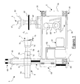
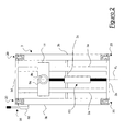
- the tyre-removal machine 1 comprises a box-shaped frame 2 (or "casing") which houses an electric motor 4 supported by a bracket 4a, a perpendicular speed reducer 53 and a belt drive system 55.
- a shaft 54 of the perpendicular reducer 53, projecting from the casing 2 is able to cause rotation of a rotatable wheel-locking plate 5 which locks a wheel with tyre to be mounted/removed (not shown in Figures 1 and 2).
- the casing 2 is substantially in the form of a parallelepiped and is preferably formed with two front uprights 2a and two rear uprights 3b.
- the uprights 2a and 3b preferably consist of metal profiled parts with a closed tubular cross-section.
- the casing 2 defines a front side, a rear side and two opposite flanks. The sides and the flanks are closed by panels. Similarly the upper surface 2c is closed by a panel. The bottom is closed by a base 2b.
- the sides, the flanks, the upper surface and the base are fixed to the uprights 2a, 3b by means of threaded members such as screws and bolts 20.
- the upper closing surface 2c has an opening (not shown) which will be described below.
- the rear uprights extend so as to form a guide column 3.
- the guide column 3 projects from the casing 2 with its axis directed in a first direction d 3 .
- said first direction d 3 is substantially vertical, as shown in Figures 1 and 2.
- the column 3 comprises guides 3a with an axis parallel to the direction d 3 .
- the guides 3a are preferably cylindrical and extend between the base 2b and an upper closing cross-piece 3d.
- the uprights are mounted on the base and on the cross-piece by means of threaded members 20 (for example, screws and bolts).
- a tool-carrying slide 11 is slidable along the guides 3a in the direction d 3 .
- the slide 11 supports a pusher arm 9.
- the pusher arm 9 has an axis directed in a second direction d 9 , preferably substantially perpendicular to the first direction d 3 and therefore horizontal (at least in the most common configuration).
- the pusher arm 9 comprises a piston cylinder 9a and a plunger rod 9b which extends so as to project over the casing 2.
- the rod of the plunger has a non-circular cross-section so that it may not rotate about its axis d 9 .
- the pusher arm 9 has an outer piston 64 fixed to a plate 11 a of the slide 11 and to the rod 9b.
- the tyre-removal machine 1 also comprises a pressurised-fluid circuit.
- said circuit is a hydraulic circuit.
- the hydraulic circuit of the tyre-removal machine 1 comprises an oil-dynamic control unit 60, a hydraulic distributor 61, hydraulic cylinders 63, connection pipes 62 and actuating means of the lever type 65 and pedal type (not shown).
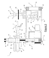
- the end of the plunger rod 9b of the pusher arm 9 also has, fixed thereto, a multifunctional tool 7 comprising a cup-shaped bead-detaching member 7a, a pawl-type bead engaging member 7b, a tyre-mounting finger 7c and a hollow cylinder 7d.
- Said bead-detaching member 7a and said bead engaging member 7b may perform movements which allow them to act on the tyre and performing all the necessary operations for fitting/removal of a wheel tyre. These movements will be described in detail below.
- the rotatable wheel-locking plate 5 comprises a rotatable support plate 50, a threaded shaft 51 and a wheel-locking wing nut 52 which is also threaded.
- the shaft 51 is connected to the shaft 54 of the vertical reducer 53 and projects from the closing surface 2c of the casing.
- the hollow cylinder 7d of the tool 7 is fitted into the rod 9b of the pusher arm 9 and fixed thereto by means of a pin 12 inserted into a proper fixing hole (not shown) of the hollow cylinder 7d and into corresponding fixing holes (not shown) of the rod 9b.
- the pin 12 is preferably spring biased.
- the bead-detaching member 7a is concave.
- it is cup-shaped; more preferably, the bead-detaching member 7a is shaped as a frustoconical cup.
- the cup 7a is engaged on the hollow cylinder 7d by means of bearings 70a.
- the frustoconical cup 7a is made of a material which produces a limited amount of friction when in contact with the rubber of the tyre. More preferably, the frustoconical cup 7a is made of graphite-injected nylon.
- the engaging member 7b comprises a pawl 70b which is shaped as a finger with a curved end.
- a pawl 70b which is shaped as a finger with a curved end.
- two rectangular plates 71 engage the end of the hollow cylinder 7d.
- the plates are parallel one to the other and they are preferably separated by means of spacers 71'.
- each plate 71 has a first cam 72 and a second cam 73.
- the first cam 72 has a first linear portion 72a forming a first angle with the direction d 9 and a second linear portion 72b forming a second angle with the direction d 9 , wherein the second angle is preferably higher than the first angle.
- the second cam 73 is preferably substantially linear, except a "V"-shaped kink 73a.
- the pawl 70b is profitably arranged between the two plates 71. Further, the pawl 70b is provided, at each sides, with two pins 720 and 730, which are engaged with the first and the second cam, respectively of the plates. Thus, the pawl 70b is movable parallel to the plates 71, its movement being guided by the first and the second cams 72 and 73.
- the multifunction tool 7 is provided with an hydraulic piston 74.
- the piston 74 is connected to the hydraulic circuit of the tyre-removal machine by means of a connection pipe (not shown).
- the piston 74 is rotatable around a rotation centre 74a.
- the rod of the piston 74 is preferably connected to the pawl 70b at the pin 730 (or at the pin 720) through a connection element (not shown), so that the piston 74 and the pawl 70b are mutually rotatable in a plane parallel to the plates 71.
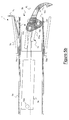
- Figure 5b shows an intermediate stage wherein the pin 730 is engaging the kink 73a of the second cam 73, and the pawl 70b is partially projecting out of the hollow cylinder 7d.
- Figure 5c show the situation wherein the pawl 70b is completely out of the hollow cylinder 7d, so that the engaging member 70b is in its projecting position.
- the tool 7 further comprises a tyre-mounting finger 7c.
- a tyre-mounting finger is fixed to the external surface of the hollow cylinder 7d.
- the tyre-mounting finger 7c may project out of the bead-detaching member 7a in an opposite direction relative to the direction of the pawl 70b when it is in its projecting position, as shown in Figure 6.
- the tyre-mounting finger 7c may projects out of the bead-detaching member 7a in a direction which forms an angle of 120° with respect to the direction of the pawl 70b when it is in its projecting position, as shown in Figure 7.
- the portion of the bead-detaching member 7a which can be freely used for bead-detaching is wider (240° instead of 180°).
- the translational movement of the tool-carrying slide 11 along the guides 3a is operated by at least one piston 63 ( Figures 1-4).
- a pair of pistons 63 is provided. More preferably, said two pistons are fixed integrally opposite each other, namely they are fixed to each other so that their axes are mutually parallel and so that the plunger rods of the two pistons 63 emerge in opposite directions.
- the axis of the two pistons 63 is substantially parallel to the direction d 3 .
- the plunger rod of the cylinder directed downwards is fixed to the base 2b and the plunger rod of the other cylinder is substantially fixed to the arm-carrying slide 11. Owing to this configuration with the pistons arranged opposite each other, a double stroke is obtained compared to the single-piston configuration, while maintaining small dimensions.
- the slide 11 may slide downwards as far as a position where the tool 7 is below the upper surface of the casing.
- the closing surface 2c of the casing 2 has a special opening, as mentioned above.
- the engaging member 7b is in its retracted position and the pusher arm 9 with the tool 7 is displaced into the position where it is situated above the top side of the wheel.
- the tool 7 is rotated around the direction d 9 until either point S1 or point S2 faces the top side of the wheel (embodiment shown in Figure 6).
- the tool 7 is rotated around the direction d 9 until point S3 faces the top side of the wheel.
- the wheel-locking plate is then made to rotate (preferably by means of operation of a pedal, not shown), so that the multifunctional tool 7 acts on the whole top side of the tyre.
- the pusher arm 9 is then moved in the direction of the arrow T1.
- the bead-detaching member 7a rotates when it comes into contact with the top side of the tyre 82, as shown in Figure 8.
- the tool 7 is then moved away from the tyre (not shown) when the upper bead has been detached.
- the lower bead-detaching step is shown in Figure 9.
- the tool 7 is rotated through 180° around the direction d 9 and the engaging member 7b is kept in its retracted position.
- the tool is displaced until it is positioned underneath the bottom side of the wheel 8.
- the pusher arm 9 is then raised in the direction of the arrow T2.
- the cup-shaped member 7a presses against the side of the (rotating) tyre and separates the bead at the bottom.
- the arm 9 is then moved away from the tyre (not shown).
- FIGS. 10a, 10b and 10c The step of engagement with the upper edge of the tyre is shown in Figures 10a, 10b and 10c.
- the pusher arm 9 is displaced vertically until it is situated above the wheel.
- the tool 7 is rotated around the direction d 9 until the projecting direction of the engaging member is parallel to d 3 and directed towards the top side of the wheel.
- the engaging member 7b is initially kept in its retracted position ( Figure 10a). Then, the engaging member 7b is actuated; in its intermediate position, the pawl 70b comes into contact with the upper side of the tyre ( Figure 10b).
- the engaging member 7b is preferably retracted.
- the tool 7 is preferably rotated through 180° around the direction d 9 .
- the arm 9 is then positioned underneath the wheel with the member 7a opposite to the tyre ( Figure 11 a).
- the arm 9 is raised (arrow T2, Figure 11 a), the member 7a presses against the bottom side of the tyre 82 and raises it, thus extracting it from the rim 81.
- the tyre-removal machine according to the present invention has a particularly simple structure owing to the fact that the bead-detaching, engaging and tyre-removing functions are all performed by a single multifunctional tool.
- the structural simplicity results in easy assembly and reduced costs.
- the two members of the multi-functional tool are arranged so that they do not interfere with each other.
- the bead-detaching member can be designed to be large enough to handle tyres of different size and having strong shoulders.
- the arrangement according to the invention is more robust than the known devices, in particular than the device according to EP 1.314.584 A1.
- the bead engaging member 7b, in its retracted state, is protected by the member 7a and possibly also by hollow cylinder 7d. This arrangement also protect the bead engaging member 7b from dust or the like.
- a further advantage of the present invention consists in an increase in the ease of manufacture of the casing.
- the casing is formed by assembling, using threaded members, a set of uprights and panels, an operation which is more versatile than the traditional manufacturing method using folded and shaped metal sheets.
- this casing structure allows a reduction in the storage and transportation costs, since the casing may be stored and transported in unassembled form, with a considerable reduction in the occupied space.
Landscapes
- Engineering & Computer Science (AREA)
- Mechanical Engineering (AREA)
- Automatic Assembly (AREA)
- Mechanical Pencils And Projecting And Retracting Systems Therefor, And Multi-System Writing Instruments (AREA)
Applications Claiming Priority (1)
| Application Number | Priority Date | Filing Date | Title |
|---|---|---|---|
| IT001570A ITMI20041570A1 (it) | 2004-07-30 | 2004-07-30 | "macchina smontagomme a singolo utensile plurifunzione" |
Publications (3)
| Publication Number | Publication Date |
|---|---|
| EP1625954A2 true EP1625954A2 (de) | 2006-02-15 |
| EP1625954A3 EP1625954A3 (de) | 2006-03-01 |
| EP1625954B1 EP1625954B1 (de) | 2011-12-28 |
Family
ID=34956294
Family Applications (1)
| Application Number | Title | Priority Date | Filing Date |
|---|---|---|---|
| EP05076693A Expired - Lifetime EP1625954B1 (de) | 2004-07-30 | 2005-07-22 | Reifendemontiervorrichtung mit einem einzigen Multifunktionswerkzeug |
Country Status (3)
| Country | Link |
|---|---|
| EP (1) | EP1625954B1 (de) |
| AT (1) | ATE538953T1 (de) |
| IT (1) | ITMI20041570A1 (de) |
Cited By (11)
| Publication number | Priority date | Publication date | Assignee | Title |
|---|---|---|---|---|
| EP1897708A1 (de) * | 2006-09-08 | 2008-03-12 | Giuliano S.P.A. | Maschine zum Anbringen und Abnehmen von Reifen und Felgen für Fahrzeuge |
| EP1916125A1 (de) * | 2006-10-27 | 2008-04-30 | C.M.L. s.n.c. di Marco Galbiati & C. | Betriebskopf für eine Reifenentfernungsmaschine und entsprechende Reifenentfernungsmaschine |
| WO2008080584A3 (de) * | 2007-01-04 | 2008-09-25 | Michael Immler | Montagevorrichtung und verfahren zur montage und demontage eines fahrzeugreifens auf einer felge |
| CN101439650A (zh) * | 2007-11-21 | 2009-05-27 | 古丽亚诺股份公司 | 用于安装和拆卸车辆用车轮轮胎的机械 |
| WO2009138322A1 (en) * | 2008-05-15 | 2009-11-19 | Corghi S.P.A. | A tyre-removing method and a tyre-changing machine |
| JP2014162325A (ja) * | 2013-02-25 | 2014-09-08 | Onodani Kiko Kk | タイヤの着脱方法 |
| JP2014162326A (ja) * | 2013-02-25 | 2014-09-08 | Onodani Kiko Kk | タイヤ着脱装置及びツール |
| CN104890458A (zh) * | 2015-06-16 | 2015-09-09 | 毕作亮 | 轮胎校正机 |
| EP2949486B1 (de) | 2014-05-30 | 2019-01-09 | Snap-on Equipment Srl a unico socio | Verfahren zur Montage und Demontage eines Reifens auf und von einer Radfelge |
| WO2022222669A1 (zh) * | 2021-04-22 | 2022-10-27 | 南京沃宇机电有限公司 | 一种立式轮胎拆装机器人 |
| IT202200010763A1 (it) * | 2022-05-24 | 2023-11-24 | M & B Eng S R L | Dispositivo per il montaggio/smontaggio di pneumatici |
Families Citing this family (1)
| Publication number | Priority date | Publication date | Assignee | Title |
|---|---|---|---|---|
| US12054016B2 (en) | 2020-12-10 | 2024-08-06 | Nexion S.P.A. | Working head for a tyre changing apparatus |
Citations (3)
| Publication number | Priority date | Publication date | Assignee | Title |
|---|---|---|---|---|
| EP1177920A2 (de) | 2000-08-03 | 2002-02-06 | CORGHI S.p.A. | Automatische Radmontier- und Demontiervorrichtung und damit ausgestattetes Radmontagegerät |
| EP1314584A1 (de) | 2001-11-22 | 2003-05-28 | BUTLER ENGINEERING & MARKETING S.r.l. | Wulstabdrückeinheit für eine Reifenmontiermaschine |
| EP1475252A1 (de) | 2003-05-09 | 2004-11-10 | Giuliano S.r.l. | Montage- und Demontagemaschine für Reifen auf Fahrzeugfelgen |
Family Cites Families (1)
| Publication number | Priority date | Publication date | Assignee | Title |
|---|---|---|---|---|
| JPS57158109A (en) * | 1981-03-26 | 1982-09-29 | Maruyama Seiki Kk | Equipment for mounting/demounting tire |
-
2004
- 2004-07-30 IT IT001570A patent/ITMI20041570A1/it unknown
-
2005
- 2005-07-22 EP EP05076693A patent/EP1625954B1/de not_active Expired - Lifetime
- 2005-07-22 AT AT05076693T patent/ATE538953T1/de active
Patent Citations (3)
| Publication number | Priority date | Publication date | Assignee | Title |
|---|---|---|---|---|
| EP1177920A2 (de) | 2000-08-03 | 2002-02-06 | CORGHI S.p.A. | Automatische Radmontier- und Demontiervorrichtung und damit ausgestattetes Radmontagegerät |
| EP1314584A1 (de) | 2001-11-22 | 2003-05-28 | BUTLER ENGINEERING & MARKETING S.r.l. | Wulstabdrückeinheit für eine Reifenmontiermaschine |
| EP1475252A1 (de) | 2003-05-09 | 2004-11-10 | Giuliano S.r.l. | Montage- und Demontagemaschine für Reifen auf Fahrzeugfelgen |
Cited By (18)
| Publication number | Priority date | Publication date | Assignee | Title |
|---|---|---|---|---|
| CN101138942B (zh) * | 2006-09-08 | 2012-07-04 | 古丽亚诺集团股份公司 | 用于安装和拆卸车辆的轮胎和轮圈的机器 |
| JP2008062923A (ja) * | 2006-09-08 | 2008-03-21 | Giuliano Spa | 乗物用タイヤおよびホイールリムの取り付けおよび取り外し機械 |
| EP1897708A1 (de) * | 2006-09-08 | 2008-03-12 | Giuliano S.P.A. | Maschine zum Anbringen und Abnehmen von Reifen und Felgen für Fahrzeuge |
| US7455096B2 (en) | 2006-09-08 | 2008-11-25 | Giuliano S.P.A. | Machine for fitting and removing tires and wheel rims for vehicles |
| EP1916125A1 (de) * | 2006-10-27 | 2008-04-30 | C.M.L. s.n.c. di Marco Galbiati & C. | Betriebskopf für eine Reifenentfernungsmaschine und entsprechende Reifenentfernungsmaschine |
| US8215366B2 (en) | 2007-01-04 | 2012-07-10 | Immler Michael | Mounting device, and method for mounting and dismounting a vehicle tire on and from a rim |
| WO2008080584A3 (de) * | 2007-01-04 | 2008-09-25 | Michael Immler | Montagevorrichtung und verfahren zur montage und demontage eines fahrzeugreifens auf einer felge |
| US8714228B2 (en) | 2007-01-04 | 2014-05-06 | Robert Bosch Gmbh | Mounting device, and method for mounting and dismounting a vehicle tire on a wheel rim |
| CN101439650A (zh) * | 2007-11-21 | 2009-05-27 | 古丽亚诺股份公司 | 用于安装和拆卸车辆用车轮轮胎的机械 |
| WO2009138322A1 (en) * | 2008-05-15 | 2009-11-19 | Corghi S.P.A. | A tyre-removing method and a tyre-changing machine |
| JP2014162325A (ja) * | 2013-02-25 | 2014-09-08 | Onodani Kiko Kk | タイヤの着脱方法 |
| JP2014162326A (ja) * | 2013-02-25 | 2014-09-08 | Onodani Kiko Kk | タイヤ着脱装置及びツール |
| EP2949486B1 (de) | 2014-05-30 | 2019-01-09 | Snap-on Equipment Srl a unico socio | Verfahren zur Montage und Demontage eines Reifens auf und von einer Radfelge |
| EP2949486B2 (de) † | 2014-05-30 | 2022-04-13 | Snap-on Equipment Srl a unico socio | Verfahren zur Montage und Demontage eines Reifens auf und von einer Radfelge |
| CN104890458A (zh) * | 2015-06-16 | 2015-09-09 | 毕作亮 | 轮胎校正机 |
| WO2022222669A1 (zh) * | 2021-04-22 | 2022-10-27 | 南京沃宇机电有限公司 | 一种立式轮胎拆装机器人 |
| IT202200010763A1 (it) * | 2022-05-24 | 2023-11-24 | M & B Eng S R L | Dispositivo per il montaggio/smontaggio di pneumatici |
| WO2023228009A1 (en) * | 2022-05-24 | 2023-11-30 | M & B Engineering S.R.L. | Device for fitting/removing tires |
Also Published As
| Publication number | Publication date |
|---|---|
| ATE538953T1 (de) | 2012-01-15 |
| EP1625954B1 (de) | 2011-12-28 |
| ITMI20041570A1 (it) | 2004-10-30 |
| EP1625954A3 (de) | 2006-03-01 |
Similar Documents
| Publication | Publication Date | Title |
|---|---|---|
| EP1625954B1 (de) | Reifendemontiervorrichtung mit einem einzigen Multifunktionswerkzeug | |
| JP4073299B2 (ja) | タイヤ着脱装置のビード取りはずし用ヘッド | |
| EP1897708B1 (de) | Maschine zum Anbringen und Abnehmen von Reifen und Felgen für Fahrzeuge | |
| CN1680124A (zh) | 轮胎组装-拆卸机的自动检测装置 | |
| JP2002029231A (ja) | タイヤ取り外し機用の自動ビード解放装置及びそれを具備したタイヤ取り外し機 | |
| JP6632241B2 (ja) | タイヤ付ホイールを取り付けおよび/または取り外しするための装置、タイヤ取り付け・取り外しマシン、およびタイヤ付ホイールのリムからタイヤを取り外しするための方法 | |
| EP1916125B1 (de) | Betriebskopf für eine Reifenentfernungsmaschine und entsprechende Reifenentfernungsmaschine | |
| JP2006290340A (ja) | 横転可能な取付け・取外し工具を備える着脱装置 | |
| US8770566B2 (en) | Removably supporting mechanism for workpiece holding device and workpiece holding device replacement and support apparatus | |
| US3847198A (en) | Centerpost drive mechanism | |
| JP3338347B2 (ja) | 車両用タイヤインフレータ | |
| CN117706331A (zh) | 一种主板测试冶具及主板测试装置 | |
| GB1590089A (en) | Workpiece feed mechanism | |
| CN111043086B (zh) | 一种自动蓄能装置、及应用其的货物升降装置 | |
| JP5283657B2 (ja) | ホイール抜出装置 | |
| CN111043918B (zh) | 一种弹头自动刮药设备 | |
| CA2655102C (en) | Elevating mechanism for jaws for clamping mouldings | |
| JP2003341322A (ja) | 産業車両用タイヤ取付け、取外し装置 | |
| CN113103832B (zh) | 一种立式轮胎拆装机器人 | |
| HK1088287A (en) | Tyre-removal machine with single multifunctional tool | |
| CN108273906B (zh) | 一种风机筒体自动翻边打孔机 | |
| CN118219022B (zh) | 一种齿轮中心打孔定位具 | |
| CN220461955U (zh) | 一种空调吸气管冲压加工模具 | |
| CN108817916B (zh) | 新能源汽车转轴制造机器人 | |
| CN109650022A (zh) | Xy轴移载机 |
Legal Events
| Date | Code | Title | Description |
|---|---|---|---|
| PUAI | Public reference made under article 153(3) epc to a published international application that has entered the european phase |
Free format text: ORIGINAL CODE: 0009012 |
|
| PUAL | Search report despatched |
Free format text: ORIGINAL CODE: 0009013 |
|
| AK | Designated contracting states |
Kind code of ref document: A2 Designated state(s): AT BE BG CH CY CZ DE DK EE ES FI FR GB GR HU IE IS IT LI LT LU LV MC NL PL PT RO SE SI SK TR |
|
| AX | Request for extension of the european patent |
Extension state: AL BA HR MK YU |
|
| AK | Designated contracting states |
Kind code of ref document: A3 Designated state(s): AT BE BG CH CY CZ DE DK EE ES FI FR GB GR HU IE IS IT LI LT LU LV MC NL PL PT RO SE SI SK TR |
|
| AX | Request for extension of the european patent |
Extension state: AL BA HR MK YU |
|
| 17P | Request for examination filed |
Effective date: 20060803 |
|
| REG | Reference to a national code |
Ref country code: HK Ref legal event code: DE Ref document number: 1088287 Country of ref document: HK |
|
| AKX | Designation fees paid |
Designated state(s): AT BE BG CH CY CZ DE DK EE ES FI FR GB GR HU IE IS IT LI LT LU LV MC NL PL PT RO SE SI SK TR |
|
| 17Q | First examination report despatched |
Effective date: 20090202 |
|
| GRAP | Despatch of communication of intention to grant a patent |
Free format text: ORIGINAL CODE: EPIDOSNIGR1 |
|
| GRAS | Grant fee paid |
Free format text: ORIGINAL CODE: EPIDOSNIGR3 |
|
| GRAA | (expected) grant |
Free format text: ORIGINAL CODE: 0009210 |
|
| AK | Designated contracting states |
Kind code of ref document: B1 Designated state(s): AT BE BG CH CY CZ DE DK EE ES FI FR GB GR HU IE IS IT LI LT LU LV MC NL PL PT RO SE SI SK TR |
|
| REG | Reference to a national code |
Ref country code: GB Ref legal event code: FG4D |
|
| REG | Reference to a national code |
Ref country code: CH Ref legal event code: EP |
|
| REG | Reference to a national code |
Ref country code: AT Ref legal event code: REF Ref document number: 538953 Country of ref document: AT Kind code of ref document: T Effective date: 20120115 |
|
| REG | Reference to a national code |
Ref country code: IE Ref legal event code: FG4D |
|
| REG | Reference to a national code |
Ref country code: DE Ref legal event code: R096 Ref document number: 602005031842 Country of ref document: DE Effective date: 20120308 |
|
| REG | Reference to a national code |
Ref country code: NL Ref legal event code: VDEP Effective date: 20111228 |
|
| PG25 | Lapsed in a contracting state [announced via postgrant information from national office to epo] |
Ref country code: LT Free format text: LAPSE BECAUSE OF FAILURE TO SUBMIT A TRANSLATION OF THE DESCRIPTION OR TO PAY THE FEE WITHIN THE PRESCRIBED TIME-LIMIT Effective date: 20111228 |
|
| LTIE | Lt: invalidation of european patent or patent extension |
Effective date: 20111228 |
|
| PG25 | Lapsed in a contracting state [announced via postgrant information from national office to epo] |
Ref country code: GR Free format text: LAPSE BECAUSE OF FAILURE TO SUBMIT A TRANSLATION OF THE DESCRIPTION OR TO PAY THE FEE WITHIN THE PRESCRIBED TIME-LIMIT Effective date: 20120329 Ref country code: SI Free format text: LAPSE BECAUSE OF FAILURE TO SUBMIT A TRANSLATION OF THE DESCRIPTION OR TO PAY THE FEE WITHIN THE PRESCRIBED TIME-LIMIT Effective date: 20111228 Ref country code: SE Free format text: LAPSE BECAUSE OF FAILURE TO SUBMIT A TRANSLATION OF THE DESCRIPTION OR TO PAY THE FEE WITHIN THE PRESCRIBED TIME-LIMIT Effective date: 20111228 Ref country code: LV Free format text: LAPSE BECAUSE OF FAILURE TO SUBMIT A TRANSLATION OF THE DESCRIPTION OR TO PAY THE FEE WITHIN THE PRESCRIBED TIME-LIMIT Effective date: 20111228 |
|
| PG25 | Lapsed in a contracting state [announced via postgrant information from national office to epo] |
Ref country code: CY Free format text: LAPSE BECAUSE OF FAILURE TO SUBMIT A TRANSLATION OF THE DESCRIPTION OR TO PAY THE FEE WITHIN THE PRESCRIBED TIME-LIMIT Effective date: 20111228 Ref country code: BE Free format text: LAPSE BECAUSE OF FAILURE TO SUBMIT A TRANSLATION OF THE DESCRIPTION OR TO PAY THE FEE WITHIN THE PRESCRIBED TIME-LIMIT Effective date: 20111228 |
|
| PG25 | Lapsed in a contracting state [announced via postgrant information from national office to epo] |
Ref country code: BG Free format text: LAPSE BECAUSE OF FAILURE TO SUBMIT A TRANSLATION OF THE DESCRIPTION OR TO PAY THE FEE WITHIN THE PRESCRIBED TIME-LIMIT Effective date: 20120328 Ref country code: EE Free format text: LAPSE BECAUSE OF FAILURE TO SUBMIT A TRANSLATION OF THE DESCRIPTION OR TO PAY THE FEE WITHIN THE PRESCRIBED TIME-LIMIT Effective date: 20111228 Ref country code: SK Free format text: LAPSE BECAUSE OF FAILURE TO SUBMIT A TRANSLATION OF THE DESCRIPTION OR TO PAY THE FEE WITHIN THE PRESCRIBED TIME-LIMIT Effective date: 20111228 Ref country code: NL Free format text: LAPSE BECAUSE OF FAILURE TO SUBMIT A TRANSLATION OF THE DESCRIPTION OR TO PAY THE FEE WITHIN THE PRESCRIBED TIME-LIMIT Effective date: 20111228 Ref country code: CZ Free format text: LAPSE BECAUSE OF FAILURE TO SUBMIT A TRANSLATION OF THE DESCRIPTION OR TO PAY THE FEE WITHIN THE PRESCRIBED TIME-LIMIT Effective date: 20111228 Ref country code: IS Free format text: LAPSE BECAUSE OF FAILURE TO SUBMIT A TRANSLATION OF THE DESCRIPTION OR TO PAY THE FEE WITHIN THE PRESCRIBED TIME-LIMIT Effective date: 20120428 |
|
| PG25 | Lapsed in a contracting state [announced via postgrant information from national office to epo] |
Ref country code: RO Free format text: LAPSE BECAUSE OF FAILURE TO SUBMIT A TRANSLATION OF THE DESCRIPTION OR TO PAY THE FEE WITHIN THE PRESCRIBED TIME-LIMIT Effective date: 20111228 Ref country code: PT Free format text: LAPSE BECAUSE OF FAILURE TO SUBMIT A TRANSLATION OF THE DESCRIPTION OR TO PAY THE FEE WITHIN THE PRESCRIBED TIME-LIMIT Effective date: 20120430 Ref country code: PL Free format text: LAPSE BECAUSE OF FAILURE TO SUBMIT A TRANSLATION OF THE DESCRIPTION OR TO PAY THE FEE WITHIN THE PRESCRIBED TIME-LIMIT Effective date: 20111228 |
|
| REG | Reference to a national code |
Ref country code: AT Ref legal event code: MK05 Ref document number: 538953 Country of ref document: AT Kind code of ref document: T Effective date: 20111228 |
|
| PG25 | Lapsed in a contracting state [announced via postgrant information from national office to epo] |
Ref country code: DK Free format text: LAPSE BECAUSE OF FAILURE TO SUBMIT A TRANSLATION OF THE DESCRIPTION OR TO PAY THE FEE WITHIN THE PRESCRIBED TIME-LIMIT Effective date: 20111228 |
|
| PGFP | Annual fee paid to national office [announced via postgrant information from national office to epo] |
Ref country code: GB Payment date: 20120723 Year of fee payment: 8 |
|
| PLBE | No opposition filed within time limit |
Free format text: ORIGINAL CODE: 0009261 |
|
| STAA | Information on the status of an ep patent application or granted ep patent |
Free format text: STATUS: NO OPPOSITION FILED WITHIN TIME LIMIT |
|
| 26N | No opposition filed |
Effective date: 20121001 |
|
| PGFP | Annual fee paid to national office [announced via postgrant information from national office to epo] |
Ref country code: DE Payment date: 20120726 Year of fee payment: 8 Ref country code: IT Payment date: 20120720 Year of fee payment: 8 Ref country code: FR Payment date: 20120806 Year of fee payment: 8 |
|
| REG | Reference to a national code |
Ref country code: DE Ref legal event code: R097 Ref document number: 602005031842 Country of ref document: DE Effective date: 20121001 |
|
| PG25 | Lapsed in a contracting state [announced via postgrant information from national office to epo] |
Ref country code: AT Free format text: LAPSE BECAUSE OF FAILURE TO SUBMIT A TRANSLATION OF THE DESCRIPTION OR TO PAY THE FEE WITHIN THE PRESCRIBED TIME-LIMIT Effective date: 20111228 |
|
| REG | Reference to a national code |
Ref country code: HK Ref legal event code: WD Ref document number: 1088287 Country of ref document: HK |
|
| PG25 | Lapsed in a contracting state [announced via postgrant information from national office to epo] |
Ref country code: MC Free format text: LAPSE BECAUSE OF NON-PAYMENT OF DUE FEES Effective date: 20120731 |
|
| REG | Reference to a national code |
Ref country code: CH Ref legal event code: PL |
|
| PG25 | Lapsed in a contracting state [announced via postgrant information from national office to epo] |
Ref country code: LI Free format text: LAPSE BECAUSE OF NON-PAYMENT OF DUE FEES Effective date: 20120731 Ref country code: ES Free format text: LAPSE BECAUSE OF FAILURE TO SUBMIT A TRANSLATION OF THE DESCRIPTION OR TO PAY THE FEE WITHIN THE PRESCRIBED TIME-LIMIT Effective date: 20120408 Ref country code: CH Free format text: LAPSE BECAUSE OF NON-PAYMENT OF DUE FEES Effective date: 20120731 |
|
| REG | Reference to a national code |
Ref country code: IE Ref legal event code: MM4A |
|
| PG25 | Lapsed in a contracting state [announced via postgrant information from national office to epo] |
Ref country code: FI Free format text: LAPSE BECAUSE OF FAILURE TO SUBMIT A TRANSLATION OF THE DESCRIPTION OR TO PAY THE FEE WITHIN THE PRESCRIBED TIME-LIMIT Effective date: 20111228 |
|
| PG25 | Lapsed in a contracting state [announced via postgrant information from national office to epo] |
Ref country code: IE Free format text: LAPSE BECAUSE OF NON-PAYMENT OF DUE FEES Effective date: 20120722 |
|
| GBPC | Gb: european patent ceased through non-payment of renewal fee |
Effective date: 20130722 |
|
| REG | Reference to a national code |
Ref country code: DE Ref legal event code: R119 Ref document number: 602005031842 Country of ref document: DE Effective date: 20140201 |
|
| REG | Reference to a national code |
Ref country code: FR Ref legal event code: ST Effective date: 20140331 |
|
| PG25 | Lapsed in a contracting state [announced via postgrant information from national office to epo] |
Ref country code: DE Free format text: LAPSE BECAUSE OF NON-PAYMENT OF DUE FEES Effective date: 20140201 Ref country code: GB Free format text: LAPSE BECAUSE OF NON-PAYMENT OF DUE FEES Effective date: 20130722 Ref country code: TR Free format text: LAPSE BECAUSE OF FAILURE TO SUBMIT A TRANSLATION OF THE DESCRIPTION OR TO PAY THE FEE WITHIN THE PRESCRIBED TIME-LIMIT Effective date: 20111228 |
|
| PG25 | Lapsed in a contracting state [announced via postgrant information from national office to epo] |
Ref country code: IT Free format text: LAPSE BECAUSE OF NON-PAYMENT OF DUE FEES Effective date: 20130722 Ref country code: FR Free format text: LAPSE BECAUSE OF NON-PAYMENT OF DUE FEES Effective date: 20130731 Ref country code: LU Free format text: LAPSE BECAUSE OF NON-PAYMENT OF DUE FEES Effective date: 20120722 |
|
| PG25 | Lapsed in a contracting state [announced via postgrant information from national office to epo] |
Ref country code: HU Free format text: LAPSE BECAUSE OF FAILURE TO SUBMIT A TRANSLATION OF THE DESCRIPTION OR TO PAY THE FEE WITHIN THE PRESCRIBED TIME-LIMIT Effective date: 20050722 |