EP1626103A2 - Lochmasken-Rahmenanordnung für die Abscheidung von dünnen Schichten und mittels dieser Anordnung hergestellte organische lichtemittierende Anzeigevorrichtung - Google Patents
Lochmasken-Rahmenanordnung für die Abscheidung von dünnen Schichten und mittels dieser Anordnung hergestellte organische lichtemittierende Anzeigevorrichtung Download PDFInfo
- Publication number
- EP1626103A2 EP1626103A2 EP05106299A EP05106299A EP1626103A2 EP 1626103 A2 EP1626103 A2 EP 1626103A2 EP 05106299 A EP05106299 A EP 05106299A EP 05106299 A EP05106299 A EP 05106299A EP 1626103 A2 EP1626103 A2 EP 1626103A2
- Authority
- EP
- European Patent Office
- Prior art keywords
- mask
- frame assembly
- mask frame
- gap
- unit
- Prior art date
- Legal status (The legal status is an assumption and is not a legal conclusion. Google has not performed a legal analysis and makes no representation as to the accuracy of the status listed.)
- Granted
Links
Images


Classifications
-
- C—CHEMISTRY; METALLURGY
- C23—COATING METALLIC MATERIAL; COATING MATERIAL WITH METALLIC MATERIAL; CHEMICAL SURFACE TREATMENT; DIFFUSION TREATMENT OF METALLIC MATERIAL; COATING BY VACUUM EVAPORATION, BY SPUTTERING, BY ION IMPLANTATION OR BY CHEMICAL VAPOUR DEPOSITION, IN GENERAL; INHIBITING CORROSION OF METALLIC MATERIAL OR INCRUSTATION IN GENERAL
- C23C—COATING METALLIC MATERIAL; COATING MATERIAL WITH METALLIC MATERIAL; SURFACE TREATMENT OF METALLIC MATERIAL BY DIFFUSION INTO THE SURFACE, BY CHEMICAL CONVERSION OR SUBSTITUTION; COATING BY VACUUM EVAPORATION, BY SPUTTERING, BY ION IMPLANTATION OR BY CHEMICAL VAPOUR DEPOSITION, IN GENERAL
- C23C14/00—Coating by vacuum evaporation, by sputtering or by ion implantation of the coating forming material
- C23C14/06—Coating by vacuum evaporation, by sputtering or by ion implantation of the coating forming material characterised by the coating material
- C23C14/12—Organic material
-
- H—ELECTRICITY
- H05—ELECTRIC TECHNIQUES NOT OTHERWISE PROVIDED FOR
- H05B—ELECTRIC HEATING; ELECTRIC LIGHT SOURCES NOT OTHERWISE PROVIDED FOR; CIRCUIT ARRANGEMENTS FOR ELECTRIC LIGHT SOURCES, IN GENERAL
- H05B33/00—Electroluminescent light sources
- H05B33/10—Apparatus or processes specially adapted to the manufacture of electroluminescent light sources
-
- C—CHEMISTRY; METALLURGY
- C23—COATING METALLIC MATERIAL; COATING MATERIAL WITH METALLIC MATERIAL; CHEMICAL SURFACE TREATMENT; DIFFUSION TREATMENT OF METALLIC MATERIAL; COATING BY VACUUM EVAPORATION, BY SPUTTERING, BY ION IMPLANTATION OR BY CHEMICAL VAPOUR DEPOSITION, IN GENERAL; INHIBITING CORROSION OF METALLIC MATERIAL OR INCRUSTATION IN GENERAL
- C23C—COATING METALLIC MATERIAL; COATING MATERIAL WITH METALLIC MATERIAL; SURFACE TREATMENT OF METALLIC MATERIAL BY DIFFUSION INTO THE SURFACE, BY CHEMICAL CONVERSION OR SUBSTITUTION; COATING BY VACUUM EVAPORATION, BY SPUTTERING, BY ION IMPLANTATION OR BY CHEMICAL VAPOUR DEPOSITION, IN GENERAL
- C23C14/00—Coating by vacuum evaporation, by sputtering or by ion implantation of the coating forming material
- C23C14/04—Coating on selected surface areas, e.g. using masks
- C23C14/042—Coating on selected surface areas, e.g. using masks using masks
-
- H—ELECTRICITY
- H10—SEMICONDUCTOR DEVICES; ELECTRIC SOLID-STATE DEVICES NOT OTHERWISE PROVIDED FOR
- H10K—ORGANIC ELECTRIC SOLID-STATE DEVICES
- H10K59/00—Integrated devices, or assemblies of multiple devices, comprising at least one organic light-emitting element covered by group H10K50/00
- H10K59/30—Devices specially adapted for multicolour light emission
- H10K59/35—Devices specially adapted for multicolour light emission comprising red-green-blue [RGB] subpixels
-
- H—ELECTRICITY
- H10—SEMICONDUCTOR DEVICES; ELECTRIC SOLID-STATE DEVICES NOT OTHERWISE PROVIDED FOR
- H10K—ORGANIC ELECTRIC SOLID-STATE DEVICES
- H10K71/00—Manufacture or treatment specially adapted for the organic devices covered by this subclass
- H10K71/10—Deposition of organic active material
- H10K71/16—Deposition of organic active material using physical vapour deposition [PVD], e.g. vacuum deposition or sputtering
- H10K71/164—Deposition of organic active material using physical vapour deposition [PVD], e.g. vacuum deposition or sputtering using vacuum deposition
-
- H—ELECTRICITY
- H10—SEMICONDUCTOR DEVICES; ELECTRIC SOLID-STATE DEVICES NOT OTHERWISE PROVIDED FOR
- H10K—ORGANIC ELECTRIC SOLID-STATE DEVICES
- H10K71/00—Manufacture or treatment specially adapted for the organic devices covered by this subclass
- H10K71/10—Deposition of organic active material
- H10K71/16—Deposition of organic active material using physical vapour deposition [PVD], e.g. vacuum deposition or sputtering
- H10K71/166—Deposition of organic active material using physical vapour deposition [PVD], e.g. vacuum deposition or sputtering using selective deposition, e.g. using a mask
-
- H—ELECTRICITY
- H10—SEMICONDUCTOR DEVICES; ELECTRIC SOLID-STATE DEVICES NOT OTHERWISE PROVIDED FOR
- H10K—ORGANIC ELECTRIC SOLID-STATE DEVICES
- H10K71/00—Manufacture or treatment specially adapted for the organic devices covered by this subclass
Definitions
- the present invention relates to a mask frame assembly and an organic light emitting display (OLED) device manufactured using the mask frame assembly, and more particularly, to a mask frame assembly for depositing a thin layer and an OLED device manufactured using the mask frame assembly.
- OLED organic light emitting display
- self-emissive OLED display devices are expected to be next generation display devices since they may have a wide viewing angle, high contrast, and high response speed.
- Display devices may be inorganic light emitting display devices and OLED devices according to the material that forms the light emitting layer.
- the OLED devices are typically brighter than inorganic devices, and they have a higher response speed. Additionally, they can display color images.
- the OLED device comprises a first electrode formed in a predetermined pattern on a substrate, an organic light emitting layer, which may be formed by vacuum evaporation, on the substrate having the first electrode, and a second electrode (cathode) formed in a direction crossing the first electrode on the organic light emitting layer.
- the first electrode may be formed of indium tin oxide (ITO), and the ITO may be patterned using a photolithography method.
- the ITO may be patterned by wet etching with an etching solution including ferric chloride FeCl 3 .
- the second electrode is also etched using photolithography, moisture may penetrate a surface between the organic light emitting layer and the second electrode when exfoliating a resist and etching the second electrode, which reduces the OLED's performance and lifetime.
- a method of depositing materials for forming an organic light emitting layer and a second electrode has been suggested to solve this problem.
- a stripe-shape first electrode formed of ITO is formed on a transparent insulating substrate using a photolithography method. After stacking an organic light emitting layer on the substrate having the first electrode, a mask having the same pattern as the second electrode is arranged contacting the organic light emitting layer, and a second electrode is formed by depositing a material for forming the second electrode.
- Korea Laid-Open Patent Publication 2000-060589 discloses a mask for depositing the organic light emitting layer or the second electrode, an OLED device that uses the mask, and a method of manufacturing the OLED device.
- the mask disclosed in Korea Laid-Open Patent Publication 2000-060589 has slots in a stripe shape spaced a predetermined distance from each other on a main body of a thin film.
- a mask disclosed in Korea Laid-Open Patent Publication 1998-0071583 has a mesh shaped slit part and a bridge part on a metal thin film.
- a mask disclosed in Japanese Patent laid-open Publication No 2000-12238 includes an electrode mask part and a pair of terminal mask units.
- the electrode mask part has a width corresponding to a gap between second electrode (i.e. cathodes), a plurality of marking parts in a stripe shape disposed parallel to each other, and a connection part that connects both ends of each marking part.
- the conventional masks described above may not closely adhere to the substrate due to their weight even though a frame of the mask is tensioned to support an edge of a metal thin film in which long, stripe-shaped holes are formed. This problem is more severe as substrate size increases. Also, when the cathode is deposited, sagging due to the weight of the slot strips increases since heat applied to the mask causes it to expand.
- FIG. 1 is an exploded perspective view showing a conventional mask used for mass production.
- masking pattern units 12 for depositing a plurality of unit substrates that form an OLED device are included on a metal thin film 11, and the mask is fixed to a frame 20 while applying tension to the mask.
- the sagging problem of the conventional mask 10 may be more severe even though tension is uniformly applied to the frame 20 formed in a lattice shape since the mask 10 is large.
- a large metal thin film mask should be welded to the frame 20 so that a width of slots 12a formed on each of the masking pattern units 12 may be maintained within a tolerance range. If tension is applied to prevent the mask 10 from sagging, the welding within a tolerance range is difficult since a slot 12a pitch of each of the masking pattern units 12 may be deformed. If the slot 12a of the masking pattern units 12 of a particular portion of the mask 10 is deformed, a deformation force is applied to all neighboring slots. Therefore, the designed pattern deviates from a tolerance range since the slots 12a move relative to the substrate to be deposited. This problem arises in a vertical direction to the length direction of the slots 12a formed on the mask.
- the supporting bars 21 of both sides of the frame 20 may curve inward of the mask 10 and the upper and lower supporting bars 22 may bow outward, or, as FIG. 3 shows, both side supporting bars 21 may bow outward and the upper and lower supporting bars 22 may curve inward.
- the deformations make it more difficult to control a total pitch difference between the masking pattern units 12 and the electrode pattern units formed on the substrate even if the mask 10 is welded to the frame 20 by applying uniform tension to the mask 10.
- Japanese Patent Laid-Open publication 2001-247961 discloses a mask for solving a problem of creep deformation of strips that form slots due to thermal expansion of the mask.
- the disclosed mask is a deposition mask used for forming a patterning film by deposition on a substrate and includes a mask part having a plurality ofbarrier ribs that define first openings and a screen part in which a plurality of second openings, which have a smaller opening area than each first opening, include magnetic materials disposed on each of the first openings of the mask unit.
- Japanese Patent Laid-Open publication 2001-273979 discloses a structure of a magnetic mask
- Japanese Patent Laid-Open publication 2001-254169 discloses a structure of a mask frame for masking a deposition region by adhering to a material to be deposited.
- the mask frame, on which a mask pattern corresponding to a deposition region is formed includes a mask pattern having fine patterning units, which are supported by fine ribs.
- Japanese Patent Laid-Open publication 2002-235165 and U.S. Patent No. 3,241,519 disclose masks for preventing thermal deformation of openings and improving precision.
- a mask in which a plurality of unit patterns are formed on a single frame and mask for a large display pattern has been disclosed in European Patent Laid-Open Publication EP 1,209,522 A2, and similar masks have been disclosed in U.S. Published Application No. 2002/0025406 A1.
- EP 1,209,522 A2 European Patent Laid-Open Publication
- Similar masks have been disclosed in U.S. Published Application No. 2002/0025406 A1.
- these masks also have the same problems described above.
- EP 1,229,144 A2 discloses a mask frame assembly in which a plurality of masks are supported by a single frame having openings corresponding to each of the masks.
- this mask may waste substrate to be deposited due to the limitation of reducing gaps between masks, and the fabrication of masks is complicated. Therefore, this mask may not be suitable for forming a large size display pattern.
- Applicant's Korean Patent Publication 2003-0046090 discloses a mask frame assembly to solve the above problems.
- the mask includes at least two unit masks on which at least one masking pattern unit is formed in a length direction of the mask. However, a gap between the unit masks can be hardly reduced.
- the present invention provides a mask frame assembly for depositing a thin film by which a total pitch between deposited patterns may be easily controlled and a deposited pattern deformation due to the increase in a size of masking pattern units may be reduced.
- the present invention also provides a mask frame assembly for depositing a thin film permitting a display having increased size and resolution.
- the present invention also provides an OLED device that has a high precision pitch between pixels, displays high quality images, and has a large screen.
- the present invention discloses a mask frame assembly for depositing a thin film, including at least two unit masks, where ends of the unit masks are coupled to a frame having an opening.
- Each unit mask includes a plurality of deposition openings.
- a first gap having a width substantially equal to a width of the deposition openings is located between the unit masks.
- the present invention also discloses an OLED device including a plurality of first and second electrodes facing each other and formed on a substrate, and an EML arranged between the first and second electrodes.
- the EML includes at least one continuous stripe pattern and a plurality of discontinuous dot patterns.
- FIG. 1 is an exploded perspective view showing a conventional OLED device.
- FIG. 2 and FIG. 3 are plan views showing conventional mask frame assemblies.
- FIG. 4 is an exploded perspective view showing a mask frame assembly for depositing a thin film of an OLED device according to an embodiment of the present invention.
- FIG. 5 is a plan view showing the mask frame assembly of FIG. 4.
- FIG. 6 is a plan view showing sub-pixels of the OLED device formed using the mask frame assembly of FIG. 4.
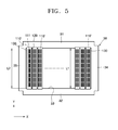
- FIG. 7 is a cross-sectional view taken along line I-I of a unit mask of FIG. 6.
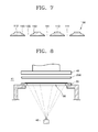
- FIG. 8 is a cross sectional view showing an apparatus for depositing an organic film on a substrate.
- FIG. 9 is a plan view showing a pixel pattern of an OLED device according to an embodiment of the present invention.
- FIG. 10 is a cross-sectional view of a passive matrix OLED device according to an embodiment of the present invention.
- FIG. 11 is a cross-sectional view of an active matrix OLED device according to an embodiment of the present invention.
- FIG. 4 is an exploded perspective view showing a mask frame assembly for depositing a thin film of an OLED device according to an embodiment ofthe present invention
- FIG. 5 is a plan view of the mask frame assembly of FIG. 4.
- the mask frame assembly comprises a frame 30 and unit masks 110 and 110', and the frame 30 supports both ends of the unit masks 110 and 110'.
- the unit masks 110 and 110' constitute a mask 100, where unit masks 110' denote outermost unit masks of the mask 100.
- the frame 30 includes first supporting units 31 and 32 arranged substantially parallel to each other and second supporting units 34 and 35 that form a rectangular opening 33 by connecting to ends of the first supporting units 31 and 32.
- the second supporting units 34 and 35 are arranged substantially parallel to the unit masks 110 and 110' and may be formed of an elastic material, but are not limited thereto.
- the first supporting units 31 and 32 and the second supporting units 34 and 35 maybe formed in one body.
- the frame 30 is strong enough to support the unit masks 110 and 110'.
- the frame 30 may have any structure that does not interrupt the adherence between a material to be deposited and the mask.
- the mask 100 includes at least two unit masks 110 and 110'.
- Each unit mask 110 and 110' is formed in a thin film strip, and deposition openings 111 are formed in a length direction of the unit masks 110 and 110' at a predetermined distance from each other.
- the mask 100 composes a masking pattern by the deposition openings 111. That is, each deposition opening 111 has a size corresponding to the size of a sub-pixel. As FIG. 4 and FIG. 5 show, the deposition openings 111 may be a discontinuous dot pattern, or, although not shown, a continuous stripe pattern.
- the unit masks 110 and 110' may be a magnetic thin film formed of nickel or a nickel alloy. Further, the unit masks may be formed of a nickel-cobalt alloy which has a good surface roughness and may be easily formed in a fine pattern.
- the fine patterning and superior surface flatness of the unit masks 110 and 110' may be obtained by forming the deposition openings 111 using an electro forming method. Also, the fine patterning and superior surface flatness of the unit masks 110 and 110' may be obtained by etching a thin film on which a resist layer having an identical pattern to the deposition openings 111 using a photoresist is formed or a film having an identical pattern to the deposition opening 111 is attached.
- Both ends of the unit masks 110 and 110' may be bonded or welded to the frame 30 while applying tension in the Y axis direction of FIG. 4. At this time, the deposition openings 111 for depositing of the unit masks 110 and 110' are located within the openings 33.
- the unit masks 110 and 110' and the frame 30 may be bonded by an adhesive or welded using laser welding or resist heated welding, but laser welding may be preferred given its precision.
- a first gap 120 exists between the unit masks 110 and 110'.
- a width W1 of the first gap 120 is substantially equal to the width W2 ofthe deposition openings 111 of the unit mask 110. Accordingly, the product to be deposited may be patterned by the first gap 120 to have substantially the same width as that patterned by the openings 111.
- FIG. 6 is a plan view showing sub-pixels of the OLED device formed using the mask frame assembly of FIG. 4.
- a plurality of sub-pixels 210 of a single color may be deposited. Therefore, when the sub-pixels 210 have red, green, and blue color, one deposition opening 111 corresponds to one sub-pixel 210.
- a product to be deposited may be patterned by the first gap 120 to have the same width as that patterned by the deposition openings 111.
- a width W1 of the first gap 120 equals the width W2 of the deposition openings 111.
- a cross-sectional structure of the first gap 120 is the same as a cross-sectional structure of the deposition openings 111 as shown in FIG. 7, which is a cross-sectional view of the mask 100 taken along line I-I of FIG. 6.
- a lower part of the mask 100 indicates a portion to which a substrate is closely adhered and an upper part of the mask 100 indicate portions at which deposition vapors arrive from a deposition source.
- a sloped taper is formed on a shielding part to reduce a shadow effect.
- a sloped taper is formed on shielding parts 112. The same taper is formed on end parts 113, which are vertical to the length direction of the unit mask 110, so that the deposition openings 111 and the first gap 120 have the same cross-sectional structure.
- the first gap 120 extends along a length direction of the unit mask 110.
- the length L1 of the first gap 120 may substantially equal a length of the unit mask 110 exposed in the opening 33 of the frame 30. That is, as shown in FIG. 5, a distance between the first supporting units 31 and 32 facing each other may be substantially equal to the length L1 of the first gap 120.
- a second gap 130 may be located between each outermost unit mask 110' and the frame 30.
- the second gap 130 may also be used to deposit the sub-pixels 210. Therefore, even though it is not shown in the drawing, the second gap 130 may have substantially the same width and cross-sectional structure as the deposition openings 111.
- the second gap 130 extends along the length direction of the unit mask 110'.
- the length L2 of the second gap 130 may be substantially equal to the length of the unit mask 110' exposed in the opening 33 of the frame 30. That is, as shown in FIG. 5, a distance between the first supporting units 31 and 32 facing each other may be substantially equal to the length L2 of the second gap 130.
- Deposition may be performed with the mask frame assembly for depositing a thin film according to an embodiment of the present invention by mounting it on a deposition apparatus shown in FIG. 8.
- a mask frame assembly is mounted on a side corresponding to an organic film deposition crucible 42 disposed in a vacuum chamber 41, and a substrate 220 on which a thin film will be formed is arranged on the mask frame assembly.
- the mask 100 is closely adhered to the substrate 220 by driving a magnet unit 43.
- An organic material placed on the organic film deposition crucible 42 may be vaporized by driving the organic film deposition crucible 42 and deposited on the substrate 220.
- FIG. 9 is a plan view showing a pixel pattern of an OLED device 200 formed by deposition.
- the sub-pixels 210 of the OLED device 200 may include at least one stripe pattern 211 and a plurality of dot patterns 212.
- a plurality of stripe patterns 211 separated a predetermined distance from each other may be formed, and the dot patterns 212 may be disposed between the stripe patterns 211.
- the stripe patterns 211 may include a red stripe pattern 211R, a green stripe pattern 211G, and a blue stripe pattern 211B
- the dot patterns 212 may include a red dot pattern 212R, a green dot pattern 212G, and a blue dot pattern 212B.
- the red stripe pattern 211R, the green stripe pattern 211G, and the blue stripe pattern 211B are arranged adjacent to each other, and groups of the red, green, and blue stripe patterns may be arranged repeatedly.
- the dot patterns 212 are arranged between the grouped stripe patterns 211.
- Forming the sub-pixels 210 in this pattern may provide a very high precision pitch between pixels because the mask frame has high pitch precision for depositing. Therefore, a high quality display device may be manufactured since the pitch precision between the pixels is high even with a large scale display device.
- the OLED device may be a passive matrix or active matrix device.
- FIG. 10 is a cross-sectional view showing a passive matrix OLED device in which a first electrode layer 221 is formed in a stripe pattern on a glass substrate 220, and an organic layer 226 and a second electrode layer 227 are sequentially formed on the first electrode layer 221.
- An insulating layer 222 may be interposed between the first electrodes 221, and the second electrode layer 227 maybe formed in a pattern crossing the first electrode layer 221.
- the organic layer 226 may be a low molecular weight organic layer or a polymer layer. If formed as a low molecular weight organic layer, a first organic layer 223, such as a Hole Injection Layer (HIL) and/or a Hole Transport Layer (HTL), an Emission Layer (EML) 224, and a second organic layer 225, such as an Electron Transport Layer (ETL) and/or an Electron Injection Layer (EIL), may be stacked in a single structure or a composite structure.
- HIL Hole Injection Layer
- HTL Hole Transport Layer
- EML Emission Layer
- EIL Electron Transport Layer
- EIL Electron Transport Layer
- the organic material may be copper phthalocyanine (CuPc), N,N'-Di(naphthalene-1-yl)-N,N'-diphenyl-benzidine (NPB), or tris-8-hydroxyquinoline aluminum (Alq3).
- CuPc copper phthalocyanine
- NPB N,N'-Di(naphthalene-1-yl)-N,N'-diphenyl-benzidine
- Alq3 tris-8-hydroxyquinoline aluminum
- the organic layer 226 is formed of a polymer organic film, it may have a structure including the first organic layer 223, having a HTL, and the EML 224, and at this time, the second organic layer 225 may not be used.
- the HTL can be formed of PEDOT and the EML can be formed of Poly-Phenylenevinylene (PPV) and Polyfluorene.
- the polymer organic film may be formed by various methods including a screen printing method or an ink jet printing method.
- the EML 224 of the organic layer 226 can emit the full color spectrum since it includes red R, green G, and blue B colors, and can form a pattern as shown in FIG. 9. Therefore, a high quality image may be displayed since the pattern has a high precision pitch.
- the first electrode layer 221 may function as an anode, and the second electrode layer 227 may function as a cathode. Alternatively, the polarity of the first electrode layer 221 and the second electrode layer 227 may be reversed.
- the first electrode layer 221 may be a transparent electrode or a reflection electrode.
- the first electrode layer 221 may be formed of ITO, IZO, ZnO or In 2 O 3
- it may be formed of ITO, IZO, ZnO or In 2 O 3 on a reflection film ofAg, Mg, Al, Pt, Pd, Au, Ni, Nd, Ir, Cr, or a compound of these metals.
- the second electrode layer 227 may also be a transparent electrode or a reflection electrode.
- an auxiliary electrode layer or a bus electrode line may be formed of a material for forming the transparent electrode, such as ITO, IZO, ZnO, or InO 3 , on the intermediate layer.
- the second electrode layer 227 is a reflection electrode, it may be formed by entirely depositing Li, Ca, LiF/Ca, LiF/Al, Al, Ag, Mg, or a compound of these metals.
- the OLED device is sealed to prevent oxygen or moisture penetration.
- FIG. 11 is a cross-sectional view showing an active matrix OLED device according to an embodiment of the present invention.
- the sub-pixels in FIG. 11 include at least one thin film transistor (TFT) and an electroluminescent (EL) device (OLED device) which is a self emissive device.
- TFT thin film transistor
- EL electroluminescent
- the structure of the TFT is not limited to the structure shown in FIG. 11, as it may have various forms.
- the active matrix OLED device will now be described.
- a buffer layer 230 which may be formed of SiO 2 or SiNx, is formed on a glass substrate 220, and a TFT is arranged on the buffer layer 230.
- the TFT includes a semiconductor active layer 231 formed on the buffer layer 230, a gate insulating film 232 covering the semiconductor active layer 231, and a gate electrode 233 formed on the gate insulating film 232.
- An interlayer insulating layer 234 covers the gate electrode 233, and source and drain electrodes 235 are formed on the interlayer insulating layer 234.
- the source and drain electrodes 235 contact a source region and a drain region, respectively, of the semiconductor active layer 231 through contact holes formed in the gate insulating film 232 and the interlayer insulating layer 234.
- the semiconductor active layer 231 may be formed of an inorganic semiconductor or an organic semiconductor, and it includes a channel region that connects the source region and the drain region.
- the source region and the drain region ofthe semiconductor active layer 231 may be doped by an n-type or p-type dopant.
- the inorganic semiconductor for forming the semiconductor active layer 231 may include, for example, CdS, GaS, ZnS, CdSe, CaSe, ZnSe, CdTe, SiC, and Si.
- the organic semiconductor for forming the semiconductor active layer 231 may include, for example, organic semiconductor materials having a band gap of 1-4 eV, such as, polymers ofpolythiophene and its derivatives, polyparaphenylenevinylene and its derivatives, polyparaphenylene and its derivatives, polyflorene and its derivatives, polythiophenevinylene and its derivatives, polythiophene-heterocyclic aromatic polymeric and its derivatives, and low molecular weight molecules ofpentacene, tetracene, alpha-6-thiophene, oligoacene of naphthalene and its derivatives, alpha-5-thiophene oligothiophene and its derivatives, phthalocyanine that does not include a metal and its derivatives, pyromelitic dianhydride and its derivatives, pyromelitic diimide and its derivatives, perylenetetracarboxylic acid dianhydride and its derivatives, and perylenetetracar
- the gate insulating film 232 may be formed of SiO 2 , SiNx, or a double film of SiO 2 and SiNx.
- the gate electrode 233 is formed of a conductive material, such as MoW, Al, Cr, Al/Cu, or a conductive polymer.
- a region on the gate insulating film 232 in which the gate electrode 233 is formed corresponds to the channel region ofthe semiconductor active layer 231.
- the interlayer insulating layer 234 maybe formed of SiO 2 , SiNx, or a compound of these materials, and the source and drain electrodes 235 may be formed of the same material forming the gate electrode 233.
- At least one capacitor is coupled to the TFT.
- the first electrode layer 221 which functions as an anode ofan OLED device, is coupled to one ofthe source and drain electrodes 235.
- the first electrode layer 221 is formed on the planarizing film 237, and a pixel defining layer 238 covering the first electrode layer 221 is formed on the planarizing film 237. After forming a predetermined opening in the pixel defining layer 238 to expose a portion of the first electrode layer 221, an OLED device is formed.
- the OLED device displays a predetermined image by emitting red, green, or blue light according to the current flow, and it includes the first electrode layer 221 that receives a positive voltage from the source or drain electrode 235, a second electrode layer 227 that supplies negative power and covers the pixels, and an organic layer 226 arranged between the first electrode layer 221 and the second electrode layer 227 to emit light.
- a high precision display device may be realized by arranging the EML 224 of the organic layer 226 as the pixels disposed in FIG. 9.
- the first electrode layer 221 may be formed of a transparent electrode or a reflective electrode, like the passive matrix OLED, to correspond to the opening shape of each sub-pixel.
- the second electrode layer 227 may be formed by depositing a transparent electrode or a reflective electrode on the entire surface of the display region. Alternatively, the second electrode layer 227 may be formed in various patterns. The positions of the first electrode layer 221 and the second electrode layer 227 may be reversed.
- the OLED device is sealed to prevent oxygen or moisture penetration.
- the mask frame assembly for depositing a thin film may increase the precision of a total pitch of a pattern of the masking pattern unit and may reduce the deformation of the pattern due to heat.
- the deposition on a large display area may be possible since gaps between the unit masks may be used as a pattern.
- a display device manufactured using the mask frame assembly may provide a high precision pitch between the pixels and display a high quality image.
Landscapes
- Chemical & Material Sciences (AREA)
- Engineering & Computer Science (AREA)
- Manufacturing & Machinery (AREA)
- Chemical Kinetics & Catalysis (AREA)
- Materials Engineering (AREA)
- Mechanical Engineering (AREA)
- Metallurgy (AREA)
- Organic Chemistry (AREA)
- Electroluminescent Light Sources (AREA)
- Physical Vapour Deposition (AREA)
Applications Claiming Priority (1)
| Application Number | Priority Date | Filing Date | Title |
|---|---|---|---|
| KR1020040055074A KR100659057B1 (ko) | 2004-07-15 | 2004-07-15 | 박막 증착용 마스크 프레임 조립체 및 유기 전계 발광표시장치 |
Publications (3)
| Publication Number | Publication Date |
|---|---|
| EP1626103A2 true EP1626103A2 (de) | 2006-02-15 |
| EP1626103A3 EP1626103A3 (de) | 2006-08-30 |
| EP1626103B1 EP1626103B1 (de) | 2009-10-28 |
Family
ID=35058632
Family Applications (1)
| Application Number | Title | Priority Date | Filing Date |
|---|---|---|---|
| EP05106299A Expired - Lifetime EP1626103B1 (de) | 2004-07-15 | 2005-07-11 | Lochmasken-Rahmenanordnung für die Abscheidung von dünnen Schichten und mittels dieser Anordnung hergestellte organische lichtemittierende Anzeigevorrichtung |
Country Status (7)
| Country | Link |
|---|---|
| US (1) | US7802537B2 (de) |
| EP (1) | EP1626103B1 (de) |
| JP (1) | JP4428533B2 (de) |
| KR (1) | KR100659057B1 (de) |
| CN (1) | CN100484348C (de) |
| AT (1) | ATE447051T1 (de) |
| DE (1) | DE602005017335D1 (de) |
Cited By (2)
| Publication number | Priority date | Publication date | Assignee | Title |
|---|---|---|---|---|
| US9604245B2 (en) | 2008-06-13 | 2017-03-28 | Kateeva, Inc. | Gas enclosure systems and methods utilizing an auxiliary enclosure |
| CN110724928A (zh) * | 2019-11-20 | 2020-01-24 | 京东方科技集团股份有限公司 | 掩膜板 |
Families Citing this family (65)
| Publication number | Priority date | Publication date | Assignee | Title |
|---|---|---|---|---|
| US8128753B2 (en) | 2004-11-19 | 2012-03-06 | Massachusetts Institute Of Technology | Method and apparatus for depositing LED organic film |
| US8986780B2 (en) | 2004-11-19 | 2015-03-24 | Massachusetts Institute Of Technology | Method and apparatus for depositing LED organic film |
| US8138075B1 (en) | 2006-02-06 | 2012-03-20 | Eberlein Dietmar C | Systems and methods for the manufacture of flat panel devices |
| JP4677363B2 (ja) * | 2006-04-07 | 2011-04-27 | 九州日立マクセル株式会社 | 蒸着マスクおよびその製造方法 |
| KR100739309B1 (ko) * | 2006-10-13 | 2007-07-12 | 삼성에스디아이 주식회사 | 박막 증착용 마스크 및 이를 이용한 유기 전계발광표시장치 |
| CN101754859B (zh) * | 2007-06-14 | 2012-05-30 | 麻省理工学院 | 用于沉积膜的方法和设备 |
| US8556389B2 (en) | 2011-02-04 | 2013-10-15 | Kateeva, Inc. | Low-profile MEMS thermal printhead die having backside electrical connections |
| US11975546B2 (en) | 2008-06-13 | 2024-05-07 | Kateeva, Inc. | Gas enclosure assembly and system |
| US8899171B2 (en) | 2008-06-13 | 2014-12-02 | Kateeva, Inc. | Gas enclosure assembly and system |
| US10442226B2 (en) | 2008-06-13 | 2019-10-15 | Kateeva, Inc. | Gas enclosure assembly and system |
| US12064979B2 (en) | 2008-06-13 | 2024-08-20 | Kateeva, Inc. | Low-particle gas enclosure systems and methods |
| US8383202B2 (en) | 2008-06-13 | 2013-02-26 | Kateeva, Inc. | Method and apparatus for load-locked printing |
| US12018857B2 (en) | 2008-06-13 | 2024-06-25 | Kateeva, Inc. | Gas enclosure assembly and system |
| US10434804B2 (en) | 2008-06-13 | 2019-10-08 | Kateeva, Inc. | Low particle gas enclosure systems and methods |
| US9048344B2 (en) | 2008-06-13 | 2015-06-02 | Kateeva, Inc. | Gas enclosure assembly and system |
| US20100188457A1 (en) * | 2009-01-05 | 2010-07-29 | Madigan Connor F | Method and apparatus for controlling the temperature of an electrically-heated discharge nozzle |
| KR101117645B1 (ko) * | 2009-02-05 | 2012-03-05 | 삼성모바일디스플레이주식회사 | 마스크 조립체 및 이를 이용한 평판표시장치용 증착 장치 |
| KR101202346B1 (ko) * | 2009-04-16 | 2012-11-16 | 삼성디스플레이 주식회사 | 박막 증착용 마스크 프레임 조립체, 그 제조 방법 및 유기 발광 표시 장치의 제조 방법 |
| EP2425470A2 (de) * | 2009-05-01 | 2012-03-07 | Kateeva, Inc. | Verfahren und vorrichtung für organischen dampfstrahldruck |
| US9174250B2 (en) * | 2009-06-09 | 2015-11-03 | Samsung Display Co., Ltd. | Method and apparatus for cleaning organic deposition materials |
| US8802200B2 (en) * | 2009-06-09 | 2014-08-12 | Samsung Display Co., Ltd. | Method and apparatus for cleaning organic deposition materials |
| KR101182439B1 (ko) * | 2010-01-11 | 2012-09-12 | 삼성디스플레이 주식회사 | 박막 증착용 마스크 프레임 조립체 및 이를 이용한 유기 발광 표시장치의 제조방법 |
| KR101309864B1 (ko) * | 2010-02-02 | 2013-09-16 | 엘지디스플레이 주식회사 | 마스크 어셈블리 |
| KR101182239B1 (ko) * | 2010-03-17 | 2012-09-12 | 삼성디스플레이 주식회사 | 마스크 및 이를 포함하는 마스크 조립체 |
| KR101058117B1 (ko) * | 2010-03-22 | 2011-08-24 | 삼성모바일디스플레이주식회사 | 박막 증착용 마스크 어셈블리와, 이를 이용한 유기 발광 장치와, 이의 제조 방법 |
| KR101784467B1 (ko) * | 2011-01-10 | 2017-10-12 | 삼성디스플레이 주식회사 | 분할 마스크 및 그것을 이용한 마스크 프레임 조립체의 조립방법 |
| KR101693578B1 (ko) * | 2011-03-24 | 2017-01-10 | 삼성디스플레이 주식회사 | 증착 마스크 |
| WO2012138366A1 (en) | 2011-04-08 | 2012-10-11 | Kateeva, Inc. | Method and apparatus for printing using a facetted drum |
| KR101820020B1 (ko) * | 2011-04-25 | 2018-01-19 | 삼성디스플레이 주식회사 | 박막 증착용 마스크 프레임 어셈블리 |
| KR101813549B1 (ko) * | 2011-05-06 | 2018-01-02 | 삼성디스플레이 주식회사 | 분할 마스크와 그 분할 마스크를 포함한 마스크 프레임 조립체의 조립장치 |
| KR101931770B1 (ko) | 2011-11-30 | 2018-12-24 | 삼성디스플레이 주식회사 | 마스크 조립체 및 유기 발광 표시장치 |
| CN203666124U (zh) * | 2011-12-22 | 2014-06-25 | 科迪华公司 | 气体封闭系统 |
| CN102522323A (zh) * | 2011-12-28 | 2012-06-27 | 华南理工大学 | 一种ito图案化方法 |
| KR20130081528A (ko) * | 2012-01-09 | 2013-07-17 | 삼성디스플레이 주식회사 | 증착 마스크 및 이를 이용한 증착 설비 |
| CN103225059A (zh) * | 2012-01-30 | 2013-07-31 | 群康科技(深圳)有限公司 | 阴影掩膜及其补偿设计方法 |
| TWI480398B (zh) * | 2012-01-30 | 2015-04-11 | Innocom Tech Shenzhen Co Ltd | 陰影罩幕及其補償設計方法 |
| US9409209B2 (en) * | 2012-05-25 | 2016-08-09 | Derrick Corporation | Injection molded screening apparatuses and methods |
| US11161150B2 (en) | 2012-05-25 | 2021-11-02 | Derrick Corporation | Injection molded screening apparatuses and methods |
| CN102766844B (zh) * | 2012-08-10 | 2014-10-22 | 深圳市华星光电技术有限公司 | 有机电致发光二极管有机材料蒸镀用掩模装置 |
| US20140041586A1 (en) * | 2012-08-10 | 2014-02-13 | Shenzhen China Star Optoelectronics Technology Co., Ltd. | Masking Device for Vapor Deposition of Organic Material of Organic Electroluminescent Diode |
| CN102776473B (zh) * | 2012-08-10 | 2014-10-29 | 深圳市华星光电技术有限公司 | 有机电致发光二极管有机材料蒸镀用掩模装置 |
| KR20140057852A (ko) * | 2012-11-05 | 2014-05-14 | 삼성디스플레이 주식회사 | 유기 발광 표시 장치 및 유기 발광 표시 장치의 제조 방법 |
| KR101980232B1 (ko) | 2012-11-14 | 2019-05-21 | 삼성디스플레이 주식회사 | 패터닝 슬릿 시트 프레임 어셈블리 |
| KR102100446B1 (ko) | 2012-12-10 | 2020-04-14 | 삼성디스플레이 주식회사 | 박막 증착용 마스크 조립체 및 이의 제조 방법 |
| DE102013101586A1 (de) | 2013-02-18 | 2014-08-21 | Aixtron Se | Mehrschichtige Schattenmaske |
| KR102072679B1 (ko) * | 2013-02-27 | 2020-02-04 | 삼성디스플레이 주식회사 | 박막 증착용 마스크 어셈블리 제조 방법 |
| KR20140109699A (ko) * | 2013-03-06 | 2014-09-16 | 삼성디스플레이 주식회사 | 마스크 구조체와 이를 포함하는 마스크 조립체 및 마스크 구조체 제조방법 |
| KR102162790B1 (ko) * | 2013-05-02 | 2020-10-08 | 삼성디스플레이 주식회사 | 마스크 프레임 조립체용 용접기 |
| JP2015069806A (ja) * | 2013-09-27 | 2015-04-13 | 株式会社ジャパンディスプレイ | 有機エレクトロルミネッセンス表示装置の製造方法 |
| WO2015100375A1 (en) | 2013-12-26 | 2015-07-02 | Kateeva, Inc. | Thermal treatment of electronic devices |
| WO2015112454A1 (en) | 2014-01-21 | 2015-07-30 | Kateeva, Inc. | Apparatus and techniques for electronic device encapsulation |
| KR102850075B1 (ko) | 2014-04-30 | 2025-08-25 | 카티바, 인크. | 가스 쿠션 장비 및 기판 코팅 기술 |
| KR102330330B1 (ko) * | 2014-12-16 | 2021-11-25 | 삼성디스플레이 주식회사 | 마스크 프레임 조립체 및 그 제조방법 |
| KR102352280B1 (ko) * | 2015-04-28 | 2022-01-18 | 삼성디스플레이 주식회사 | 마스크 프레임 조립체 제조 장치 및 이를 이용한 마스크 프레임 조립체 제조 방법 |
| KR20170030685A (ko) * | 2015-09-09 | 2017-03-20 | 삼성디스플레이 주식회사 | 증착용 마스크 및 그 제조 방법 |
| KR102549358B1 (ko) * | 2015-11-02 | 2023-06-29 | 삼성디스플레이 주식회사 | 증착 마스크 조립체 및 이를 이용한 표시 장치의 제조 방법 |
| KR102608420B1 (ko) * | 2016-03-09 | 2023-12-01 | 삼성디스플레이 주식회사 | 증착용 마스크, 표시 장치의 제조 장치 및 표시 장치의 제조 방법 |
| KR102691002B1 (ko) * | 2016-11-30 | 2024-08-05 | 엘지디스플레이 주식회사 | 증착용 마스크 및 그 제조방법 |
| KR101963982B1 (ko) * | 2017-12-27 | 2019-03-29 | 캐논 톡키 가부시키가이샤 | 성막 장치, 성막 방법, 및 전자 디바이스의 제조 방법 |
| CN108251796B (zh) * | 2018-01-31 | 2020-11-27 | 京东方科技集团股份有限公司 | 一种精细金属掩膜板及其制备方法、掩膜集成框架 |
| CN109182964B (zh) * | 2018-08-31 | 2019-11-15 | 云谷(固安)科技有限公司 | 掩膜板排版方法 |
| CN110172666A (zh) * | 2019-06-13 | 2019-08-27 | 京东方科技集团股份有限公司 | 掩膜板组件及其制作方法、像素生成方法 |
| CN110931639A (zh) * | 2019-11-26 | 2020-03-27 | 武汉华星光电半导体显示技术有限公司 | 可提高像素分辨率的像素排列显示设备与蒸镀方法 |
| KR102787865B1 (ko) * | 2020-02-21 | 2025-04-01 | 삼성디스플레이 주식회사 | 표시 장치의 제조장치, 마스크 어셈블리의 제조방법, 및 표시 장치의 제조방법 |
| KR20230026596A (ko) | 2021-08-17 | 2023-02-27 | 삼성디스플레이 주식회사 | 표시패널 및 증착설비 |
Citations (13)
| Publication number | Priority date | Publication date | Assignee | Title |
|---|---|---|---|---|
| US3241519A (en) | 1962-04-05 | 1966-03-22 | Western Electric Co | Tensioned and cooled mask |
| JP2000012238A (ja) | 1998-06-29 | 2000-01-14 | Futaba Corp | 有機el素子、有機el素子製造用マスク及び有機el素子の製造方法 |
| KR20000060589A (ko) | 1999-03-17 | 2000-10-16 | 구자홍 | 풀-컬러 유기 el 디스플레이 패널 및 그 제조방법 |
| JP2001247961A (ja) | 2000-03-06 | 2001-09-14 | Casio Comput Co Ltd | 蒸着用スクリーンマスク、蒸着方法及び有機el素子の製造方法 |
| JP2001254169A (ja) | 2000-03-13 | 2001-09-18 | Optonix Seimitsu:Kk | 蒸着用金属マスクおよび蒸着用金属マスク製造方法 |
| JP2001273979A (ja) | 1994-12-13 | 2001-10-05 | Trustees Of Princeton Univ | オーガニック発光構造 |
| US20020025406A1 (en) | 2000-08-25 | 2002-02-28 | Nec Corporation | Metal mask structure and method for maufacturing thereof |
| EP1209522A2 (de) | 2000-11-28 | 2002-05-29 | Lg Electronics Inc. | Maske zur herstellung von Bildschirmen |
| EP1229144A2 (de) | 2001-01-31 | 2002-08-07 | Toray Industries, Inc. | Integrierte Maske sowie Anlage und Verfahren zur Herstellung einer organischen elektroluminiszenten Vorrichtung unter Verwendung derselben |
| JP2002235165A (ja) | 2001-02-08 | 2002-08-23 | Sony Corp | マスク |
| KR100345972B1 (ko) | 1997-02-21 | 2002-10-25 | 닛본 덴기 가부시끼가이샤 | 유기전자발광표시장치및그제조방법 |
| KR20030046090A (ko) | 2001-12-05 | 2003-06-12 | 삼성 엔이씨 모바일 디스플레이 주식회사 | 유기 전자 발광 소자의 박막 증착용 마스크 프레임 조립체 |
| EP1584703A1 (de) | 2004-03-23 | 2005-10-12 | Seiko Epson Corporation | Mask, Verfahren zu seiner Herstellung, Verfahren zur Herstellung eines Dünnschichtmusters, Verfahren zur Herstellung einer elektro-optischen Vorrichtung und elektronisches Apparat |
Family Cites Families (15)
| Publication number | Priority date | Publication date | Assignee | Title |
|---|---|---|---|---|
| US3973965A (en) * | 1972-05-30 | 1976-08-10 | Tokyo Shibaura Electric Co., Ltd. | Making shadow mask with slit-shaped apertures for CRT |
| US5869929A (en) | 1997-02-04 | 1999-02-09 | Idemitsu Kosan Co., Ltd. | Multicolor luminescent device |
| JPH10319870A (ja) * | 1997-05-15 | 1998-12-04 | Nec Corp | シャドウマスク及びこれを用いたカラー薄膜el表示装置の製造方法 |
| JPH11260257A (ja) * | 1998-03-12 | 1999-09-24 | Sony Corp | 高精細度管用色選別マスクの製造方法 |
| JP3024641B1 (ja) * | 1998-10-23 | 2000-03-21 | 日本電気株式会社 | シャドウマスク及びその製造方法並びにシャドウマスクを用いた有機elディスプレイの製造方法 |
| US6579422B1 (en) | 1999-07-07 | 2003-06-17 | Sony Corporation | Method and apparatus for manufacturing flexible organic EL display |
| TW480722B (en) | 1999-10-12 | 2002-03-21 | Semiconductor Energy Lab | Manufacturing method of electro-optical device |
| JP2001237073A (ja) | 2000-02-24 | 2001-08-31 | Tohoku Pioneer Corp | 多面取り用メタルマスク及びその製造方法 |
| US6717342B2 (en) * | 2000-08-29 | 2004-04-06 | Lg Electronics Inc. | Shadow mask in color CRT |
| KR100647573B1 (ko) * | 2000-10-13 | 2006-11-17 | 삼성에스디아이 주식회사 | 칼라 음극선관용 텐션마스크 조립체 |
| JP2002220656A (ja) * | 2000-11-22 | 2002-08-09 | Sanyo Electric Co Ltd | 蒸着用マスクおよびその製造方法 |
| JP2003253434A (ja) * | 2002-03-01 | 2003-09-10 | Sanyo Electric Co Ltd | 蒸着方法及び表示装置の製造方法 |
| CN100464440C (zh) * | 2002-06-03 | 2009-02-25 | 三星移动显示器株式会社 | 用于有机电致发光装置的薄层真空蒸发的掩模框组件 |
| JP4309099B2 (ja) | 2002-06-21 | 2009-08-05 | 三星モバイルディスプレイ株式會社 | 有機電子発光素子用メタルマスク及びこれを利用した有機電子発光素子の製造方法 |
| JP4173722B2 (ja) | 2002-11-29 | 2008-10-29 | 三星エスディアイ株式会社 | 蒸着マスク、これを利用した有機el素子の製造方法及び有機el素子 |
-
2004
- 2004-07-15 KR KR1020040055074A patent/KR100659057B1/ko not_active Expired - Lifetime
-
2005
- 2005-07-08 US US11/176,282 patent/US7802537B2/en active Active
- 2005-07-11 AT AT05106299T patent/ATE447051T1/de not_active IP Right Cessation
- 2005-07-11 EP EP05106299A patent/EP1626103B1/de not_active Expired - Lifetime
- 2005-07-11 DE DE602005017335T patent/DE602005017335D1/de not_active Expired - Lifetime
- 2005-07-13 JP JP2005204259A patent/JP4428533B2/ja not_active Expired - Lifetime
- 2005-07-15 CN CNB2005100844383A patent/CN100484348C/zh not_active Expired - Lifetime
Patent Citations (13)
| Publication number | Priority date | Publication date | Assignee | Title |
|---|---|---|---|---|
| US3241519A (en) | 1962-04-05 | 1966-03-22 | Western Electric Co | Tensioned and cooled mask |
| JP2001273979A (ja) | 1994-12-13 | 2001-10-05 | Trustees Of Princeton Univ | オーガニック発光構造 |
| KR100345972B1 (ko) | 1997-02-21 | 2002-10-25 | 닛본 덴기 가부시끼가이샤 | 유기전자발광표시장치및그제조방법 |
| JP2000012238A (ja) | 1998-06-29 | 2000-01-14 | Futaba Corp | 有機el素子、有機el素子製造用マスク及び有機el素子の製造方法 |
| KR20000060589A (ko) | 1999-03-17 | 2000-10-16 | 구자홍 | 풀-컬러 유기 el 디스플레이 패널 및 그 제조방법 |
| JP2001247961A (ja) | 2000-03-06 | 2001-09-14 | Casio Comput Co Ltd | 蒸着用スクリーンマスク、蒸着方法及び有機el素子の製造方法 |
| JP2001254169A (ja) | 2000-03-13 | 2001-09-18 | Optonix Seimitsu:Kk | 蒸着用金属マスクおよび蒸着用金属マスク製造方法 |
| US20020025406A1 (en) | 2000-08-25 | 2002-02-28 | Nec Corporation | Metal mask structure and method for maufacturing thereof |
| EP1209522A2 (de) | 2000-11-28 | 2002-05-29 | Lg Electronics Inc. | Maske zur herstellung von Bildschirmen |
| EP1229144A2 (de) | 2001-01-31 | 2002-08-07 | Toray Industries, Inc. | Integrierte Maske sowie Anlage und Verfahren zur Herstellung einer organischen elektroluminiszenten Vorrichtung unter Verwendung derselben |
| JP2002235165A (ja) | 2001-02-08 | 2002-08-23 | Sony Corp | マスク |
| KR20030046090A (ko) | 2001-12-05 | 2003-06-12 | 삼성 엔이씨 모바일 디스플레이 주식회사 | 유기 전자 발광 소자의 박막 증착용 마스크 프레임 조립체 |
| EP1584703A1 (de) | 2004-03-23 | 2005-10-12 | Seiko Epson Corporation | Mask, Verfahren zu seiner Herstellung, Verfahren zur Herstellung eines Dünnschichtmusters, Verfahren zur Herstellung einer elektro-optischen Vorrichtung und elektronisches Apparat |
Cited By (2)
| Publication number | Priority date | Publication date | Assignee | Title |
|---|---|---|---|---|
| US9604245B2 (en) | 2008-06-13 | 2017-03-28 | Kateeva, Inc. | Gas enclosure systems and methods utilizing an auxiliary enclosure |
| CN110724928A (zh) * | 2019-11-20 | 2020-01-24 | 京东方科技集团股份有限公司 | 掩膜板 |
Also Published As
| Publication number | Publication date |
|---|---|
| CN100484348C (zh) | 2009-04-29 |
| JP4428533B2 (ja) | 2010-03-10 |
| JP2006032342A (ja) | 2006-02-02 |
| KR20060006177A (ko) | 2006-01-19 |
| US7802537B2 (en) | 2010-09-28 |
| KR100659057B1 (ko) | 2006-12-21 |
| EP1626103B1 (de) | 2009-10-28 |
| CN1722918A (zh) | 2006-01-18 |
| DE602005017335D1 (de) | 2009-12-10 |
| ATE447051T1 (de) | 2009-11-15 |
| US20060012290A1 (en) | 2006-01-19 |
| EP1626103A3 (de) | 2006-08-30 |
Similar Documents
| Publication | Publication Date | Title |
|---|---|---|
| EP1626103B1 (de) | Lochmasken-Rahmenanordnung für die Abscheidung von dünnen Schichten und mittels dieser Anordnung hergestellte organische lichtemittierende Anzeigevorrichtung | |
| EP2159299B1 (de) | Maske zur Dünnfilmablagerung und Verfahren zur OLED-Herstellung damit | |
| US8604489B2 (en) | Mask frame assembly for thin layer deposition and method of manufacturing organic light emitting display device by using the mask frame assembly | |
| CN102760842B (zh) | 用于薄膜沉积的掩模框架组件 | |
| US8746169B2 (en) | Mask frame assembly for thin film deposition | |
| US8933450B2 (en) | Organic electro-luminescent display device | |
| EP2144292A2 (de) | Display aus organischen Leuchtdioden und dessen Herstellungsmethode | |
| US8729570B2 (en) | Mask frame assembly for thin film deposition, organic light-emitting display device using the same, and method of manufacturing the organic light-emitting display device | |
| KR100696523B1 (ko) | 박막 증착용 마스크 프레임 조립체 및 이를 이용한 유기발광 표시장치의 제조방법 | |
| KR20100119675A (ko) | 박막 증착용 마스크 프레임 조립체 및 이를 이용한 유기 발광 표시장치의 제조방법 | |
| KR100741138B1 (ko) | 박막 증착용 마스크 프레임 조립체 및 이를 이용한 유기발광 표시장치의 제조방법 | |
| KR100603398B1 (ko) | 증착용 마스크 및 전계발광 디스플레이 장치 | |
| KR100497094B1 (ko) | 하이브리드 구조 유기전계 발광소자 및 그의 제조방법 | |
| KR100759578B1 (ko) | 유기 발광 표시장치 및 그 제조방법 | |
| KR100927584B1 (ko) | 유기 발광 표시 장치 및 그 제조 방법 |
Legal Events
| Date | Code | Title | Description |
|---|---|---|---|
| PUAI | Public reference made under article 153(3) epc to a published international application that has entered the european phase |
Free format text: ORIGINAL CODE: 0009012 |
|
| AK | Designated contracting states |
Kind code of ref document: A2 Designated state(s): AT BE BG CH CY CZ DE DK EE ES FI FR GB GR HU IE IS IT LI LT LU LV MC NL PL PT RO SE SI SK TR |
|
| AX | Request for extension of the european patent |
Extension state: AL BA HR MK YU |
|
| PUAL | Search report despatched |
Free format text: ORIGINAL CODE: 0009013 |
|
| AK | Designated contracting states |
Kind code of ref document: A3 Designated state(s): AT BE BG CH CY CZ DE DK EE ES FI FR GB GR HU IE IS IT LI LT LU LV MC NL PL PT RO SE SI SK TR |
|
| AX | Request for extension of the european patent |
Extension state: AL BA HR MK YU |
|
| 17P | Request for examination filed |
Effective date: 20061103 |
|
| AKX | Designation fees paid |
Designated state(s): AT BE BG CH CY CZ DE DK EE ES FI FR GB GR HU IE IS IT LI LT LU LV MC NL PL PT RO SE SI SK TR |
|
| 17Q | First examination report despatched |
Effective date: 20080311 |
|
| RAP1 | Party data changed (applicant data changed or rights of an application transferred) |
Owner name: SAMSUNG MOBILE DISPLAY CO., LTD. |
|
| GRAP | Despatch of communication of intention to grant a patent |
Free format text: ORIGINAL CODE: EPIDOSNIGR1 |
|
| GRAS | Grant fee paid |
Free format text: ORIGINAL CODE: EPIDOSNIGR3 |
|
| GRAA | (expected) grant |
Free format text: ORIGINAL CODE: 0009210 |
|
| AK | Designated contracting states |
Kind code of ref document: B1 Designated state(s): AT BE BG CH CY CZ DE DK EE ES FI FR GB GR HU IE IS IT LI LT LU LV MC NL PL PT RO SE SI SK TR |
|
| REG | Reference to a national code |
Ref country code: GB Ref legal event code: FG4D |
|
| REG | Reference to a national code |
Ref country code: CH Ref legal event code: EP |
|
| REG | Reference to a national code |
Ref country code: IE Ref legal event code: FG4D |
|
| REF | Corresponds to: |
Ref document number: 602005017335 Country of ref document: DE Date of ref document: 20091210 Kind code of ref document: P |
|
| LTIE | Lt: invalidation of european patent or patent extension |
Effective date: 20091028 |
|
| NLV1 | Nl: lapsed or annulled due to failure to fulfill the requirements of art. 29p and 29m of the patents act | ||
| PG25 | Lapsed in a contracting state [announced via postgrant information from national office to epo] |
Ref country code: IS Free format text: LAPSE BECAUSE OF FAILURE TO SUBMIT A TRANSLATION OF THE DESCRIPTION OR TO PAY THE FEE WITHIN THE PRESCRIBED TIME-LIMIT Effective date: 20100228 Ref country code: SE Free format text: LAPSE BECAUSE OF FAILURE TO SUBMIT A TRANSLATION OF THE DESCRIPTION OR TO PAY THE FEE WITHIN THE PRESCRIBED TIME-LIMIT Effective date: 20091028 Ref country code: PT Free format text: LAPSE BECAUSE OF FAILURE TO SUBMIT A TRANSLATION OF THE DESCRIPTION OR TO PAY THE FEE WITHIN THE PRESCRIBED TIME-LIMIT Effective date: 20100301 Ref country code: ES Free format text: LAPSE BECAUSE OF FAILURE TO SUBMIT A TRANSLATION OF THE DESCRIPTION OR TO PAY THE FEE WITHIN THE PRESCRIBED TIME-LIMIT Effective date: 20100208 Ref country code: FI Free format text: LAPSE BECAUSE OF FAILURE TO SUBMIT A TRANSLATION OF THE DESCRIPTION OR TO PAY THE FEE WITHIN THE PRESCRIBED TIME-LIMIT Effective date: 20091028 Ref country code: LT Free format text: LAPSE BECAUSE OF FAILURE TO SUBMIT A TRANSLATION OF THE DESCRIPTION OR TO PAY THE FEE WITHIN THE PRESCRIBED TIME-LIMIT Effective date: 20091028 |
|
| PG25 | Lapsed in a contracting state [announced via postgrant information from national office to epo] |
Ref country code: CY Free format text: LAPSE BECAUSE OF FAILURE TO SUBMIT A TRANSLATION OF THE DESCRIPTION OR TO PAY THE FEE WITHIN THE PRESCRIBED TIME-LIMIT Effective date: 20091028 Ref country code: SI Free format text: LAPSE BECAUSE OF FAILURE TO SUBMIT A TRANSLATION OF THE DESCRIPTION OR TO PAY THE FEE WITHIN THE PRESCRIBED TIME-LIMIT Effective date: 20091028 Ref country code: PL Free format text: LAPSE BECAUSE OF FAILURE TO SUBMIT A TRANSLATION OF THE DESCRIPTION OR TO PAY THE FEE WITHIN THE PRESCRIBED TIME-LIMIT Effective date: 20091028 Ref country code: LV Free format text: LAPSE BECAUSE OF FAILURE TO SUBMIT A TRANSLATION OF THE DESCRIPTION OR TO PAY THE FEE WITHIN THE PRESCRIBED TIME-LIMIT Effective date: 20091028 |
|
| PG25 | Lapsed in a contracting state [announced via postgrant information from national office to epo] |
Ref country code: AT Free format text: LAPSE BECAUSE OF FAILURE TO SUBMIT A TRANSLATION OF THE DESCRIPTION OR TO PAY THE FEE WITHIN THE PRESCRIBED TIME-LIMIT Effective date: 20091028 Ref country code: BE Free format text: LAPSE BECAUSE OF FAILURE TO SUBMIT A TRANSLATION OF THE DESCRIPTION OR TO PAY THE FEE WITHIN THE PRESCRIBED TIME-LIMIT Effective date: 20091028 |
|
| PG25 | Lapsed in a contracting state [announced via postgrant information from national office to epo] |
Ref country code: EE Free format text: LAPSE BECAUSE OF FAILURE TO SUBMIT A TRANSLATION OF THE DESCRIPTION OR TO PAY THE FEE WITHIN THE PRESCRIBED TIME-LIMIT Effective date: 20091028 Ref country code: RO Free format text: LAPSE BECAUSE OF FAILURE TO SUBMIT A TRANSLATION OF THE DESCRIPTION OR TO PAY THE FEE WITHIN THE PRESCRIBED TIME-LIMIT Effective date: 20091028 Ref country code: DK Free format text: LAPSE BECAUSE OF FAILURE TO SUBMIT A TRANSLATION OF THE DESCRIPTION OR TO PAY THE FEE WITHIN THE PRESCRIBED TIME-LIMIT Effective date: 20091028 Ref country code: BG Free format text: LAPSE BECAUSE OF FAILURE TO SUBMIT A TRANSLATION OF THE DESCRIPTION OR TO PAY THE FEE WITHIN THE PRESCRIBED TIME-LIMIT Effective date: 20100128 |
|
| PG25 | Lapsed in a contracting state [announced via postgrant information from national office to epo] |
Ref country code: SK Free format text: LAPSE BECAUSE OF FAILURE TO SUBMIT A TRANSLATION OF THE DESCRIPTION OR TO PAY THE FEE WITHIN THE PRESCRIBED TIME-LIMIT Effective date: 20091028 Ref country code: CZ Free format text: LAPSE BECAUSE OF FAILURE TO SUBMIT A TRANSLATION OF THE DESCRIPTION OR TO PAY THE FEE WITHIN THE PRESCRIBED TIME-LIMIT Effective date: 20091028 |
|
| PLBE | No opposition filed within time limit |
Free format text: ORIGINAL CODE: 0009261 |
|
| STAA | Information on the status of an ep patent application or granted ep patent |
Free format text: STATUS: NO OPPOSITION FILED WITHIN TIME LIMIT |
|
| 26N | No opposition filed |
Effective date: 20100729 |
|
| PG25 | Lapsed in a contracting state [announced via postgrant information from national office to epo] |
Ref country code: GR Free format text: LAPSE BECAUSE OF FAILURE TO SUBMIT A TRANSLATION OF THE DESCRIPTION OR TO PAY THE FEE WITHIN THE PRESCRIBED TIME-LIMIT Effective date: 20100129 |
|
| PG25 | Lapsed in a contracting state [announced via postgrant information from national office to epo] |
Ref country code: MC Free format text: LAPSE BECAUSE OF NON-PAYMENT OF DUE FEES Effective date: 20100731 |
|
| REG | Reference to a national code |
Ref country code: CH Ref legal event code: PL |
|
| PG25 | Lapsed in a contracting state [announced via postgrant information from national office to epo] |
Ref country code: IT Free format text: LAPSE BECAUSE OF FAILURE TO SUBMIT A TRANSLATION OF THE DESCRIPTION OR TO PAY THE FEE WITHIN THE PRESCRIBED TIME-LIMIT Effective date: 20091028 |
|
| PG25 | Lapsed in a contracting state [announced via postgrant information from national office to epo] |
Ref country code: CH Free format text: LAPSE BECAUSE OF NON-PAYMENT OF DUE FEES Effective date: 20100731 Ref country code: LI Free format text: LAPSE BECAUSE OF NON-PAYMENT OF DUE FEES Effective date: 20100731 |
|
| PG25 | Lapsed in a contracting state [announced via postgrant information from national office to epo] |
Ref country code: IE Free format text: LAPSE BECAUSE OF NON-PAYMENT OF DUE FEES Effective date: 20100711 |
|
| REG | Reference to a national code |
Ref country code: DE Ref legal event code: R082 Ref document number: 602005017335 Country of ref document: DE Representative=s name: GULDE HENGELHAUPT ZIEBIG & SCHNEIDER, DE |
|
| PG25 | Lapsed in a contracting state [announced via postgrant information from national office to epo] |
Ref country code: LU Free format text: LAPSE BECAUSE OF NON-PAYMENT OF DUE FEES Effective date: 20100711 Ref country code: HU Free format text: LAPSE BECAUSE OF FAILURE TO SUBMIT A TRANSLATION OF THE DESCRIPTION OR TO PAY THE FEE WITHIN THE PRESCRIBED TIME-LIMIT Effective date: 20100429 Ref country code: NL Free format text: LAPSE BECAUSE OF FAILURE TO SUBMIT A TRANSLATION OF THE DESCRIPTION OR TO PAY THE FEE WITHIN THE PRESCRIBED TIME-LIMIT Effective date: 20091028 |
|
| PG25 | Lapsed in a contracting state [announced via postgrant information from national office to epo] |
Ref country code: TR Free format text: LAPSE BECAUSE OF FAILURE TO SUBMIT A TRANSLATION OF THE DESCRIPTION OR TO PAY THE FEE WITHIN THE PRESCRIBED TIME-LIMIT Effective date: 20091028 |
|
| REG | Reference to a national code |
Ref country code: DE Ref legal event code: R082 Ref document number: 602005017335 Country of ref document: DE Representative=s name: GULDE HENGELHAUPT ZIEBIG & SCHNEIDER, DE Effective date: 20120921 Ref country code: DE Ref legal event code: R081 Ref document number: 602005017335 Country of ref document: DE Owner name: SAMSUNG DISPLAY CO., LTD., KR Free format text: FORMER OWNER: SAMSUNG MOBILE DISPLAY CO. LTD., SUWON, KR Effective date: 20120921 Ref country code: DE Ref legal event code: R081 Ref document number: 602005017335 Country of ref document: DE Owner name: SAMSUNG DISPLAY CO., LTD., YONGIN-CITY, KR Free format text: FORMER OWNER: SAMSUNG MOBILE DISPLAY CO. LTD., SUWON, GYEONGGI, KR Effective date: 20120921 Ref country code: DE Ref legal event code: R082 Ref document number: 602005017335 Country of ref document: DE Representative=s name: GULDE & PARTNER PATENT- UND RECHTSANWALTSKANZL, DE Effective date: 20120921 |
|
| REG | Reference to a national code |
Ref country code: GB Ref legal event code: 732E Free format text: REGISTERED BETWEEN 20130110 AND 20130116 |
|
| REG | Reference to a national code |
Ref country code: FR Ref legal event code: TP Owner name: SAMSUNG MOBILE DISPLAY CO., LTD., KR Effective date: 20130220 |
|
| REG | Reference to a national code |
Ref country code: FR Ref legal event code: PLFP Year of fee payment: 12 |
|
| REG | Reference to a national code |
Ref country code: FR Ref legal event code: PLFP Year of fee payment: 13 |
|
| REG | Reference to a national code |
Ref country code: FR Ref legal event code: PLFP Year of fee payment: 14 |
|
| P01 | Opt-out of the competence of the unified patent court (upc) registered |
Effective date: 20230516 |
|
| PGFP | Annual fee paid to national office [announced via postgrant information from national office to epo] |
Ref country code: GB Payment date: 20240620 Year of fee payment: 20 |
|
| PGFP | Annual fee paid to national office [announced via postgrant information from national office to epo] |
Ref country code: FR Payment date: 20240624 Year of fee payment: 20 |
|
| PGFP | Annual fee paid to national office [announced via postgrant information from national office to epo] |
Ref country code: DE Payment date: 20240620 Year of fee payment: 20 |
|
| REG | Reference to a national code |
Ref country code: DE Ref legal event code: R071 Ref document number: 602005017335 Country of ref document: DE |
|
| REG | Reference to a national code |
Ref country code: GB Ref legal event code: PE20 Expiry date: 20250710 |