EP1626202A1 - Mécanisme de réduction de vitesse et unité d'entraînement avec un tel mécanisme - Google Patents
Mécanisme de réduction de vitesse et unité d'entraînement avec un tel mécanisme Download PDFInfo
- Publication number
- EP1626202A1 EP1626202A1 EP05017508A EP05017508A EP1626202A1 EP 1626202 A1 EP1626202 A1 EP 1626202A1 EP 05017508 A EP05017508 A EP 05017508A EP 05017508 A EP05017508 A EP 05017508A EP 1626202 A1 EP1626202 A1 EP 1626202A1
- Authority
- EP
- European Patent Office
- Prior art keywords
- bearing
- reduction gear
- drive element
- drive
- bearing rod
- Prior art date
- Legal status (The legal status is an assumption and is not a legal conclusion. Google has not performed a legal analysis and makes no representation as to the accuracy of the status listed.)
- Withdrawn
Links
- 230000009467 reduction Effects 0.000 title claims description 70
- 230000007246 mechanism Effects 0.000 title claims description 7
- 230000033001 locomotion Effects 0.000 claims abstract description 26
- 230000002093 peripheral effect Effects 0.000 claims abstract description 16
- 230000005540 biological transmission Effects 0.000 claims description 8
- 238000002347 injection Methods 0.000 claims description 7
- 239000007924 injection Substances 0.000 claims description 7
- 238000013016 damping Methods 0.000 claims description 4
- 230000008859 change Effects 0.000 claims description 3
- 238000005096 rolling process Methods 0.000 claims description 3
- 230000035515 penetration Effects 0.000 claims 1
- 238000003860 storage Methods 0.000 description 6
- 238000010276 construction Methods 0.000 description 5
- 238000004519 manufacturing process Methods 0.000 description 4
- 238000009434 installation Methods 0.000 description 3
- 239000000243 solution Substances 0.000 description 2
- 230000005355 Hall effect Effects 0.000 description 1
- 238000006073 displacement reaction Methods 0.000 description 1
- 230000008571 general function Effects 0.000 description 1
- 238000001746 injection moulding Methods 0.000 description 1
- 239000000463 material Substances 0.000 description 1
- 238000005259 measurement Methods 0.000 description 1
- 238000000034 method Methods 0.000 description 1
- 238000005406 washing Methods 0.000 description 1
- 238000004804 winding Methods 0.000 description 1
Images



Classifications
-
- F—MECHANICAL ENGINEERING; LIGHTING; HEATING; WEAPONS; BLASTING
- F16—ENGINEERING ELEMENTS AND UNITS; GENERAL MEASURES FOR PRODUCING AND MAINTAINING EFFECTIVE FUNCTIONING OF MACHINES OR INSTALLATIONS; THERMAL INSULATION IN GENERAL
- F16H—GEARING
- F16H1/00—Toothed gearings for conveying rotary motion
- F16H1/28—Toothed gearings for conveying rotary motion with gears having orbital motion
- F16H1/32—Toothed gearings for conveying rotary motion with gears having orbital motion in which the central axis of the gearing lies inside the periphery of an orbital gear
-
- Y—GENERAL TAGGING OF NEW TECHNOLOGICAL DEVELOPMENTS; GENERAL TAGGING OF CROSS-SECTIONAL TECHNOLOGIES SPANNING OVER SEVERAL SECTIONS OF THE IPC; TECHNICAL SUBJECTS COVERED BY FORMER USPC CROSS-REFERENCE ART COLLECTIONS [XRACs] AND DIGESTS
- Y10—TECHNICAL SUBJECTS COVERED BY FORMER USPC
- Y10T—TECHNICAL SUBJECTS COVERED BY FORMER US CLASSIFICATION
- Y10T74/00—Machine element or mechanism
- Y10T74/19—Gearing
Definitions
- the present invention relates to a reduction gear and in particular to a drive unit in which such a reduction gear is used.
- Reduction gears are used to convert a high input speed, as is typically provided by electric motors, to a lower output speed in order to be able to move certain masses by means of corresponding mechanisms.
- Reduction gears of smaller design are increasingly used in areas of automotive engineering, where they form part of servo motors, such as in window regulator motors, Wegverstellmotoren etc ..
- This rotational movement which is thereby greatly slowed down compared to the drive, can preferably be achieved via an outer toothing of the inner-wheel tire on an inner toothing of another, concentric with the support ring, but in contrast with this not stationary, but coaxially rotatable outer ring are transmitted, which is equipped with a rotatably mounted in the transmission housing output shaft.
- This elliptical deformation is transmitted by the fact that constantly teeth of the external teeth of the drive element with the internal teeth of the stationary support ring engage.
- the number of teeth of the outer toothing of the drive element is selected to be smaller than the number of teeth of the inner toothing of the support ring, there is a continuous rotation of the drive element relative to the stationary support ring, which is then transferred to the overlying Abtriebshohlrad with appropriate reduction.
- the output element is designed as a ring gear, which shell-like engages over the drive element and is provided on its surface with a central output shaft which is coaxial with the input shaft of the motor.
- the "shell-like" construction shown in this publication allows a particularly flat construction of the entire drive unit, so that this is preferably suitable for use in tight spaces.
- the essence of the invention is therefore that the arranged from a ring gear as the output element and arranged in this ring gear and acting together with this drive element reduction gear is constructed such that both the drive element and the output element together on a stationary and rotationally fixed bearing rod are stored.
- the axis about which all the components of the reduction gear build together and at least partially rotationally symmetrical, is arranged stationary.
- this bearing rod forms a part of the housing of the reduction gear or the drive unit containing this.
- the inventive design of the reduction gear allows easy mounting of all its components on the housing-fixed bearing rod, the individual components need only be placed on each other on the bearing rod.
- a central fixed axis simplifies the overall storage of the rotating components.
- the drive element is mounted eccentrically relative to the axis of rotation of the output element which coincides coaxially with the axis of the stationary and rotationally fixed bearing rod.
- the drive element has a smaller circumference than the driven element, that at least one circumferential section of the lateral surface of the drive element is in continuous contact with the inner surface of the driven element designed as a ring gear.
- the inner drive element in contrast to the previously described prior art, is not radially deformable, but rigid.
- At least one stationary bearing is provided according to the invention, in which the drive element is mounted with play.
- the game of this storage is chosen according to the invention so that the drive element when rolling its at least one peripheral portion of its lateral surface on the inner surface of the ring gear performs a so-called wobble about the axis of the stationary bearing rod.
- the drive element has a hub, in which a motor-driven eccentric, quasi the drive core, is slidably received.
- the eccentric itself is rotatably mounted about the axis of the stationary bearing rod. By the rotation of the eccentric about the bearing rod, the eccentricity is transmitted to the drive element, wherein the outer circumferential surface of the eccentric slidably displaces relative to the inner surface of the hub of the drive element.
- the drive element is non-rotatably arranged on a bearing plate opposite the ring gear, which is mounted horizontally movable and has an opening for a non-contact during the entire tumbling movement of the bearing rod.
- the horizontally movable mounting of the bearing plate is of course such that the play of the bearing also only such a horizontal movement of the drive member or the bearing plate permits, which allows a continuous circumferential section-wise rolling of the drive element in the ring gear.
- the drive element with the bearing plate in one piece, in particular as a plastic injection molded part is formed.
- the horizontally movable mounting of the bearing plate or the drive element located thereon is accomplished in a particular embodiment of the reduction gear according to the invention characterized in that the bearing plate has at its respective opposite corners four bearing pins, which are vertically away from the drive element parallel to the axis extend the stationary bearing rod and are received in correspondingly fixed locations provided bearing sleeves, wherein the storage is equipped with the necessary for the horizontal circular motion game.
- noise-reducing damping elements are provided between these two elements, either on the bearing sleeve or on the bearing journal.
- the wobbling movement performed by the drive element is then transmitted to the output element designed as a ring gear, which is rotatably mounted on the stationary bearing rod and therefore can perform exclusively a rotational movement.
- the output element On its side opposite the drive element side, the output element has a driven part, for example a pinion or a friction wheel, which then cooperates with a corresponding transmission element, for example a chain or a belt, of the mechanism to be driven by the reduction gear, wherein in an advantageous embodiment the output part and the output element in one piece, in particular formed as a plastic injection molded part.
- the driven-side ring gear can in this case overlap the drive element like a shell.
- the above-described construction of the reduction gear can be realized on the one hand via a non-positive or on the other hand via a positive connection.
- the drive element is designed as a friction wheel and the output element as a wheel tire, wherein the peripheral portion of the outer circumferential surface of the friction wheel rolls on the inner circumferential surface of the wheel tire in a continuous change.
- a corresponding reduction from the rotation of the motor-driven eccentric to be transmitted to the housing-fixed axis of the bearing rod rotatably mounted output-side ring gear.
- the drive element is designed as a gear and the output element as a ring gear with an internal toothing, wherein a peripheral portion of the gear meshes with the toothing of the ring gear.
- the desired reduction is accomplished in this embodiment over a predetermined difference in the number of teeth between the internal teeth of the ring gear and the external teeth of the gear.
- the inventive construction of the reduction gear is characterized in that an extremely flat structure can be realized.
- the number of components is reduced compared to the prior art solutions, which minimizes costs and permits cheap manufacture by the technique of plastic injection molding.
- the arrangement of all components on a fixed housing or fixed shaft also allows a very simple installation of all components.
- the use of the described reduction gear is provided in combination with a drive unit which also embodies the advantages realized by the invention in the reduction gear.
- the drive unit according to the invention in conjunction with the reduction gear according to the invention additionally has an electric motor, which consists of a rotor and a stator.
- the rotor is rotatably mounted on the stationary and rotationally fixed bearing rod. This way of storage also allows for such a drive unit easy installation with the realization of an extremely flat structure.
- the rotor is designed as an external rotor and engages over the stator like a shell. This makes it possible that the stator rotatably on the support plate, and that can be arranged around the bearing rod, which further increases the compactness of the structure.
- the cooperating with the rotor eccentric for the reduction gear can either be rotatably mounted as a separate component on the stationary bearing rod or rotatably connected to the surface of the shell-like rotor with this and preferably integrally formed with this, in particular as a plastic injection molded part.
- the support plate which has the bearing rod and the bearing sleeves stationary, can further receive the electronic control unit and optionally a sensor for the electric motor.
- the use of a brushless motor which operates quieter and allows control of the speed or a current control is suitable.
- This is particularly advantageous in the use of the drive unit according to the invention as, for example, window motor, since in the imminent danger of pinching fingers a quick reversal must be ensured, which can be technically easier and faster implement a brushless motor.
- the rotor of the electric motor in an embodiment of the drive unit according to the invention has a ring arranged in the interior of the shell-like rotor, which extends vertically beyond the outer circumferential surface of the rotor in the direction of the support plate whereby a ring exposed from the shell of the external rotor rotor is formed.
- the sensor system for this purpose can be constructed of Hall elements, which are then arranged on the support plate so that they face the exposed ring and realize on corresponding peripheral portions of the ring a speed measurement on the occurrence of the known Hall effects.
- the drive unit according to the invention is particularly suitable for use in the automotive sector, where the installation spaces are generally limited.
- the drive unit can be used as an adjusting motor in general for the adjustment of the vehicle seats, as a window motor or as a windscreen wiper motor.
- Other applications outside the automotive sector are of course also possible, where always only a small space is available and a corresponding reduction must be provided.
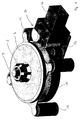
- Figure 1 shows schematically a cross section through a reduction gear 1 according to the present invention.
- the reduction gear 1 consists essentially of a drive element 2 and an output element. 3
- the drive element 2 is formed as a rigid, non-deformable gear with external teeth 4.
- the external toothing 4 of the toothed wheel 2 meshes via a peripheral portion with an internal toothing 5 of the output element 3, as can be seen in particular from FIGS. 2a to 2d.
- the output element 3 is accordingly designed as a ring gear, which engages over the gear 4 shell-like.
- the output member 6 is configured as a friction wheel, which can cooperate with a belt, for example.
- the gear 2 has a hub 7, which receives a motor-driven eccentric 8.
- the eccentric 8 is slidably received in the hub 7, i. it can rotate relative to the inner circumferential surface of the hub 7.
- the storage bar 9 itself is stationary, i. not rotating, for example, in a housing not shown here for the reduction gear 1, mounted.
- FIGS. 2a to 2d now show the movement carried out by the toothed wheel 2 with the aid of sectional representations through the reduction gear 1 according to the invention viewed from below, wherein the shading of the eccentric 8 has been omitted for better illustration.
- the gear 2 is arranged integrally on a bearing plate 10.
- the bearing plate 10 has at its respective corners bearing pin 11, which are mounted in housing-fixed bearing sleeves 12, as can be seen by way of example from Figures 4 to 6.
- the sprocket 2 has between its hub 7 and its outer teeth 4 spokes 13 in order to allow a certain weight saving with sufficient rigidity.
- the eccentric 8 has now rotated in the clockwise direction in the representation another 90 degrees, which slides within the hub 7 of the gear 2.
- This causes the tooth Z is no longer in engagement with the rotatably mounted Abtriebshohlrad 3 at its corresponding location. Rather, the peripheral portion of the gear 2 engaged with the internal teeth 5 also travels 90 degrees clockwise. This movement is also performed by the bearing pin 11 in the bearing sleeves 12.
- Figure 2c shows a further rotation of the eccentric 8 by 90 degrees clockwise.
- the peripheral portion which is in engagement with the internal toothing 5 of the ring gear 3, moves by 90 degrees in the clockwise direction. This movement is further performed, as can be seen in Figure 2d, until finally the tooth Z again comes into engagement with the internal toothing 5 of the ring gear 3.
- FIG. 3 shows by way of example a cross section through a drive unit 14 according to the invention, which has the reduction gear 1 in combination with an electric motor 15.
- the electric motor 15 consists of a rotor 16 and a stator 17th
- the rotor 16 is an external rotor and cup-like overlaps the stator 17, which has four coils 18 opposite one another.
- the coils 18 are, as shown in Figure 4, placed on a star-shaped stator core 19 and are surrounded by a circumferentially closed stator ring 20. This allows a simple assembly of the coils 18, which makes a separate winding of the stator cores 19 superfluous and allows a simple mounting of the entire stator 17 on the support rod 9 within the drive unit 14.
- the eccentric 8 is formed integrally with the cup-shaped rotor 16. Since the eccentric 8 engages directly in the hub 7 of the gear 2, thereby creating a very compact structure.
- the bearing rod 9 is rotatably received in a bearing bush 21.
- a bearing bush 21 Around the bearing bush 21 around the stator 17 of the electric motor 15 is arranged rotationally fixed.
- the bearing bush 21 for the bearing rod 9 is part of a support plate 22 and formed integrally therewith.
- the support plate 22 further has, as can be seen from the exploded view in Figure 4, the four bearing sleeves 12 of the reduction gear 1, in which the bearing pins 11 are received with play.
- a circuit board 23 can be arranged beyond an attachment to the bearing bush 21, on which the electronic control unit 24 and a sensor 25 and a power supply 26 for the electric motor 15 is arranged. It is clear that this further increases the compactness and the possibility of a flat construction of the entire drive unit 14.
- the output member 6 of the output member 3 is formed as a pinion for example, a V-belt.
- FIG. 5 shows by way of example a perspective view of the drive unit 14 with the driven element 3 removed.
- the bearing plate 10 is mounted so as to be horizontally movable in the four bearing sleeves 12 via the bearing journals 11.
- the eccentric 8, which rotates about the bearing rod 9, runs in the hub 7 of the gear 2, wherein the outer circumferential surface of the eccentric 8 relative to the inner surface of the hub 7 slides or twisted, and thus causes the horizontal displacements of the bearing plate 10 and of the gear 2 during the tumbling motion.
- Figure 6 shows a perspective view of the complete drive unit 14 with rotatably mounted on the bearing rod 9 driven element 3.
- the drive unit 14 is characterized by a particularly flat design, with all the components of the reduction gear 1, the electric motor 15 and the corresponding additional components 24, 25, 26 can be realized in a module.
- the rotor 16 additionally has a circumferential ring 28 which extends vertically downwards beyond the outer circumferential surface of the rotor 16 and concentric with the bearing rod 9.
- This circumferential ring 28 cooperates with Hall elements 29, which are arranged on the board 23 at such locations that they can scan the peripheral ring 28.
Landscapes
- Engineering & Computer Science (AREA)
- General Engineering & Computer Science (AREA)
- Mechanical Engineering (AREA)
- Connection Of Motors, Electrical Generators, Mechanical Devices, And The Like (AREA)
- Retarders (AREA)
Applications Claiming Priority (1)
| Application Number | Priority Date | Filing Date | Title |
|---|---|---|---|
| DE102004039057A DE102004039057B3 (de) | 2004-08-11 | 2004-08-11 | Untersetzungsgetriebe und dieses verwendende Antriebseinheit |
Publications (1)
| Publication Number | Publication Date |
|---|---|
| EP1626202A1 true EP1626202A1 (fr) | 2006-02-15 |
Family
ID=34854195
Family Applications (1)
| Application Number | Title | Priority Date | Filing Date |
|---|---|---|---|
| EP05017508A Withdrawn EP1626202A1 (fr) | 2004-08-11 | 2005-08-11 | Mécanisme de réduction de vitesse et unité d'entraînement avec un tel mécanisme |
Country Status (3)
| Country | Link |
|---|---|
| US (1) | US20060035742A1 (fr) |
| EP (1) | EP1626202A1 (fr) |
| DE (1) | DE102004039057B3 (fr) |
Families Citing this family (11)
| Publication number | Priority date | Publication date | Assignee | Title |
|---|---|---|---|---|
| JP2004286044A (ja) * | 2003-03-19 | 2004-10-14 | Sumitomo Heavy Ind Ltd | 内歯揺動型内接噛合遊星歯車装置 |
| IL218105A (en) * | 2012-02-14 | 2016-12-29 | Mul-T-Lock Technologies Ltd | Cogwheel assembly and use of cylinder lock |
| TW201430240A (zh) * | 2013-01-21 | 2014-08-01 | Harmonic Innovation Technology Co Ltd | 諧波減速裝置 |
| CA2925926C (fr) * | 2013-10-10 | 2021-11-16 | Arbortech Industries Limited | Commande circulaire a engrenages pour outils |
| DE102016216881A1 (de) | 2016-09-06 | 2018-03-08 | Brose Fahrzeugteile Gmbh & Co. Kommanditgesellschaft, Bamberg | Antriebsvorrichtung für einen Fensterheber, mit einem in ein Trägerelement eingreifenden Motortopf |
| DE102016216889A1 (de) | 2016-09-06 | 2018-03-08 | Brose Fahrzeugteile GmbH & Co. Kommanditgesellschaft, Würzburg | Antriebsvorrichtung für einen Fensterheber, mit einer schräg erstreckten Wellenachse |
| DE102017123085A1 (de) * | 2017-10-05 | 2019-04-11 | Vorwerk & Co. Interholding Gmbh | Außenläufermotor |
| DE102017123083A1 (de) * | 2017-10-05 | 2019-04-11 | Vorwerk & Co. Interholding Gmbh | Außenläufermotor |
| DE102017123082A1 (de) * | 2017-10-05 | 2019-04-11 | Vorwerk & Co. Interholding Gmbh | Außenläufermotor |
| DE102019104650A1 (de) | 2019-02-25 | 2020-08-27 | Webasto SE | Antriebsvorrichtung für Fahrzeug-Dachkomponenten |
| DE102021003573A1 (de) | 2021-07-13 | 2023-01-19 | Bernhard Brehm | Konzentrischer Getriebe- Motor |
Citations (14)
| Publication number | Priority date | Publication date | Assignee | Title |
|---|---|---|---|---|
| BE428920A (fr) * | ||||
| US4228698A (en) * | 1978-05-08 | 1980-10-21 | Winiasz Michael E | Speed reducer |
| EP0231392A1 (fr) * | 1985-07-30 | 1987-08-12 | TEIJIN SEIKI CO. Ltd. | Engrenage reducteur pourvu d'une source de puissance d'entrainement |
| DE4127051A1 (de) * | 1991-08-16 | 1993-02-18 | Standard Elektrik Lorenz Ag | Praezisionsgetriebe |
| DE4312869A1 (de) * | 1993-04-20 | 1994-12-08 | Lothar Strach | Getriebe mit formschlüssiger Verhinderung eines Momenten-Rückflusses aus beiden Drehrichtungen bei geringstem Getriebe-Trägheits-Widerstand |
| JPH082643A (ja) * | 1994-06-20 | 1996-01-09 | Ito Denki Kk | モータ内蔵ローラ |
| DE29614738U1 (de) * | 1996-08-24 | 1996-10-24 | Hirn, Helmut, Dipl.-Ing., 72147 Nehren | Untersetzungsgetriebe |
| EP0840037A2 (fr) * | 1996-10-30 | 1998-05-06 | Vinicio Completa | Réducteur de vitesse ou motoréducteur |
| DE19708310A1 (de) * | 1997-02-28 | 1998-09-17 | Ims Morat Soehne Gmbh | Untersetzungsgetriebe |
| DE19850908A1 (de) * | 1998-11-05 | 2000-05-11 | Bosch Gmbh Robert | Exzenterzahnradgetriebe |
| DE19910922A1 (de) * | 1999-03-12 | 2000-09-14 | Bosch Gmbh Robert | Exzenterzahnradgetriebe |
| DE19923877A1 (de) * | 1999-05-25 | 2000-11-30 | Bosch Gmbh Robert | Motor-Getriebe-Einheit |
| DE19943021C1 (de) * | 1999-09-09 | 2001-06-28 | Oechsler Ag | Getriebemotore |
| WO2005090826A1 (fr) * | 2004-03-19 | 2005-09-29 | Robert Bosch Gmbh | Transmission a excentrique |
Family Cites Families (3)
| Publication number | Priority date | Publication date | Assignee | Title |
|---|---|---|---|---|
| US4112788A (en) * | 1976-08-24 | 1978-09-12 | Albert Patrick Sfredda | Torque transmission device |
| JP2004052928A (ja) * | 2002-07-22 | 2004-02-19 | Nippon Soken Inc | 回転式アクチュエータ |
| US6739373B1 (en) * | 2003-03-10 | 2004-05-25 | Tai-Ping Liu | Lift control device for a roller shade |
-
2004
- 2004-08-11 DE DE102004039057A patent/DE102004039057B3/de not_active Expired - Fee Related
-
2005
- 2005-08-11 EP EP05017508A patent/EP1626202A1/fr not_active Withdrawn
- 2005-08-11 US US11/201,934 patent/US20060035742A1/en not_active Abandoned
Patent Citations (14)
| Publication number | Priority date | Publication date | Assignee | Title |
|---|---|---|---|---|
| BE428920A (fr) * | ||||
| US4228698A (en) * | 1978-05-08 | 1980-10-21 | Winiasz Michael E | Speed reducer |
| EP0231392A1 (fr) * | 1985-07-30 | 1987-08-12 | TEIJIN SEIKI CO. Ltd. | Engrenage reducteur pourvu d'une source de puissance d'entrainement |
| DE4127051A1 (de) * | 1991-08-16 | 1993-02-18 | Standard Elektrik Lorenz Ag | Praezisionsgetriebe |
| DE4312869A1 (de) * | 1993-04-20 | 1994-12-08 | Lothar Strach | Getriebe mit formschlüssiger Verhinderung eines Momenten-Rückflusses aus beiden Drehrichtungen bei geringstem Getriebe-Trägheits-Widerstand |
| JPH082643A (ja) * | 1994-06-20 | 1996-01-09 | Ito Denki Kk | モータ内蔵ローラ |
| DE29614738U1 (de) * | 1996-08-24 | 1996-10-24 | Hirn, Helmut, Dipl.-Ing., 72147 Nehren | Untersetzungsgetriebe |
| EP0840037A2 (fr) * | 1996-10-30 | 1998-05-06 | Vinicio Completa | Réducteur de vitesse ou motoréducteur |
| DE19708310A1 (de) * | 1997-02-28 | 1998-09-17 | Ims Morat Soehne Gmbh | Untersetzungsgetriebe |
| DE19850908A1 (de) * | 1998-11-05 | 2000-05-11 | Bosch Gmbh Robert | Exzenterzahnradgetriebe |
| DE19910922A1 (de) * | 1999-03-12 | 2000-09-14 | Bosch Gmbh Robert | Exzenterzahnradgetriebe |
| DE19923877A1 (de) * | 1999-05-25 | 2000-11-30 | Bosch Gmbh Robert | Motor-Getriebe-Einheit |
| DE19943021C1 (de) * | 1999-09-09 | 2001-06-28 | Oechsler Ag | Getriebemotore |
| WO2005090826A1 (fr) * | 2004-03-19 | 2005-09-29 | Robert Bosch Gmbh | Transmission a excentrique |
Non-Patent Citations (2)
| Title |
|---|
| PATENT ABSTRACTS OF JAPAN vol. 013, no. 209 (P - 871) 17 May 1989 (1989-05-17) * |
| PATENT ABSTRACTS OF JAPAN vol. 1996, no. 05 31 May 1996 (1996-05-31) * |
Also Published As
| Publication number | Publication date |
|---|---|
| DE102004039057B3 (de) | 2005-09-15 |
| US20060035742A1 (en) | 2006-02-16 |
Similar Documents
| Publication | Publication Date | Title |
|---|---|---|
| EP1212825B8 (fr) | Mecanisme de commande pour dispositifs de reglage dans des vehicules automobiles | |
| EP1733155B1 (fr) | Servomoteur | |
| EP0981696B1 (fr) | Transmission a roue dentee excentrique | |
| DE102017100934A1 (de) | Getriebeanordnung für eine Sitzverstellung | |
| EP3483473A1 (fr) | Transmission | |
| DE19709852A1 (de) | Getriebebaueinheit zur Verstellung von Sitzen, insbesondere Kraftfahrzeugsitzen | |
| DE20023013U1 (de) | Vorschaltgetriebe an Motoren mit hoher Drehzahl für Hilfsantriebseinheiten | |
| EP1967761A2 (fr) | Train épicycloïdal | |
| DE102004039057B3 (de) | Untersetzungsgetriebe und dieses verwendende Antriebseinheit | |
| EP2934937B1 (fr) | Unité pédale pour véhicule automobile | |
| DE19956984A1 (de) | Fahrzeugsitz mit Gelenkmechanismus | |
| DE10350040A1 (de) | Getriebe-Antriebseinheit | |
| EP2210714B1 (fr) | Manipulateur doté d'un moteur à rotor extérieur | |
| EP1664470B1 (fr) | Systeme d'entrainement pour dispositifs de reglage de vehicules automobiles | |
| DE19850908A1 (de) | Exzenterzahnradgetriebe | |
| EP0435969B1 (fr) | Commande oscillante, notamment pour essuie-glace de vehicules a moteur | |
| DE10253465A1 (de) | Lenksystem für ein Fahrzeug | |
| EP1099063B1 (fr) | Bloc-moteur | |
| DE3636855A1 (de) | Untersetzungsgetriebe, insbesondere zum einbau in einen gurtkasten eines elektromotorisch angetriebenen gurtwicklers fuer einen rolladen od. dgl. | |
| DE10149255B4 (de) | Wellgetriebe mit Planetenradantrieb | |
| WO2012152727A2 (fr) | Ensemble engrenage planétaire pour un mécanisme de réglage de siège et procédé de fonctionnement d'un ensemble engrenage planétaire de ce type | |
| DE2926598C2 (fr) | ||
| EP1078178B1 (fr) | Transmission a roue dentee excentrique | |
| DE4422492A1 (de) | Motor mit einem Umlaufgetriebe | |
| DE19617227C1 (de) | Abschaltvorrichtung für den Antrieb eines zwischen Endstellungen verstellbaren Teils eines Fahrzeuges |
Legal Events
| Date | Code | Title | Description |
|---|---|---|---|
| PUAI | Public reference made under article 153(3) epc to a published international application that has entered the european phase |
Free format text: ORIGINAL CODE: 0009012 |
|
| AK | Designated contracting states |
Kind code of ref document: A1 Designated state(s): AT BE BG CH CY CZ DE DK EE ES FI FR GB GR HU IE IS IT LI LT LU LV MC NL PL PT RO SE SI SK TR |
|
| AX | Request for extension of the european patent |
Extension state: AL BA HR MK YU |
|
| AKX | Designation fees paid | ||
| STAA | Information on the status of an ep patent application or granted ep patent |
Free format text: STATUS: THE APPLICATION IS DEEMED TO BE WITHDRAWN |
|
| 18D | Application deemed to be withdrawn |
Effective date: 20060817 |
|
| REG | Reference to a national code |
Ref country code: DE Ref legal event code: 8566 |