EP1626407A2 - Diffractive security device on compact discs - Google Patents
Diffractive security device on compact discs Download PDFInfo
- Publication number
- EP1626407A2 EP1626407A2 EP05023487A EP05023487A EP1626407A2 EP 1626407 A2 EP1626407 A2 EP 1626407A2 EP 05023487 A EP05023487 A EP 05023487A EP 05023487 A EP05023487 A EP 05023487A EP 1626407 A2 EP1626407 A2 EP 1626407A2
- Authority
- EP
- European Patent Office
- Prior art keywords
- compact disc
- diffractive
- information
- reader
- code
- Prior art date
- Legal status (The legal status is an assumption and is not a legal conclusion. Google has not performed a legal analysis and makes no representation as to the accuracy of the status listed.)
- Withdrawn
Links
- 229920003023 plastic Polymers 0.000 claims abstract description 43
- 239000004033 plastic Substances 0.000 claims abstract description 39
- 239000000463 material Substances 0.000 claims abstract description 27
- 230000003287 optical effect Effects 0.000 claims description 28
- 230000001427 coherent effect Effects 0.000 claims description 14
- 239000004922 lacquer Substances 0.000 claims description 10
- 230000003595 spectral effect Effects 0.000 claims description 4
- 229920000642 polymer Polymers 0.000 claims description 3
- 238000012360 testing method Methods 0.000 claims description 3
- 239000003086 colorant Substances 0.000 abstract description 4
- 238000000034 method Methods 0.000 description 17
- 239000011888 foil Substances 0.000 description 13
- 230000000694 effects Effects 0.000 description 8
- 230000005540 biological transmission Effects 0.000 description 6
- VYZAMTAEIAYCRO-UHFFFAOYSA-N Chromium Chemical compound [Cr] VYZAMTAEIAYCRO-UHFFFAOYSA-N 0.000 description 5
- 239000000975 dye Substances 0.000 description 5
- 238000001746 injection moulding Methods 0.000 description 5
- 230000000007 visual effect Effects 0.000 description 5
- 238000010276 construction Methods 0.000 description 4
- 239000003292 glue Substances 0.000 description 4
- 238000002347 injection Methods 0.000 description 4
- 239000007924 injection Substances 0.000 description 4
- 238000004519 manufacturing process Methods 0.000 description 4
- 229920002120 photoresistant polymer Polymers 0.000 description 4
- 238000003860 storage Methods 0.000 description 4
- 239000004417 polycarbonate Substances 0.000 description 3
- 229920000515 polycarbonate Polymers 0.000 description 3
- 239000002952 polymeric resin Substances 0.000 description 3
- 239000000758 substrate Substances 0.000 description 3
- 229920003002 synthetic resin Polymers 0.000 description 3
- 101100220616 Caenorhabditis elegans chk-2 gene Proteins 0.000 description 2
- 239000011248 coating agent Substances 0.000 description 2
- 238000000576 coating method Methods 0.000 description 2
- 239000007788 liquid Substances 0.000 description 2
- 239000002861 polymer material Substances 0.000 description 2
- 238000007639 printing Methods 0.000 description 2
- 229920005989 resin Polymers 0.000 description 2
- 239000011347 resin Substances 0.000 description 2
- 238000011179 visual inspection Methods 0.000 description 2
- -1 Polyethylene Polymers 0.000 description 1
- 239000004698 Polyethylene Substances 0.000 description 1
- BQCADISMDOOEFD-UHFFFAOYSA-N Silver Chemical compound [Ag] BQCADISMDOOEFD-UHFFFAOYSA-N 0.000 description 1
- XTXRWKRVRITETP-UHFFFAOYSA-N Vinyl acetate Chemical compound CC(=O)OC=C XTXRWKRVRITETP-UHFFFAOYSA-N 0.000 description 1
- 239000000853 adhesive Substances 0.000 description 1
- 230000001070 adhesive effect Effects 0.000 description 1
- 229910052782 aluminium Inorganic materials 0.000 description 1
- XAGFODPZIPBFFR-UHFFFAOYSA-N aluminium Chemical compound [Al] XAGFODPZIPBFFR-UHFFFAOYSA-N 0.000 description 1
- 238000013459 approach Methods 0.000 description 1
- 230000015572 biosynthetic process Effects 0.000 description 1
- 229920000402 bisphenol A polycarbonate polymer Polymers 0.000 description 1
- 239000003795 chemical substances by application Substances 0.000 description 1
- 238000001816 cooling Methods 0.000 description 1
- 238000013500 data storage Methods 0.000 description 1
- 238000010894 electron beam technology Methods 0.000 description 1
- 238000005516 engineering process Methods 0.000 description 1
- 230000006870 function Effects 0.000 description 1
- PCHJSUWPFVWCPO-UHFFFAOYSA-N gold Chemical compound [Au] PCHJSUWPFVWCPO-UHFFFAOYSA-N 0.000 description 1
- 229910052737 gold Inorganic materials 0.000 description 1
- 239000010931 gold Substances 0.000 description 1
- 238000005286 illumination Methods 0.000 description 1
- 238000010348 incorporation Methods 0.000 description 1
- 239000002650 laminated plastic Substances 0.000 description 1
- 239000003550 marker Substances 0.000 description 1
- 238000005259 measurement Methods 0.000 description 1
- 229910052751 metal Inorganic materials 0.000 description 1
- 239000002184 metal Substances 0.000 description 1
- 238000000465 moulding Methods 0.000 description 1
- 229920000573 polyethylene Polymers 0.000 description 1
- 239000004800 polyvinyl chloride Substances 0.000 description 1
- 229920000915 polyvinyl chloride Polymers 0.000 description 1
- 230000001681 protective effect Effects 0.000 description 1
- 230000005855 radiation Effects 0.000 description 1
- 238000000926 separation method Methods 0.000 description 1
- 229910052709 silver Inorganic materials 0.000 description 1
- 239000004332 silver Substances 0.000 description 1
- 238000001228 spectrum Methods 0.000 description 1
- 239000000126 substance Substances 0.000 description 1
- 238000002834 transmittance Methods 0.000 description 1
- 239000012780 transparent material Substances 0.000 description 1
Images


Classifications
-
- G—PHYSICS
- G11—INFORMATION STORAGE
- G11B—INFORMATION STORAGE BASED ON RELATIVE MOVEMENT BETWEEN RECORD CARRIER AND TRANSDUCER
- G11B20/00—Signal processing not specific to the method of recording or reproducing; Circuits therefor
- G11B20/00086—Circuits for prevention of unauthorised reproduction or copying, e.g. piracy
-
- G—PHYSICS
- G11—INFORMATION STORAGE
- G11B—INFORMATION STORAGE BASED ON RELATIVE MOVEMENT BETWEEN RECORD CARRIER AND TRANSDUCER
- G11B20/00—Signal processing not specific to the method of recording or reproducing; Circuits therefor
- G11B20/00086—Circuits for prevention of unauthorised reproduction or copying, e.g. piracy
- G11B20/00572—Circuits for prevention of unauthorised reproduction or copying, e.g. piracy involving measures which change the format of the recording medium
- G11B20/00586—Circuits for prevention of unauthorised reproduction or copying, e.g. piracy involving measures which change the format of the recording medium said format change concerning the physical format of the recording medium
-
- G—PHYSICS
- G11—INFORMATION STORAGE
- G11B—INFORMATION STORAGE BASED ON RELATIVE MOVEMENT BETWEEN RECORD CARRIER AND TRANSDUCER
- G11B20/00—Signal processing not specific to the method of recording or reproducing; Circuits therefor
- G11B20/00086—Circuits for prevention of unauthorised reproduction or copying, e.g. piracy
- G11B20/00572—Circuits for prevention of unauthorised reproduction or copying, e.g. piracy involving measures which change the format of the recording medium
- G11B20/00586—Circuits for prevention of unauthorised reproduction or copying, e.g. piracy involving measures which change the format of the recording medium said format change concerning the physical format of the recording medium
- G11B20/00608—Circuits for prevention of unauthorised reproduction or copying, e.g. piracy involving measures which change the format of the recording medium said format change concerning the physical format of the recording medium wherein the material that the record carrier is made of is altered, e.g. adding reactive dyes that alter the optical properties of a disc after prolonged exposure to light or air
-
- G—PHYSICS
- G11—INFORMATION STORAGE
- G11B—INFORMATION STORAGE BASED ON RELATIVE MOVEMENT BETWEEN RECORD CARRIER AND TRANSDUCER
- G11B20/00—Signal processing not specific to the method of recording or reproducing; Circuits therefor
- G11B20/00086—Circuits for prevention of unauthorised reproduction or copying, e.g. piracy
- G11B20/00876—Circuits for prevention of unauthorised reproduction or copying, e.g. piracy wherein physical copy protection means are attached to the medium, e.g. holograms, sensors, or additional semiconductor circuitry
-
- G—PHYSICS
- G11—INFORMATION STORAGE
- G11B—INFORMATION STORAGE BASED ON RELATIVE MOVEMENT BETWEEN RECORD CARRIER AND TRANSDUCER
- G11B23/00—Record carriers not specific to the method of recording or reproducing; Accessories, e.g. containers, specially adapted for co-operation with the recording or reproducing apparatus ; Intermediate mediums; Apparatus or processes specially adapted for their manufacture
- G11B23/28—Indicating or preventing prior or unauthorised use, e.g. cassettes with sealing or locking means, write-protect devices for discs
- G11B23/281—Indicating or preventing prior or unauthorised use, e.g. cassettes with sealing or locking means, write-protect devices for discs by changing the physical properties of the record carrier
-
- G—PHYSICS
- G11—INFORMATION STORAGE
- G11B—INFORMATION STORAGE BASED ON RELATIVE MOVEMENT BETWEEN RECORD CARRIER AND TRANSDUCER
- G11B23/00—Record carriers not specific to the method of recording or reproducing; Accessories, e.g. containers, specially adapted for co-operation with the recording or reproducing apparatus ; Intermediate mediums; Apparatus or processes specially adapted for their manufacture
- G11B23/30—Record carriers not specific to the method of recording or reproducing; Accessories, e.g. containers, specially adapted for co-operation with the recording or reproducing apparatus ; Intermediate mediums; Apparatus or processes specially adapted for their manufacture with provision for auxiliary signals
- G11B23/34—Signal means additional to the main recording track, e.g. photoelectric sensing of sprocket holes for timing
-
- G—PHYSICS
- G11—INFORMATION STORAGE
- G11B—INFORMATION STORAGE BASED ON RELATIVE MOVEMENT BETWEEN RECORD CARRIER AND TRANSDUCER
- G11B7/00—Recording or reproducing by optical means, e.g. recording using a thermal beam of optical radiation by modifying optical properties or the physical structure, reproducing using an optical beam at lower power by sensing optical properties; Record carriers therefor
- G11B7/007—Arrangement of the information on the record carrier, e.g. form of tracks, actual track shape, e.g. wobbled, or cross-section, e.g. v-shaped; Sequential information structures, e.g. sectoring or header formats within a track
- G11B7/00736—Auxiliary data, e.g. lead-in, lead-out, Power Calibration Area [PCA], Burst Cutting Area [BCA], control information
Definitions
- the invention relates to diffractive security devices to establish the authenticity of compact discs which are used to store music or videos or data for computers.
- the compact disc carries a diffractive security device as a marker which allows to distinguish between an authorized copy and a fraudulent one of a compact disc.
- GB-A 2 290 526 proposes to attach a hologram label to the information label on the non-readable - side of the CD.
- the information label carries printed information and may incorporate a hologram to enhance security or for artistic effects.
- the information label is laminated to the non-readable side of the CD. Part of the printing comprises machine-readable information, such as a bar code.
- the information label of another execution of the CD is printed directly on the non-readable side of the CD prior to the attaching of the hologram label.
- a counterfeit label may be added to unauthorized copies of the CD.
- US-A 5 737 298 uses a polarimeter arrangement by which the extend of the birefringence is measured in the bona fide CD in comparison to a genuine CD. Any difference between the two measurements may indicate an illegally copied CD. This effect is based on the minute geometrical differences in the depth of the "pits" with respect to the "land” (plane) of the CD due to the illegal copying process. The minute geometrical differences cause locally phase differences, which in turn have a polarizing effect to the reflected light.
- EP 0 704 843 A1 teaches the use of diffractive anti-piracy markings molded into the hitherto unused side of the CD opposite to the side carrying the data structure.
- the groves of the diffractive anti-piracy markings are not covered by a resin layer and are easily copied.
- a different approach is proposed by WO 97/35307 to prevent unauthorized copying of the holographic or another diffractive anti-piracy marking.
- the proposed CD is a sandwich composed of two massive discs.
- the first disc carries on one side the data structure of the CD.
- the second disc is structured with the anti-piracy marking on one of its faces.
- the structured faces of both discs are covered with a reflective coating which may in the case of the second disc be semi transparent.
- the two discs are bonded together in such a way that their structured sides facing each other are separated by a layer of adhesive and that the massive bodies of the discs glued together protect the enclosed microscopic structures. Similar sandwich constructions of a CD are shown in EP 0 762 407 A2 and in US-A 5 748 607.
- the former document proposes the use of a mosaic of matte and specularly reflective areas whereas the latter recommends the use of microscopically fine pits in the mirror face of the second disc to form the markings.
- Rewritable CDs shown in WO 97/41557 A1, EP 0751 517 A2 and US-A 5 671 202 mention an organic dye used in a storage layer, the light transmittance thereof being altered during the writing or erasing session in small spots representing the stored information.
- US-A 4 501 439 teaches the construction of visually inconspicuous, completely transparent plastic laminate label for bank notes having optical marks made from diffractive gratings embedded within the laminate.
- the information stored in the optical marks is only machine-readable while the optical marks are too faint to be visually recognizable.
- Examples of overlay foil construction incorporating diffractive structures are described in US-A 5 104 471.
- Other only machine-readable diffractive gratings on telephone cards are known from US-A 4 119 361.
- the diffractive gratings are covered by black plastic layers which are transparent for infrared light but not for light in the visual range of the radiation spectrum.
- An information carrier according to US-A 5 886 798 has optical marks which are only recognizable on a screen if illuminated with coherent light.
- the fine structured optical marks do not reveal their information in non-coherent light.
- Machine readable holograms on CD for reasons other than for security reasons are reported by GB-A 2 152 695 and US-A 5 754 520.
- music or other digital information are stored much more densely on the CD by spot-like holograms along a track rather than by the "pits and land" formation of a usual CD as pointed out in Encyclopedia of Polymer Science and Engineering, vol. 11, pages 657, 675 - 677, John Wiley & Sons, ISBN 0-471-80943-8.
- Machine-readable patterns of juxtaposed fields of diffractive gratings are known from the application in EP 0 718 795 A1.
- US-A 4 856 857 serves as a compilation of materials which can be used for laminates with embedded transparent or reflective holograms.
- GB-B 2 082 593 teaches methods of modifying the refractive index of polymer resins used in machine-readable diffractive security labels.
- the improved CD has within its layers a second structured surface parallel to the flat surfaces of the CD.
- the second structured surface acts as a diffractive security device that is to be read out from the same side of the CD, the verso side, as the data structure.
- the second structured surface is defined by a step of the refractive index or by a transparent reflective layer.
- the step in the refractive index is generated by use of different transparent plastic materials, at least one of them being modified by adding a dye to change the refractive index.
- the structure of the security device can be read out visually and/or with an optical reading device, even by a simple hand-held reader, and verified without the need of a bulky apparatus.
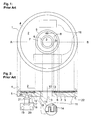
- Fig. 1 shows the recto side of a compact disc (or for short CD).
- the reference numbers denote 1 a CD, 2 information area of the CD 1, 3 a center hole in the disc, 4 an outer annulus, 5 and 6 spacing rings, 7 an identification annulus and 8 information (logos, batch numbers, letters etc.).
- the compact discs 1 are manufactured by injection moulding using an injection die (not shown here).
- the injection die is composed of two moulds enclosing the space of the CD 1.
- Their inner surfaces defining the concentric surfaces of the CD 1 are circular and parallel plane surfaces spaced about 1.2 mm apart.
- the top circular surface of the die is the master with the negative data structures for the information area 2 and for the identification annulus 7 arranged between the spacing rings 5, 6.
- the circular top surface of the die in the region of the outer annulus 4 and of the spacing rings 5, 6, and the opposite surface of the die are mirrored surfaces.
- the molten plastic usually a polycarbonate, is injected in between the moulds to become, after cooling, the body of the CD 1.
- optical discs having a larger or a smaller diameter as well as noncircular forms as well as to differing storage densities and/or means, as is the case for the Digital Video Disk (“DVD”), and to optical discs, where the data in the information area 2 may be written once or repeatedly.
- DVD Digital Video Disk
- a cut along the line A--B reveals the inner structure of the CD 1 as shown in Fig. 2.
- the CD 1 has a 1.2 mm thick disc body 9 of a clear plastic with a center hole 3 of 15 mm diameter and is concentric about an axis 10 perpendicular to the plane of the CD 1.
- the minute spacing ring 5 separates the identification annulus 7 from the information area 2.
- the larger inner spacing ring 6 is used as a clamping area.
- a CD reader (not shown here) clamps the CD 1 onto the inner spacing ring 6 to spin the CD 1 around the axis 10.
- the boundaries between the outer annulus 4, the information area 2, the spacing rings 5, 6, the identification annulus 7, and the center hole 3 are concentric, i.e. their centers coincide on the axis 10.
- the inner spacing ring 6 extends to a diameter of 33 mm and carries no data.
- the information area 2 extends from the diameters 50 mm to 116 mm and is used to store digital information of any kind (music, pictures, videos, data etc.).
- the disc body 9 On its top surface 11, the disc body 9 is structured in the information area 2 with microscopic data structures 12, and, if any, diffractive structures 13 of the information 8 (Fig. 1) within the identification annulus 7.
- the information 8 may also be printed.
- the top surface 11 is covered at least over the information area 2 with a reflective layer 14 being a few 100 nm thick and shown in the enlarged section of the data structure 12.
- the reflective layer 14 is usually a metal such as aluminum, gold, silver, etc.
- the top surface 11 and the reflective layer 14 are coated with a liquid lacquer to obtain a lacquer layer 15 of about 0.2 mm thickness.
- the fragile reflective layer 14 is completely enclosed between the disc body 9 and the lacquer layer 15.
- the lacquer layer 15 is printed or laminated with an information label 16 (Fig. 1).
- the data of the CD 1 is read out through the transparent disc body 9 by a monochromatic light beam 17 emitted by a radially moving reader head 18 comprising at least a laser light source 19 and a photo diode 20 receiving reflected light from the data structure 12.
- a lens 21 of short focal length e.g. about 2 mm, focuses the light beam 17 through the disc body 9 onto the reflective layer 14.
- the light beam 17 has about a diameter of 0.5 mm to 1 mm at the opposite surface 22 of the disc body 9 and is formed to a focal spot 23 of 1 ⁇ m diameter at the reflective layer 14 near the top surface 11. Therefore fine scratches on the opposite surface 22 do not influence the reading of the data in the information area 2.
- the CD 1 of prior art may be easily copied and unauthorized copies of the CD 1 sold.
- Several methods of copying are known, e.g.:
- the copies of the disc body 9 are reproduced by injection moulding and finished for sale to look alike to the original CD 1.
- the copy process ad c) reproduces faithfully all the diffractive gratings and hologram structures of a security device added to the top surface 3 outside the information area 2.
- the CD 1 of prior art needs therefore an integrated authentication device to distinguish the genuine CD 1 from an unauthorized one.
- the improved CD 1 has within its layers a second structured surface parallel to the top and opposite surfaces 11, 22.
- the second structured surface which also may be the opposite surface 22 itself acts as a diffractive security device, that is to be read out from the same side of the CD 1, the verso side, as the data structure 12.
- the second structured surface is defined by a step of the refractive index or by a reflective layer within the material of the CD 1.
- Fig. 3 the verso side of the improved CD 1 is shown.
- the transparent disc body 9 Fig. 2
- the reflective layer 14 Fig. 2 covering the information area 2 and, optionally, the identification annulus 7 are easily recognized (shaded areas in the drawing of Fig. 3).
- the data structure 12 Fig. 2) in the information area 2 diffracts light so that the information area 2 in white light appears as a bright annulus showing a multitude of rainbow colors.
- the information 8 (Fig. 1) of the identification annulus 7 is displayed on this side, too.
- a diffractive security label 37 may be placed instead or together with the features 24 in the area of the inner spacing ring 6 and identification annulus 7.
- the improved CD 1 uses the opposite surface 22 as an ideal area to add the additional security features 24, 37 based on diffractive gratings.
- the negative relief structure of the security features 24, 37 may be engraved into the opposite surface of the die and may extend over the whole opposite surface of the die or cover only part of the opposite surface, e.g. in the area of the identification annulus 7, the information area 2, etc.
- the disc body 9 of the moulded CD 1 carries on the opposite surface 22 the diffractive features 24 and/or the security label 37 which have been formed by the die. If the security features 24, 37 cover only part of the opposite surface 22 they can be placed anywhere on the opposite surface 22. Certain areas on the opposite surface 22 are preferred to display the security features 24, 37, e.g. the area of the inner spacing ring 6 and/or the identification annulus 7.
- the diffractive features 24, 37 are in form of a transparent rectangular mark. One mark extends over parts of the information area 2 and the outer annulus 4, whereas the other mark is placed across parts of the identification annulus 2, the spacing rings 5, 6 and the identification annulus 7.
- the security label 37 is placed in the preferred area 6, 7.
- FIG. 1 a basic embodiment of the improved CD 1 is shown in a cut along the line A-B in Fig. 4.
- Relief structures 25, 26 of the security features 24 (Fig. 3), 37 (Fig. 3) are molded into the opposite surface 22 of the disc body 9.
- the relief structures 25, 26 have a plastic/air interface through which the light beam 17 (Fig. 2) impinges upon the CD 1 while reading-out the data from the information area 2.
- the relief structures 25, 26 are not protected and allow visual inspection and authentication of unused CDs 1.
- An alternative execution of the example A has an improved visibility of the security feature 24, 37 by coating the disc body 9 on the opposite surface 22 with the relief structures 25, 26 with a transparent dielectric reflector 27 at the interface of the plastic material of the disc body 9 and air 28 as shown in the enlarged section of Fig.
- the identification annulus 7 and/or the inner ring 6 are a preferred area 6, 7 for those diffractive features 24 which are intended for visual inspection.
- another embodiment of the security label 37 uses a metallic reflector 27 instead of a dielectric one to enhance the visibility even more.
- a clear plastic fill layer 29 can be applied as a lacquer to protect the relief structures 25, 26.
- the lacquering may be realized using ink jet techniques.
- the improved CD 1 with the incorporated machine-readable diffractive feature 24 which cannot be recognized visually is executed by various methods:
- a second embodiment of the CD 1 is shown in Fig. 5.
- the disc body 9 is injection moulded using a first plastic material.
- the relief structures 25, 26 of the diffractive feature 24 (Fig. 3) are formed into the opposite surface 22.
- the relief structure 26 covers the opposite surface 22 in an area which is opposite to the information area 2.
- the relief structures 25, 26 are then advantageously completely filled in with a liquid lacquer when the whole opposite surface 22 gets completely covered, e.g. by a printing process, to obtain the clear transparent plastic fill layer 29 which protects the relief structures 25, 26.
- the plastic fill layer 29 has a smooth surface towards the air 28 as shown in the enlarged section.
- the lacquering may be realized using ink - jet techniques.
- a third embodiment of the CD 1 is the result of a two - step moulding process.
- the disc body 9 of an injection moulded data disc 30 is shown between moulds 31, 32 of the die after the first step of this process.
- the data disc 30 is thinner than the normal CD 1 (Fig. 2) of prior art.
- the top side of the data disc 30 carries the data structure 12 of the information area 2 (Fig. 2) and optionally the diffractive structure 13 (Fig. 2) of the identification annulus 7 (Fig. 2).
- the diffractive relief structures 25, 26 (Fig. 5) are on the opposite side of the data disc 30.
- the first mould 32 forming the opposite side of the data disc 30 with the negative of the relief structures 25, 26 is replaced in Fig.
- a second mould 33 where its plane 34 directed towards the opposite side of the data disc 30 is mirror - flat.
- the die is formed by the top mould 31 and the first mould 32.
- the plastic fill layer 29 is realized by a second injection moulding step adding a second plastic material to the opposite side of the data disc 30 to obtain the CD 1 with the standard thickness of 1.2 mm (+0.3 mm, -0.1 mm).
- the space between the second mould 33 and the data disc 30 is filled with the second plastic material, which forms the plastic fill layer 29.
- the fine data structure 12 and the relief structures 25, 26 are just indicated in the drawing of Figs. 6 and 7 by tinted areas, only.
- the cross section of the resulting CD 1 according to example C is shown in Fig. 8.
- the data disc 30 and the plastic fill layer 29 become a two-layered structure or laminate 35.
- the finished laminate 35 with the thickness of 1.2 mm (+0.3 mm, -0.1 mm), conforms to the CD 1 (Fig. 2) of prior art.
- the laminate 35 encloses, between the data disc 30 and the plastic fill layer 29, the diffractive relief structures 25, 26 (Fig. 5) in one or more planes at a distance from 0.5 to 1.0 mm from the reflective layer 14 (Fig.2) in the information area 2.
- the CD 1 embodiments of the examples A, B, and C receive finally the protective lacquer layer 15 (Fig. 2) and the information labels 16 (Fig. 1) on their recto side.
- the interface of two transparent materials with different refractive indices has a reflective efficiency depending on the difference D n of their refractive indices. If a relief of a diffractive structure structures the plane of the interface, the diffraction effects in reflection are visually spotted with ease if the value of the refractive index difference D n at the interface is above 0.2 albeit the materials are transparent.
- the first plastic material of the disc body 9 of example B (Fig. 5) and of example C (Fig. 6) is almost identical to the polymer material of the plastic fill layer 29. This ensures a good mechanical bond between the disc body 9 and the plastic fill layer 29.
- the materials thereof differ in their respective refractive indices. Since no metallic or dielectric reflective layer 14 (Fig. 2) separates the materials of the disc body 9 and the plastic fill layer 29, the plastic fill layer 29 cannot be dissolved without damaging the relief structures 25, 26 (Fig. 5) at the interface between the disc body 9 and the plastic fill layer 29. Therefore the diffractive feature 24 (Fig. 3) is optimally protected against forgery attempts.
- the diffractive efficiency of the diffractive feature 24 is so low that it is visually recognizable only with difficulty, if at all, because of the diffractive effects caused by the data structure 12 (Fig. 2).
- optical reading devices according to US-A 4 501 439 or US-A 5 886 798, already mentioned, are able to read out the information represented by the diffractive feature 24.
- An optimal chemical and mechanical match of the materials for the disc body 9 and the plastic fill layer 29 is obtained by using the same polymer one of which is modified to change its refractive index.
- a suitable dye By adding a suitable dye, the refractive index is changed predominantly in a spectral region ⁇ where the optical reading device is working.
- a narrow band-width dye is added to the first or second plastic material, e.g. polycarbonate, or different dyes for both plastic materials for the disc body 9 and for the plastic fill layer 29, respectively, so that the refractive index difference D n at the interface between the first and second plastic materials is 0.1 ⁇
- the diffractive feature 24 remains machine-readable but is too faint to be visible.
- Table 1 Index of refraction n D for different polymer resins Polymer Resin Index of Refraction n D Polyvinylchloride 1.60 - 1.63 Bisphenol A Polycarbonate 1.584 Polyethylene 1.50 - 1.54 Methylmetacrilate 1.49 Vinyl acetate resin 1.45 - 1.47
- the reflectance and birefringence must remain particularly within the specifications following the possible incorporation of the diffractive features 24.
- the opposite surface 22 is interesting for the addition of the diffractive features 24 while the laser beam is relatively large at this plane and relatively unaffected by the surface relief of the plastic-air interface.
- the reflectance of the transparent substrate under normal incidence and parallel beam in an unrecorded part of the information area shall be at least 70% and the relative variation of this reflectance for frequencies below 100 Hz shall be less than 3% for a disk rotating at scanning velocity which may be as low as 200 rpm. More stringent, however, is the requirement of less than 30% loss of the incident beam; this limits the visibility, for example.
- a fourth embodiment of the CD 1 is shown in Fig. 9.
- the machine-readable diffractive feature 24 as security device in the form of a overlay foil 36 or in the form of the security label 37 bonded to the smooth opposite surface 22 of the CD 1 of prior art.
- the overlay foil 36 may cover the whole opposite surface 22 albeit the security features 24, 37 are much smaller, e.g. arranged in a plurality of spots. This technique allows a straightforward application in the existing mass manufacturing processes.
- the overlay foil 36 comprises at least two thin transparent layers 38, 39 of plastic material laminated together.
- the basis layer 39 is covered on the outside of the overlay foil 36 with a heat or pressure activated glue layer 40 or the material of the basis layer 39 is the heat - or pressure - activated glue.
- the relief structures 25, 26 of the security features 24, 37 are enclosed between the front layer 38 and the basis layer 39.
- Construction examples of the overlay foil 36 are shown in US-A 4 501 439, US-A 5 104 471 or US-A 5 886 798, already mentioned.
- the overlay foil 36 is manufactured separately, stored on rolls of semitransparent labels complete with the heat or pressure activated glues ready to be bonded to any surface.
- the overlay foils 36 with different designs of the security features 24, 37 are commercially available products under the trademark TrustsealTM (TrustsealTM is a trademark owned by OVD Kinegram AG). Since CD readers have a rotation speed of the CD 1 as low as 200 rpm, the diffractive features 24 must be designed that the "average" effect on the incident light beam 17 (Fig. 2) remains under 3%. Currently known designs of the diffractive features 24 of the products TrustsealTM are particularly well suited for this purpose since the designs are fairly homogenous on millimeter scales.
- the overlay foil 36 covers at least partially the whole opposite surface 22 especially in the region of the information area 2.
- the overlay foil 36 must meet the same stringent conditions with respect to the reflection and transparency as the laminate 35 (Fig. 8) of example B.
- the diffractive feature 24 is hardly seen visually by the unaided eye through the front layer 38, if looked upon the verso side of the CD 1 in daylight.
- the data structure 12 gives such a strong background signal in rainbow colors that the diffraction effects of the diffractive feature 24 are not recognized.
- the overlay foil 36 is applied outside of the information area 2, e.g. in the preferred area 6, 7 for the security label 37.
- the security label 37 cut from the overlay foil 36 in the shape of an annulus, is arranged and bonded to the opposite surface 22 concentric to the axis 10 of the center hole 3.
- the small security label 37 of any shape is bonded to the opposite surface 22 in the preferred area 6, 7. Due to the relaxed optical condition in the preferred area 6, 7, even security labels 37 of excellent visibility may be used.
- the security features 24, 37 for the above mentioned embodiments of the CD 1 may have the relief structures 25, 26 of a well-known hologram or a mosaic of diffractive gratings.
- Advantageous are the variants mentioned below:
- the diffractive security device is the diffractive feature 24 with a Hidden Information Feature, either in combination with a visual security device or alone.
- the Hidden Information Feature is realized as a distorted Fourier hologram with a carrier frequency of more than 3'000 lines per mm and a shallow relief depth of less than 30 nm or as a kinoform according to US-A 5 886 798, already mentioned.
- the information of such a security feature 24, 37 is only recognized if illuminated with coherent light by a simple hand held reader which, in case of detecting the distorted Fourier hologram, comprises a special "matched" hologram for removing the distortion of the Fourier hologram.
- the information is visible on a screen of the reader and is an image of a logo and/or text.
- the principle of the reader is shown in Figure 8 of US-A 5 886 798, already mentioned. Two embodiments of the reader are shown in Figs. 14 and 15.
- This Hidden Information Feature in the information area 2 provides an effective second-line security device.
- the intention of the Hidden Information Feature is to allow a fast and unambiguous authentication of the CD 1. For example, a representative of a CD - manufacturer can enter stores or shops and then test the CDs using the low-cost, hand-held reader.
- Variant 2 The security label 37 as a visible security device is located in the preferred area 6, 7 and/or the outer annulus 4 and is realized by using an electron - beam (e - beam) written chrome mask 41 in Fig. 10 of a grating pattern with resolutions in the sub-micron range; each grating line is written in the mask 41 by the e-beam.
- e - beam electron - beam
- chrome mask 41 in Fig. 10 of a grating pattern with resolutions in the sub-micron range
- each grating line is written in the mask 41 by the e-beam.
- Variant 3 Back to Fig. 9, other than stringent mechanical specifications, few other specifications are given for the preferred area 6, 7 extending from the center hole 3 to the beginning of the information area 2 at the minute spacing ring 5. Because the optical constraints in this area are relaxed with respect to the information area 2, diffractive structures with relatively high diffraction efficiencies can be used. Furthermore, these effects can be optimized for transmission. For example, a Hidden Information Feature for transmission can be built into this area which projects an image onto a screen when the CD 1 is illuminated in transmission.
- Variant 4 A Double-Layer Security Device according to US-A 6 060 143, mentioned above, is shown in Fig. 11 and is composed of the security feature 24, 37 (Fig. 9) and an optical feature 47 arranged in the preferred area 6, 7 near the center hole 3.
- the relief structure 25 of the optical feature 47 and the diffractive feature 24 with the relief structure 26 would be realized the preferred area 6, 7 on both the top surface 11 and the opposite surface 22 of the disc body 9 of the CD 1, respectively.
- These diffractive features 24, 47 are realized in perfect register with one another. It should then be possible to check for galvanic copies of the CD 1 by checking the register of the two features 24, 47.
- the relief structure 25 of the diffractive feature 24 is protected by the plastic fill layer 29.
- the relief structure 25 of the optical feature 47 is a diffracting grating, too.
- Another embodiment of variant 4 is the realization of a lenticular lens array as the relief structure 25 of the optical feature 47.
- the diffractive feature 24 is observed though the lenticular lens array.
- Further embodiments of variant 4 use the security label 37 bonded to the opposite surface 22. The use of retroreflectors, microlenses, as well as reflowed lenses in combination with an overlay foil 36 having the security feature 24, 37 has potentially interesting visual effects.
- Variant 5 In one embodiment of the improved CD 1 a juxtaposition of diffractive fields, e.g. according to EP-A 0 718 834, already mentioned, is used to encode machine-readable information into the CD 1. This information refers to the company of manufacture, year of manufacture, destination (e.g. Asia or North America), identification number etc. As shown in Fig. 3 several diffractive fields 48, 49 are arranged in the identification annulus 7 about the center hole 3 of the CD 1 and form a code.
- diffractive fields 48, 49 are arranged in the identification annulus 7 about the center hole 3 of the CD 1 and form a code.
- Different diffractive structures e.g. two different diffractive structures S1 and S2 are juxtaposed to represent information; for example, a straightforward binary bar - code encoding, where small fields represent a '0' and large fields represent a '1'.
- n fields 2 n items can be distinguished. Any number m of CDs 1 can be represented by an appropriate juxtaposition of n fields.
- a cross section of an embodiment of a CD-reader unit 50 is shown featuring an additional stationary optical reader for reading-out a diffractive code with the fields 48 (Fig. 3), 49 (Fig. 3) located in the identification area 7 and/or in the outer annulus 4 of the improved CD 1.
- the optical reader comprises at least a light source 51, a detector array 52 and a signal decoder 53.
- the body 9 of the CD 1 intersects light rays 54 of the light source 51 so that the detector array 52 on the other side of the CD 1 monitors the diffracted light to distinguish the various fields 48, 49.
- the optical reader is located behind the axis 10 in order to show diffracted light 55 focussed on different detectors of the detector array 52.
- the light source 51 directs its parallel or focussed light rays 54 perpendicularly onto the CD 1 and through e.g. the identification annulus 7 where the code is located.
- the diffractive structures 25, 26 of the code diffract the light in different directions onto the detector array 52.
- the variation in time of the diffracted light 55 intensities is recorded by the detector array 52 and transformed into electrical signals.
- the signals are transferred by means of a line 56 to the signal decoder 53.
- the signal decoder 53 restitutes the code which in turn is send to an information decoder 57 by a line 58.
- the information decoder 57 starts the read-out of the information area 2 by the reader head 18 as soon as the code is stored in a memory 59 of the information decoder 57.
- the reader head 18 focusses its light beam 17 by means of the lens 21 onto the data structure 12 (Fig. 2).
- the information stored in the information area 2 is scrambled so that without the correct code the information cannot be recognized.
- the reader head 18 sends read-out scrambled data on a data line 60 to the information decoder 57 where the incoming scrambled data are decoded with a key represented by the code.
- the decoded data are transferred to an outlet 61.
- a motor 62 starts to turn the CD 1 about the axis 10.
- the detector array 52 measures the diffraction intensities as a function of time; from the time variation of the measured signals, the signal decoder 53 decodes the encrypted data of the code represented by the fields 48, 49.
- the code is designed to be read-out in transmission, in another embodiment the diffractive structures 25, 26 of the code are reflecting to be observed on the same side of the CD 1 where the light rays 54 impinges onto the opposite surface 22 of the CD 1.
- the reader head 18 is used to illuminate the code shown as the relief structure 25 at the interface between the disc body 9 and the plastic fill layer 29 in the identification area 7.
- a special optic 63 e.g. a holographic optical element, arranged on a support 64 incorporated into the light beam 17 of the currently known models of the reader heads 18 changes the focussing power of the lens 21 so that the detector array 52 is able to recognize the code.
- the reader head 18 is moved on a rail 65 in radial direction towards the axis 10 below the special optic 63 and the identification annulus 7.
- the CD 1 rotates about the axis 10 driven by the motor 62.
- the reading head 18 After recognizing and storing the code in the memory 59 the reading head 18 is moved in radial direction from under the special optic 63 in a data reading position as shown in Fig. 12 so that the light beam 17 is focussed onto the data structure 12 (Fig. 2) of the information area 2 in order to start the read-out of the data.
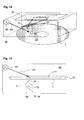
- Fig. 14 an embodiment of the hand-held reader 68 is shown with a viewing screen 69 on its top surface and its transparent bottom facing the improved CD 1.
- the light source 45 a laser
- the diffractive feature 24 of variant 1 is arranged on the illuminated surface, e.g. the opposite surface 22, of the disc body 9 (Fig. 11) and reconstructs the hidden information in reflection on the screen 69.
- the reflected light 70 forms the word "GENUINE" as the hidden information on the viewing screen 69.
- the Hidden Information Feature cannot be recognized without the coherent light rays 44 or without the viewing screen 69.
- the deflected light 73 reconstructs the visually recognizable image onto the viewing screen 69 for an observer 74 outside the housing of the reader 68.
- the holographic element 71 between the improved CD 1 and the viewing screen 69 removes the distortion.
Landscapes
- Engineering & Computer Science (AREA)
- Computer Security & Cryptography (AREA)
- Signal Processing (AREA)
- Optical Recording Or Reproduction (AREA)
- Holo Graphy (AREA)
- Optical Record Carriers And Manufacture Thereof (AREA)
- Laser Surgery Devices (AREA)
- Prostheses (AREA)
- Glass Compositions (AREA)
- Analysing Materials By The Use Of Radiation (AREA)
- Packaging For Recording Disks (AREA)
- Optical Filters (AREA)
- Electrochromic Elements, Electrophoresis, Or Variable Reflection Or Absorption Elements (AREA)
Applications Claiming Priority (2)
| Application Number | Priority Date | Filing Date | Title |
|---|---|---|---|
| US9612098P | 1998-08-10 | 1998-08-10 | |
| EP99113950A EP0980070B1 (en) | 1998-08-10 | 1999-07-17 | Diffractive security device on compact discs |
Related Parent Applications (1)
| Application Number | Title | Priority Date | Filing Date |
|---|---|---|---|
| EP99113950A Division EP0980070B1 (en) | 1998-08-10 | 1999-07-17 | Diffractive security device on compact discs |
Publications (1)
| Publication Number | Publication Date |
|---|---|
| EP1626407A2 true EP1626407A2 (en) | 2006-02-15 |
Family
ID=22255497
Family Applications (2)
| Application Number | Title | Priority Date | Filing Date |
|---|---|---|---|
| EP05023487A Withdrawn EP1626407A2 (en) | 1998-08-10 | 1999-07-17 | Diffractive security device on compact discs |
| EP99113950A Expired - Lifetime EP0980070B1 (en) | 1998-08-10 | 1999-07-17 | Diffractive security device on compact discs |
Family Applications After (1)
| Application Number | Title | Priority Date | Filing Date |
|---|---|---|---|
| EP99113950A Expired - Lifetime EP0980070B1 (en) | 1998-08-10 | 1999-07-17 | Diffractive security device on compact discs |
Country Status (8)
| Country | Link |
|---|---|
| US (1) | US6226109B1 (da) |
| EP (2) | EP1626407A2 (da) |
| AT (1) | ATE329352T1 (da) |
| DE (1) | DE69931704T2 (da) |
| DK (1) | DK0980070T3 (da) |
| ES (1) | ES2267211T3 (da) |
| PT (1) | PT980070E (da) |
| SI (1) | SI0980070T1 (da) |
Cited By (2)
| Publication number | Priority date | Publication date | Assignee | Title |
|---|---|---|---|---|
| EP1918913A1 (en) * | 2006-10-31 | 2008-05-07 | Thomson Holding Germany GmbH & Co. OHG | Method for producing a security mark on an optical data carrier |
| EP1918915A3 (en) * | 2006-10-31 | 2012-10-03 | Thomson Licensing | Method for producing a security mark on an optical data carrier |
Families Citing this family (39)
| Publication number | Priority date | Publication date | Assignee | Title |
|---|---|---|---|---|
| US6924781B1 (en) * | 1998-09-11 | 2005-08-02 | Visible Tech-Knowledgy, Inc. | Smart electronic label employing electronic ink |
| JP2000276777A (ja) * | 1999-03-25 | 2000-10-06 | Victor Co Of Japan Ltd | 光記録媒体 |
| US7088650B1 (en) * | 1999-08-23 | 2006-08-08 | Worthington Mark O | Methods and apparatus for optical disc data acquisition using physical synchronization markers |
| DE10004870A1 (de) * | 2000-02-04 | 2001-08-09 | Hsm Gmbh | Optisches Speichermedium |
| JP4278820B2 (ja) * | 2000-03-31 | 2009-06-17 | パイオニア株式会社 | 光ディスク |
| JP2001283470A (ja) * | 2000-03-31 | 2001-10-12 | Pioneer Electronic Corp | 情報記録システム及び情報記録方法 |
| US6944115B2 (en) * | 2000-09-29 | 2005-09-13 | General Electric Company | Colored data storage media |
| US6356517B1 (en) * | 2000-10-27 | 2002-03-12 | Job Tien-Chiang Liu | Optical disc with a control chip |
| JP4658448B2 (ja) * | 2000-11-14 | 2011-03-23 | コーニンクレッカ フィリップス エレクトロニクス エヌ ヴィ | ウォーターマークを有する記録担体 |
| JP4345256B2 (ja) * | 2001-02-14 | 2009-10-14 | 旭硝子株式会社 | 波長選択性回折素子および光ヘッド装置 |
| IL142382A0 (en) * | 2001-04-02 | 2002-03-10 | M M I Music Media Israel Ltd | Media card |
| CA2449171C (en) * | 2001-06-06 | 2009-08-11 | Spectra Systems Corporation | Marking and authenticating articles |
| US7393623B2 (en) * | 2001-06-06 | 2008-07-01 | Spectra Systems Corporation | Incorporation of markings in optical media |
| WO2003014836A2 (en) * | 2001-08-07 | 2003-02-20 | Pacific Holographics, Inc. | System and method for encoding and decoding an image or document and document encoded thereby |
| US6475588B1 (en) | 2001-08-07 | 2002-11-05 | General Electric Company | Colored digital versatile disks |
| JP4244551B2 (ja) * | 2001-11-30 | 2009-03-25 | ソニー株式会社 | 記録再生システム |
| US6475589B1 (en) | 2001-12-17 | 2002-11-05 | General Electric Company | Colored optical discs and methods for making the same |
| US6825960B2 (en) * | 2002-01-15 | 2004-11-30 | Inphase Technologies, Inc. | System and method for bitwise readout holographic ROM |
| US6697178B2 (en) | 2002-05-30 | 2004-02-24 | E. I. Du Pont De Nemours And Company | Disk with holographic security label applied thereto and method of applying label |
| EP1553576A4 (en) * | 2002-08-09 | 2010-11-10 | Panasonic Corp | OPTICAL DATA CARRIER AND REMOTE CONTROL DEVICE |
| JP4509934B2 (ja) | 2003-05-30 | 2010-07-21 | パナソニック株式会社 | 光ディスクおよびトラッキング制御を行う装置 |
| WO2004112096A2 (en) * | 2003-06-12 | 2004-12-23 | Symbol Technologies, Inc. | Method and system for high volume transfer of dies to substrates |
| US20070220537A1 (en) * | 2003-06-16 | 2007-09-20 | Microsoft Corporation | Counterfeit-resistant portable storage media with embedded security device |
| US7086073B2 (en) * | 2003-06-16 | 2006-08-01 | Microsoft Corporation | Optical storage media with embedded security device |
| US20040174806A1 (en) * | 2004-04-19 | 2004-09-09 | Johnson Kent Christian | Optical disc having lenticular surface and method of manufacturing |
| WO2006013528A1 (en) * | 2004-07-29 | 2006-02-09 | Koninklijke Philips Electronics N.V. | Information carrier with copy protection, system for reading such an information carrier |
| US7733754B2 (en) * | 2004-09-07 | 2010-06-08 | Dell Products L.P. | System and method for disc labeling |
| US8144558B1 (en) * | 2004-09-14 | 2012-03-27 | Doug Carson & Associates, Inc. | Hidden patterns on a data storage medium |
| US7746746B2 (en) * | 2004-11-16 | 2010-06-29 | Hewlett-Packard Development Company, L.P. | Optical media with control data in wobble |
| KR20070086659A (ko) * | 2004-11-29 | 2007-08-27 | 코닌클리케 필립스 일렉트로닉스 엔.브이. | 광 정보매체 |
| WO2006105162A2 (en) * | 2005-03-29 | 2006-10-05 | Symbol Technologies, Inc. | Smart radio frequency identification (rfid) items |
| US7830573B2 (en) * | 2005-11-03 | 2010-11-09 | Stamper Technologies, Inc. | Method and system for producing multiple images in a single image plane using diffraction |
| JP2007133948A (ja) * | 2005-11-09 | 2007-05-31 | Matsushita Electric Ind Co Ltd | 光ディスク媒体 |
| US20080063900A1 (en) * | 2006-09-11 | 2008-03-13 | Hewlett-Packard Development Company Lp | Optical storage medium |
| JP4333760B2 (ja) * | 2007-03-23 | 2009-09-16 | セイコーエプソン株式会社 | ホログラム素子、照明装置及びプロジェクタ |
| JP2008299912A (ja) * | 2007-05-29 | 2008-12-11 | Hitachi Global Storage Technologies Netherlands Bv | アライメント用パターンを備えたハードディスクメディアおよびアライメント方法 |
| WO2009088386A2 (en) * | 2008-01-08 | 2009-07-16 | Thomson Licensing | Optical system |
| CN102414729A (zh) * | 2009-04-28 | 2012-04-11 | 惠普开发有限公司 | 隐蔽标签结构 |
| WO2016073571A2 (en) * | 2014-11-05 | 2016-05-12 | Sikorsky Aircraft Corporation | Anti-counterfeiting protection and product authentication |
Family Cites Families (11)
| Publication number | Priority date | Publication date | Assignee | Title |
|---|---|---|---|---|
| CA1090631A (en) * | 1975-12-22 | 1980-12-02 | Roland Moraw | Holographic identification elements and method and apparatus for manufacture thereof |
| JPH0738270B2 (ja) * | 1989-02-21 | 1995-04-26 | パイオニア株式会社 | ディスク演奏方法 |
| DE69227175T2 (de) * | 1991-12-20 | 1999-04-29 | Eastman Kodak Co., Rochester, N.Y. | Aufzeichnungsträger für ein optisches Informationssystem mit eingebettetem Identifikationskode |
| JP2942837B2 (ja) * | 1992-01-31 | 1999-08-30 | 株式会社セガ・エンタープライゼス | セキュリティチェック方法及びゲーム装置並びにそれらに用いられる情報記憶媒体 |
| JPH05289612A (ja) * | 1992-04-06 | 1993-11-05 | Nhk Spring Co Ltd | 情報記録システム及び情報通信システム |
| FR2725069B1 (fr) * | 1994-09-28 | 1997-01-03 | Digipress Sa | Disque compact comportant un marquage anti-piratage, moule de pressage et procede de marquage anti-piratage de disques compacts |
| JPH08194972A (ja) * | 1995-01-12 | 1996-07-30 | Pioneer Video Corp | 光ディスク及びその製造装置 |
| JPH0917119A (ja) * | 1995-06-30 | 1997-01-17 | Sony Corp | データ記録媒体、データ記録方法及びデータ再生方法 |
| US5729533A (en) * | 1995-09-12 | 1998-03-17 | Wae Manufacturing Inc. | Two-sided, light-readable information recording disc stacks and methods of making same |
| GB9605729D0 (en) * | 1996-03-19 | 1996-05-22 | Applied Holographics | Optical data storage disc |
| NL1002977C2 (nl) * | 1996-05-01 | 1997-11-06 | Gpt Axxicon Bv | Werkwijze voor het vervaardigen van een optische informatiedrager alsmede optische informatiedrager. |
-
1999
- 1999-07-17 EP EP05023487A patent/EP1626407A2/en not_active Withdrawn
- 1999-07-17 ES ES99113950T patent/ES2267211T3/es not_active Expired - Lifetime
- 1999-07-17 PT PT99113950T patent/PT980070E/pt unknown
- 1999-07-17 DK DK99113950T patent/DK0980070T3/da active
- 1999-07-17 SI SI9930923T patent/SI0980070T1/sl unknown
- 1999-07-17 AT AT99113950T patent/ATE329352T1/de not_active IP Right Cessation
- 1999-07-17 EP EP99113950A patent/EP0980070B1/en not_active Expired - Lifetime
- 1999-07-17 DE DE69931704T patent/DE69931704T2/de not_active Expired - Fee Related
- 1999-08-09 US US09/370,862 patent/US6226109B1/en not_active Expired - Fee Related
Cited By (4)
| Publication number | Priority date | Publication date | Assignee | Title |
|---|---|---|---|---|
| US8953235B2 (en) | 2006-10-30 | 2015-02-10 | Thomson Licensing | Method for producing a security mark on an optical data carrier |
| EP1918913A1 (en) * | 2006-10-31 | 2008-05-07 | Thomson Holding Germany GmbH & Co. OHG | Method for producing a security mark on an optical data carrier |
| CN101183548B (zh) * | 2006-10-31 | 2012-01-04 | 汤姆森特许公司 | 在光学数据载体上形成安全标记的方法 |
| EP1918915A3 (en) * | 2006-10-31 | 2012-10-03 | Thomson Licensing | Method for producing a security mark on an optical data carrier |
Also Published As
| Publication number | Publication date |
|---|---|
| SI0980070T1 (sl) | 2006-12-31 |
| EP0980070A3 (en) | 2000-10-18 |
| ATE329352T1 (de) | 2006-06-15 |
| EP0980070B1 (en) | 2006-06-07 |
| DE69931704T2 (de) | 2007-05-10 |
| US6226109B1 (en) | 2001-05-01 |
| PT980070E (pt) | 2006-10-31 |
| DK0980070T3 (da) | 2006-10-09 |
| DE69931704D1 (de) | 2006-07-20 |
| EP0980070A2 (en) | 2000-02-16 |
| ES2267211T3 (es) | 2007-03-01 |
Similar Documents
| Publication | Publication Date | Title |
|---|---|---|
| EP0980070B1 (en) | Diffractive security device on compact discs | |
| KR0181707B1 (ko) | 광기록 매체 | |
| EP1182055B1 (en) | Optical information carrier | |
| US6060143A (en) | Optical information carrier | |
| EP1475242B1 (en) | Authentication method and system | |
| EP0968498B1 (en) | Customized graphics for dual layer optical discs | |
| EP1477940B1 (en) | Authentication method and system | |
| US5809003A (en) | Optical disk and optical information reproducing apparatus | |
| JPH0256750A (ja) | 読取り専用光デイスクへのパターン付与方法 | |
| JPH10207328A (ja) | ホログラム・カードおよびカード読み取り装置 | |
| EP1668638A1 (en) | An optical data carrier | |
| US20040066546A1 (en) | Double hologram | |
| US20080107995A1 (en) | Optical disc having lenticular surface and method of manufacturing | |
| KR100446106B1 (ko) | 바코드가 결합된 홀로그램 라벨 및 그 제조방법. | |
| US7269123B2 (en) | Wavelength selective coatings for optical disc security | |
| HK1025655A (en) | Diffractive security device on compact discs | |
| JPH09305396A (ja) | ソフトウェア記録媒体、情報読み取り装置、複製物使用防止システム、及び複製物使用防止方法 | |
| US20080049278A1 (en) | Optical information recording medium and hologram forming method for optical information recording medium | |
| JP2001100623A (ja) | 光記録媒体及び商品の真贋判定方法 | |
| US20050233141A1 (en) | Optical disc having lenticular surface and method of manufacturing | |
| JP2001184544A (ja) | 商品管理方法 | |
| JP5364085B2 (ja) | 光ディスク、その製造方法及び再生装置 | |
| EP1918913A1 (en) | Method for producing a security mark on an optical data carrier | |
| JP2583772B2 (ja) | ホログラムカード | |
| JPH07261011A (ja) | 回折構造記録体及びその読み取り方法 |
Legal Events
| Date | Code | Title | Description |
|---|---|---|---|
| PUAI | Public reference made under article 153(3) epc to a published international application that has entered the european phase |
Free format text: ORIGINAL CODE: 0009012 |
|
| AC | Divisional application: reference to earlier application |
Ref document number: 0980070 Country of ref document: EP Kind code of ref document: P |
|
| AK | Designated contracting states |
Kind code of ref document: A2 Designated state(s): AT BE CH CY DE DK ES FI FR GB GR IE IT LI LU MC NL PT SE |
|
| AX | Request for extension of the european patent |
Extension state: AL LT LV MK RO SI |
|
| STAA | Information on the status of an ep patent application or granted ep patent |
Free format text: STATUS: THE APPLICATION IS DEEMED TO BE WITHDRAWN |
|
| 18D | Application deemed to be withdrawn |
Effective date: 20080201 |