EP1627611A1 - Tête pour une pièce à main médicale de transmission d'un mouvement va-et-vient à un outil de traitement - Google Patents
Tête pour une pièce à main médicale de transmission d'un mouvement va-et-vient à un outil de traitement Download PDFInfo
- Publication number
- EP1627611A1 EP1627611A1 EP05017799A EP05017799A EP1627611A1 EP 1627611 A1 EP1627611 A1 EP 1627611A1 EP 05017799 A EP05017799 A EP 05017799A EP 05017799 A EP05017799 A EP 05017799A EP 1627611 A1 EP1627611 A1 EP 1627611A1
- Authority
- EP
- European Patent Office
- Prior art keywords
- handpiece head
- handpiece
- head
- clamping
- clamping part
- Prior art date
- Legal status (The legal status is an assumption and is not a legal conclusion. Google has not performed a legal analysis and makes no representation as to the accuracy of the status listed.)
- Granted
Links
Images
Classifications
-
- A—HUMAN NECESSITIES
- A61—MEDICAL OR VETERINARY SCIENCE; HYGIENE
- A61C—DENTISTRY; APPARATUS OR METHODS FOR ORAL OR DENTAL HYGIENE
- A61C1/00—Dental machines for boring or cutting ; General features of dental machines or apparatus, e.g. hand-piece design
- A61C1/02—Dental machines for boring or cutting ; General features of dental machines or apparatus, e.g. hand-piece design characterised by the drive of the dental tools
- A61C1/07—Dental machines for boring or cutting ; General features of dental machines or apparatus, e.g. hand-piece design characterised by the drive of the dental tools with vibratory drive, e.g. ultrasonic waves
Definitions
- the present invention relates to a handpiece head of a medical handpiece, which transmits a reciprocating movement (lifting movement) to a tool arranged in the handpiece head.
- the file should be freely rotatable relative to the handpiece, so that they always abuts the surface to be machined.
- the file in the case of molding work, it is necessary for the file to be fixed relative to the handpiece, so that, if necessary, a torque can also be exerted on the file and the workpiece.
- the file should be able to be fixed in several, different rotational positions.
- a user wants to use both modes, he currently requires two handpieces or two replaceable handpiece heads, with one handpiece (head) allowing the use of one mode.
- the application is cumbersome because during the treatment, the handpieces must be replaced and coupled to the drives or uncoupled from it. Care and cleaning measures of the handpieces or the handpiece heads must also be performed twice.
- EP 577 981 A2 discloses a handpiece head for files that allows the user to use both modes. The selection is made via an adjusting device at the upper end of the head, which is connected via a sliding coupling with the positioning coupling for adjusting the rotational position of the file.
- the positioning coupling consists of two rings with teeth that mesh with each other. One of the two rings is preloaded with a spring.
- a disadvantage of this handpiece head is that the adjustment of the rotational position of the file in stages, corresponding to the teeth of the two rings, takes place, so that the user is restricted to a limited number of rotational positions. Furthermore, a change from one mode to the other during the treatment is not possible because this moved the adjustment in the axial direction (relative to the longitudinal axis of the file) must become. For this purpose, the user needs - next to the hand holding the file - a second hand, so that the treatment is interrupted and the handpiece head with the file must be removed from the mouth. Finally, the construction and assembly costs of the handpiece head described in EP '981 with its two couplings is very high.
- the present invention is therefore based on the object by means of a structurally simple solution handpiece head for transmitting a lifting movement on a tool in such a way that the file is both freely rotatable and fixable in any position.
- the change between these two modes should preferably be carried out with one hand, so that the treatment does not have to be interrupted by removing the handpiece head from the oral cavity.
- the positioning device of the handpiece head comprises a clamp connection which is free from predetermined latching positions, thereby allowing the user to hold the tool holder, which is in operative connection with the positioning device, and a tool placed therein in any position, i.e. stepless, to fix.
- the clamping connection consists of two mutually complementary clamping parts, more preferably of clamping surfaces, which are formed as inclined planes.
- a first clamping member is rotatably connected to the rotatable about its longitudinal axis tool holder.
- the two clamping parts are movable relative to each other and can assume at least a first and a second position. In the first position, which corresponds to the first mode, the two clamping parts do not contact each other or only so slightly that the tool holder and a tool arranged therein are freely rotatable. In the second position, which corresponds to the second mode, the two clamping parts contact each other, wherein the clamping force between the two clamping parts prevents rotation of the tool holder and a tool arranged therein.
- a clamping member is connected to a movable adjusting member, preferably a slider, whereby the user Selection of the first and second position of the two clamping parts is facilitated.
- the adjusting member is displaceable parallel to the longitudinal axis of the handpiece head, in particular with a finger of that hand, which holds the handpiece head during the treatment.
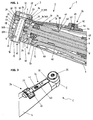
- the inventive angled handpiece head 1 shown in Figure 1 can be designed both as a replaceable head, i. via a coupling, preferably a quick coupling, be connectable to a grip sleeve of a medical handpiece, as well as a distal part of a one-piece medical handpiece.
- the handpiece head 1 consists of a neck portion 2 and a head portion 3 with respective outer sleeves 4, 5.
- the drive shaft 6 terminates distally in an eccentric pin. 7 , which is arranged eccentrically offset to the longitudinal axis 8 of the drive shaft 6.
- the drive shaft 6 is surrounded by a bearing sleeve 9, in which the rolling bearings (only one rolling bearing 10 is visible) for supporting the drive shaft 6 are located.
- a spring washer 11 biases the roller bearing 10 against the drive shaft 6 and the bearing sleeve 9. Via a shoulder 12 on the outside of the bearing sleeve 9, this is mounted on an extension 13 of the outer sleeve 5 of the head part 3.
- the tool holder 15 of the handpiece head 1 consists of a cylindrical sleeve 16 with a central bore 17 into which the tool, preferably a file, is inserted through the receiving opening 19. On the outside of the sleeve 16 two flanges 18 are arranged.
- the tool holder 15 is slidably mounted in the outer sleeve 5 of the head part 3.
- the head part 3 has a bearing bore 20 whose diameter in the section 20 A is only slightly larger than the diameter the tool holder 15.
- the tool holder 15 in the section 20 A of the bearing bore 20 has a groove 22 into which a seal 21, preferably a sealing ring is inserted, which also during operation continuously contacted the wall of the section 20 A and the interior of the handpiece head 1 seals against the environment.
- Section 20 B of the bearing bore 20 is dimensioned so that it can accommodate the flanges 18 with their larger diameters.
- the two flanges 18 form an annular groove 23 in which the eccentric pin 7 and a surrounding bearing sleeve 24, which serves as a sliding bearing, engage.
- a circular motion which is converted in a known manner by the flanges 18 and the sliding mounting of the tool holder 15 in a reciprocating motion (lifting movement) of the tool holder 15 and a tool disposed therein.
- the height of the portion 20 B of the bearing bore 20 is dimensioned so that the lifting movement of the tool holder 15 is not hindered.
- a spacer ring 27 is arranged, which is connected to a flange 28.
- Spacer ring 27 with flange 28 is rotatably connected to the sleeve 16 by two pins 29 which engage in two slots 26 of the sleeve 16.
- the pins 29 are pressed into two holes 30 of the spacer ring 27.
- the length of the two slots 26 is in turn dimensioned so that they do not hinder the lifting movement of the tool holder 15.
- Flange 28 has a first clamping part 31, i.e. a surface 31 A, which is formed as an inclined plane, whereby the flange 28 has a radially (relative to the longitudinal axis 32 of the tool holder 15) outwardly tapering, wedge-shaped.
- Flange 28, spacer ring 27 and cap 25 as a rotationally fixed component of the handpiece head 1 form a recess 33, which also has a wedge-shaped, radially inwardly tapering shape due to the oblique plane formed surface 31 A.
- a second clamping member 34 In the immediate vicinity of the first clamping member 31 is as part of an extension 35, a second clamping member 34, ie a surface 34 A, which is also formed as an inclined plane arranged.
- Clamping member 34 with surface 34 A is movable with respect to clamping member 31 with surface 31 A and can assume at least a first and a second position.
- the two clamping members 31, 34 do not contact each other or only so little that the tool holder 15 and a therein arranged tool about the axis 32 are freely rotatable.
- the wedge-shaped, tapered extension 35 does not engage in the recess 33 substantially.
- the two surfaces 31 A, 34 A contact each other and the clamping force between the two clamping parts 31, 34 prevent rotation of the spacer ring 27, the rotatably connected to the ring 27 tool holder 15 and a tool disposed therein.
- this positioning device 14 designed as a clamping connection, which is free of predetermined latching positions, the tool, preferably a file, can be fixed in any desired position.
- Extension 35 with clamping part 34 is connected to facilitate the sliding operation with an adjusting member 36, preferably in the form of a slide 37.
- Slider 37 is connected to the handpiece head 1 by means of a fixing element, preferably a screw 38, which is screwed into a bore 39 of the outer sleeve 4.
- the head 41 of the screw 38 is received in a slot 40 whose width is smaller, but whose longitudinal extent is greater than the diameter of the screw head 41, whereby the slider 37 along the longitudinal axis 8 of the handpiece head 1 is displaceable.
- an operating device 54 in the form of a projection 42, which serves the user as a preferred attack surface for the adjusting member 36.
- the user can move the adjusting member 36 with the hand holding the handpiece head 1 without having to remove the handpiece head 1 from the oral cavity and interrupt the treatment.
- a bore 43 Inside the projection 42 is a bore 43, the opening 44 of the outer sleeve 4 faces.
- a spring element 45 and a latching element, preferably a ball 46 are accommodated.
- the ball 46 is also displaced and locked due to the force exerted by the spring element 45 force in the recess 47 a. This prevents that the two clamping members 31, 34 unintentionally move away from each other during the treatment and the rotatably fixed tool holder 15 is released from its position. If the user selects the first position (free rotation of the tool holder 15), he pushes with the adjusting member 36, the locking element 46 against the force of the spring element 45 from the recess 47th
- a light guide 48 is arranged in the handpiece head 1, the distal end of which discharges the light in an opening 49.
- a spray channel 50 which opens in the vicinity of the tool holder 15, treatment liquid is discharged to the tool and the treatment site.
- Optical fiber 48 and spray channel 50 extend in a known manner through the handpiece head 1 or the handpiece and are connected to respective media sources.
- Figure 2 shows the handpiece head 1 according to the invention in a perspective view. Construction and function of the positioning device for the tool designed as a clamping connection correspond to FIG. 1.
- the operating device 54 is formed at the proximal end of the adjusting member 36 designed as a slide 37 by at least one laterally arranged vanes 51 or 52.
- the operation of the handpiece head 1 becomes even more comfortable: during the treatment, the user holds the handpiece head 1 like a ballpoint pen between his fingers, i. the middle finger serves as a support for the handpiece head 1, index finger and thumb stabilize the handpiece head 1 laterally.
- the laterally arranged wings 51, 52 which preferably have slight depressions 53 for a fingertip, optionally with a surface structure, further facilitate the user's displacement of the adjusting member 36 along the longitudinal axis 8 of the handpiece head 1 without interrupting the treatment. Since the shifting operation is preferably performed with the index finger, it is advantageous to arrange on both sides of the slider 37 a wing 51, 52, whereby the handpiece head 1 is to be used universally for right and left-handers.
- the invention is not limited to the illustrated field of application and the described embodiment, but includes all possible embodiments that do not change the basic, analogous operating principle of the invention.
Landscapes
- Health & Medical Sciences (AREA)
- Oral & Maxillofacial Surgery (AREA)
- Dentistry (AREA)
- Epidemiology (AREA)
- Life Sciences & Earth Sciences (AREA)
- Animal Behavior & Ethology (AREA)
- General Health & Medical Sciences (AREA)
- Public Health (AREA)
- Veterinary Medicine (AREA)
- Dental Tools And Instruments Or Auxiliary Dental Instruments (AREA)
- Manipulator (AREA)
Applications Claiming Priority (1)
| Application Number | Priority Date | Filing Date | Title |
|---|---|---|---|
| AT0138704A AT502358B1 (de) | 2004-08-18 | 2004-08-18 | Medizinischer handstückkopf zur übertragung einer hubbewegung auf ein werkzeug |
Publications (2)
| Publication Number | Publication Date |
|---|---|
| EP1627611A1 true EP1627611A1 (fr) | 2006-02-22 |
| EP1627611B1 EP1627611B1 (fr) | 2009-10-21 |
Family
ID=35159978
Family Applications (1)
| Application Number | Title | Priority Date | Filing Date |
|---|---|---|---|
| EP05017799A Expired - Lifetime EP1627611B1 (fr) | 2004-08-18 | 2005-08-17 | Tête pour une pièce à main médicale de transmission d'un mouvement va-et-vient à un outil de traitement |
Country Status (3)
| Country | Link |
|---|---|
| EP (1) | EP1627611B1 (fr) |
| AT (2) | AT502358B1 (fr) |
| DE (1) | DE502005008364D1 (fr) |
Cited By (4)
| Publication number | Priority date | Publication date | Assignee | Title |
|---|---|---|---|---|
| EP2754406A1 (fr) | 2013-01-14 | 2014-07-16 | W & H Dentalwerk Bürmoos GmbH | Pièce à main médicale, en particulier dentaire |
| CN103945788A (zh) * | 2011-11-21 | 2014-07-23 | W和H牙科产品比莫斯有限公司 | 用于医疗工具尤其是牙科或外科工具的驱动装置 |
| EP3298981A1 (fr) * | 2016-09-22 | 2018-03-28 | Sirona Dental Systems GmbH | Tête pour une pièce à main dentaire |
| WO2023169822A1 (fr) | 2022-03-10 | 2023-09-14 | Kavo Dental Gmbh | Tête d'instrument avec mécanisme de levier pour serrage d'un outil de traitement |
Citations (5)
| Publication number | Priority date | Publication date | Assignee | Title |
|---|---|---|---|---|
| US3578745A (en) * | 1968-05-06 | 1971-05-18 | Marcel Garnier | Dental instrument |
| US4295827A (en) * | 1979-12-31 | 1981-10-20 | Howard Martin | Endodontic flow through ultrasonic instrument holder attachment |
| EP0387980A1 (fr) * | 1989-03-13 | 1990-09-19 | Samuel Shiber | Système d'athérectomie avec un embrayage |
| US4976625A (en) * | 1988-04-08 | 1990-12-11 | Bernard Weissman | Inherently nonrotating reciprocating dental tool |
| EP0577981A2 (fr) | 1992-06-05 | 1994-01-12 | Kaltenbach & Voigt Gmbh & Co. | Tête pour une pièce à main médicale ou dentaire comportant un outil de traitement oscillant |
-
2004
- 2004-08-18 AT AT0138704A patent/AT502358B1/de not_active IP Right Cessation
-
2005
- 2005-08-17 EP EP05017799A patent/EP1627611B1/fr not_active Expired - Lifetime
- 2005-08-17 DE DE502005008364T patent/DE502005008364D1/de not_active Expired - Lifetime
- 2005-08-17 AT AT05017799T patent/ATE446058T1/de active
Patent Citations (5)
| Publication number | Priority date | Publication date | Assignee | Title |
|---|---|---|---|---|
| US3578745A (en) * | 1968-05-06 | 1971-05-18 | Marcel Garnier | Dental instrument |
| US4295827A (en) * | 1979-12-31 | 1981-10-20 | Howard Martin | Endodontic flow through ultrasonic instrument holder attachment |
| US4976625A (en) * | 1988-04-08 | 1990-12-11 | Bernard Weissman | Inherently nonrotating reciprocating dental tool |
| EP0387980A1 (fr) * | 1989-03-13 | 1990-09-19 | Samuel Shiber | Système d'athérectomie avec un embrayage |
| EP0577981A2 (fr) | 1992-06-05 | 1994-01-12 | Kaltenbach & Voigt Gmbh & Co. | Tête pour une pièce à main médicale ou dentaire comportant un outil de traitement oscillant |
Cited By (8)
| Publication number | Priority date | Publication date | Assignee | Title |
|---|---|---|---|---|
| CN103945788A (zh) * | 2011-11-21 | 2014-07-23 | W和H牙科产品比莫斯有限公司 | 用于医疗工具尤其是牙科或外科工具的驱动装置 |
| CN106974736A (zh) * | 2011-11-21 | 2017-07-25 | W和H牙科产品比莫斯有限公司 | 用于医疗工具尤其是牙科或外科工具的驱动装置 |
| CN106974736B (zh) * | 2011-11-21 | 2019-06-28 | W和H牙科产品比莫斯有限公司 | 用于医疗工具尤其是牙科或外科工具的驱动装置 |
| EP2754406A1 (fr) | 2013-01-14 | 2014-07-16 | W & H Dentalwerk Bürmoos GmbH | Pièce à main médicale, en particulier dentaire |
| US8961177B2 (en) | 2013-01-14 | 2015-02-24 | W&H Dentalwerk Bürmoos GmbH | Medical or dental handpiece |
| EP3298981A1 (fr) * | 2016-09-22 | 2018-03-28 | Sirona Dental Systems GmbH | Tête pour une pièce à main dentaire |
| WO2023169822A1 (fr) | 2022-03-10 | 2023-09-14 | Kavo Dental Gmbh | Tête d'instrument avec mécanisme de levier pour serrage d'un outil de traitement |
| DE102022105626A1 (de) | 2022-03-10 | 2023-09-14 | Kavo Dental Gmbh | Instrumentenkopf mit hebelmechanismus zum spannen eines behandlungswerkzeugs |
Also Published As
| Publication number | Publication date |
|---|---|
| AT502358B1 (de) | 2008-10-15 |
| AT502358A2 (de) | 2007-03-15 |
| AT502358A3 (de) | 2008-08-15 |
| EP1627611B1 (fr) | 2009-10-21 |
| ATE446058T1 (de) | 2009-11-15 |
| DE502005008364D1 (de) | 2009-12-03 |
Similar Documents
| Publication | Publication Date | Title |
|---|---|---|
| DE69629895T2 (de) | Schlüsselloser Spannfutter für chirurgisches Blatt | |
| DE10358554B4 (de) | Chirurgisches Instrument zum Sezieren von Knochen oder anderem Gewebe mit Teleskopaufsatz | |
| DE3711377C2 (de) | Chirurgisches Instrument | |
| EP0642770B1 (fr) | Pièce à main contre-angle ou droite avec dispositif de serrage détachable pour un outil, en particulier pour des fins médicales | |
| DE1219170B (de) | Zahnaerztliches Hand- oder Winkelstueck | |
| DE102017010033A1 (de) | Medizinische Vorrichtung | |
| WO2011076364A1 (fr) | Instrument chirurgical pour le raccordement amovible d'une pièce à main à un outil chirurgical | |
| DE2855359A1 (de) | Zahnaerztliches handstueck | |
| EP1790292B1 (fr) | Dispositif d'accouplement chirurgical | |
| EP0118515B1 (fr) | Piece coudee pour dentiste | |
| DE4103663A1 (de) | Chirurgisches handstueck | |
| EP0925762B1 (fr) | Outil pour une pièce à main contre-angle ou droite avec dispositif de serrage détachable pour l'outil, en particulier pour des fins médicales | |
| EP1627611B1 (fr) | Tête pour une pièce à main médicale de transmission d'un mouvement va-et-vient à un outil de traitement | |
| DE2650864C2 (de) | Klemmelement zum Festklemmen auf einem Instrumentenschaft | |
| EP0958791B1 (fr) | Detachable chuck for a medical or dental rotating tool | |
| DE3343867A1 (de) | Vorrichtung zur loesbaren befestigung des aufsatzes eines chirurgischen instruments | |
| EP2754406B1 (fr) | Pièce à main médicale, en particulier dentaire | |
| DE4210911A1 (de) | Schnellspanneinrichtung | |
| WO1982003760A1 (fr) | Outil a forer avec support d'outil oscillant | |
| DE2937885C2 (de) | Zahnärztliches Handstück | |
| DE2020449A1 (de) | Schluessellos bedienbares Mehrbackenspannfutter | |
| DE10132358A1 (de) | Chirurgisches Instrument | |
| EP4547129B1 (fr) | Instrument chirurgical et procédé pour le démonter | |
| EP1534150B1 (fr) | Instrument chirurgical | |
| DE163086C (fr) |
Legal Events
| Date | Code | Title | Description |
|---|---|---|---|
| PUAI | Public reference made under article 153(3) epc to a published international application that has entered the european phase |
Free format text: ORIGINAL CODE: 0009012 |
|
| AK | Designated contracting states |
Kind code of ref document: A1 Designated state(s): AT BE BG CH CY CZ DE DK EE ES FI FR GB GR HU IE IS IT LI LT LU LV MC NL PL PT RO SE SI SK TR |
|
| AX | Request for extension of the european patent |
Extension state: AL BA HR MK YU |
|
| 17P | Request for examination filed |
Effective date: 20060628 |
|
| AKX | Designation fees paid |
Designated state(s): AT BE BG CH CY CZ DE DK EE ES FI FR GB GR HU IE IS IT LI LT LU LV MC NL PL PT RO SE SI SK TR |
|
| 17Q | First examination report despatched |
Effective date: 20080311 |
|
| GRAP | Despatch of communication of intention to grant a patent |
Free format text: ORIGINAL CODE: EPIDOSNIGR1 |
|
| GRAS | Grant fee paid |
Free format text: ORIGINAL CODE: EPIDOSNIGR3 |
|
| GRAA | (expected) grant |
Free format text: ORIGINAL CODE: 0009210 |
|
| AK | Designated contracting states |
Kind code of ref document: B1 Designated state(s): AT BE BG CH CY CZ DE DK EE ES FI FR GB GR HU IE IS IT LI LT LU LV MC NL PL PT RO SE SI SK TR |
|
| REG | Reference to a national code |
Ref country code: GB Ref legal event code: FG4D Free format text: NOT ENGLISH |
|
| REG | Reference to a national code |
Ref country code: CH Ref legal event code: EP |
|
| REG | Reference to a national code |
Ref country code: IE Ref legal event code: FG4D |
|
| REF | Corresponds to: |
Ref document number: 502005008364 Country of ref document: DE Date of ref document: 20091203 Kind code of ref document: P |
|
| LTIE | Lt: invalidation of european patent or patent extension |
Effective date: 20091021 |
|
| NLV1 | Nl: lapsed or annulled due to failure to fulfill the requirements of art. 29p and 29m of the patents act | ||
| PG25 | Lapsed in a contracting state [announced via postgrant information from national office to epo] |
Ref country code: FI Free format text: LAPSE BECAUSE OF FAILURE TO SUBMIT A TRANSLATION OF THE DESCRIPTION OR TO PAY THE FEE WITHIN THE PRESCRIBED TIME-LIMIT Effective date: 20091021 Ref country code: PT Free format text: LAPSE BECAUSE OF FAILURE TO SUBMIT A TRANSLATION OF THE DESCRIPTION OR TO PAY THE FEE WITHIN THE PRESCRIBED TIME-LIMIT Effective date: 20100222 Ref country code: LT Free format text: LAPSE BECAUSE OF FAILURE TO SUBMIT A TRANSLATION OF THE DESCRIPTION OR TO PAY THE FEE WITHIN THE PRESCRIBED TIME-LIMIT Effective date: 20091021 Ref country code: SE Free format text: LAPSE BECAUSE OF FAILURE TO SUBMIT A TRANSLATION OF THE DESCRIPTION OR TO PAY THE FEE WITHIN THE PRESCRIBED TIME-LIMIT Effective date: 20091021 Ref country code: IS Free format text: LAPSE BECAUSE OF FAILURE TO SUBMIT A TRANSLATION OF THE DESCRIPTION OR TO PAY THE FEE WITHIN THE PRESCRIBED TIME-LIMIT Effective date: 20100221 Ref country code: ES Free format text: LAPSE BECAUSE OF FAILURE TO SUBMIT A TRANSLATION OF THE DESCRIPTION OR TO PAY THE FEE WITHIN THE PRESCRIBED TIME-LIMIT Effective date: 20100201 |
|
| REG | Reference to a national code |
Ref country code: IE Ref legal event code: FD4D |
|
| PG25 | Lapsed in a contracting state [announced via postgrant information from national office to epo] |
Ref country code: LV Free format text: LAPSE BECAUSE OF FAILURE TO SUBMIT A TRANSLATION OF THE DESCRIPTION OR TO PAY THE FEE WITHIN THE PRESCRIBED TIME-LIMIT Effective date: 20091021 Ref country code: SI Free format text: LAPSE BECAUSE OF FAILURE TO SUBMIT A TRANSLATION OF THE DESCRIPTION OR TO PAY THE FEE WITHIN THE PRESCRIBED TIME-LIMIT Effective date: 20091021 Ref country code: PL Free format text: LAPSE BECAUSE OF FAILURE TO SUBMIT A TRANSLATION OF THE DESCRIPTION OR TO PAY THE FEE WITHIN THE PRESCRIBED TIME-LIMIT Effective date: 20091021 |
|
| PG25 | Lapsed in a contracting state [announced via postgrant information from national office to epo] |
Ref country code: RO Free format text: LAPSE BECAUSE OF FAILURE TO SUBMIT A TRANSLATION OF THE DESCRIPTION OR TO PAY THE FEE WITHIN THE PRESCRIBED TIME-LIMIT Effective date: 20091021 Ref country code: BG Free format text: LAPSE BECAUSE OF FAILURE TO SUBMIT A TRANSLATION OF THE DESCRIPTION OR TO PAY THE FEE WITHIN THE PRESCRIBED TIME-LIMIT Effective date: 20100121 Ref country code: DK Free format text: LAPSE BECAUSE OF FAILURE TO SUBMIT A TRANSLATION OF THE DESCRIPTION OR TO PAY THE FEE WITHIN THE PRESCRIBED TIME-LIMIT Effective date: 20091021 Ref country code: EE Free format text: LAPSE BECAUSE OF FAILURE TO SUBMIT A TRANSLATION OF THE DESCRIPTION OR TO PAY THE FEE WITHIN THE PRESCRIBED TIME-LIMIT Effective date: 20091021 Ref country code: IE Free format text: LAPSE BECAUSE OF FAILURE TO SUBMIT A TRANSLATION OF THE DESCRIPTION OR TO PAY THE FEE WITHIN THE PRESCRIBED TIME-LIMIT Effective date: 20091021 |
|
| PLBE | No opposition filed within time limit |
Free format text: ORIGINAL CODE: 0009261 |
|
| STAA | Information on the status of an ep patent application or granted ep patent |
Free format text: STATUS: NO OPPOSITION FILED WITHIN TIME LIMIT |
|
| PG25 | Lapsed in a contracting state [announced via postgrant information from national office to epo] |
Ref country code: SK Free format text: LAPSE BECAUSE OF FAILURE TO SUBMIT A TRANSLATION OF THE DESCRIPTION OR TO PAY THE FEE WITHIN THE PRESCRIBED TIME-LIMIT Effective date: 20091021 Ref country code: CZ Free format text: LAPSE BECAUSE OF FAILURE TO SUBMIT A TRANSLATION OF THE DESCRIPTION OR TO PAY THE FEE WITHIN THE PRESCRIBED TIME-LIMIT Effective date: 20091021 |
|
| 26N | No opposition filed |
Effective date: 20100722 |
|
| PG25 | Lapsed in a contracting state [announced via postgrant information from national office to epo] |
Ref country code: GR Free format text: LAPSE BECAUSE OF FAILURE TO SUBMIT A TRANSLATION OF THE DESCRIPTION OR TO PAY THE FEE WITHIN THE PRESCRIBED TIME-LIMIT Effective date: 20100122 |
|
| BERE | Be: lapsed |
Owner name: W & H DENTALWERK BURMOOS GMBH Effective date: 20100831 |
|
| PG25 | Lapsed in a contracting state [announced via postgrant information from national office to epo] |
Ref country code: IT Free format text: LAPSE BECAUSE OF FAILURE TO SUBMIT A TRANSLATION OF THE DESCRIPTION OR TO PAY THE FEE WITHIN THE PRESCRIBED TIME-LIMIT Effective date: 20091021 Ref country code: MC Free format text: LAPSE BECAUSE OF NON-PAYMENT OF DUE FEES Effective date: 20100831 |
|
| PG25 | Lapsed in a contracting state [announced via postgrant information from national office to epo] |
Ref country code: BE Free format text: LAPSE BECAUSE OF NON-PAYMENT OF DUE FEES Effective date: 20100831 |
|
| PG25 | Lapsed in a contracting state [announced via postgrant information from national office to epo] |
Ref country code: CY Free format text: LAPSE BECAUSE OF FAILURE TO SUBMIT A TRANSLATION OF THE DESCRIPTION OR TO PAY THE FEE WITHIN THE PRESCRIBED TIME-LIMIT Effective date: 20091021 |
|
| PG25 | Lapsed in a contracting state [announced via postgrant information from national office to epo] |
Ref country code: LU Free format text: LAPSE BECAUSE OF NON-PAYMENT OF DUE FEES Effective date: 20100817 Ref country code: HU Free format text: LAPSE BECAUSE OF FAILURE TO SUBMIT A TRANSLATION OF THE DESCRIPTION OR TO PAY THE FEE WITHIN THE PRESCRIBED TIME-LIMIT Effective date: 20100422 Ref country code: NL Free format text: LAPSE BECAUSE OF FAILURE TO SUBMIT A TRANSLATION OF THE DESCRIPTION OR TO PAY THE FEE WITHIN THE PRESCRIBED TIME-LIMIT Effective date: 20091021 |
|
| PG25 | Lapsed in a contracting state [announced via postgrant information from national office to epo] |
Ref country code: TR Free format text: LAPSE BECAUSE OF FAILURE TO SUBMIT A TRANSLATION OF THE DESCRIPTION OR TO PAY THE FEE WITHIN THE PRESCRIBED TIME-LIMIT Effective date: 20091021 |
|
| PGFP | Annual fee paid to national office [announced via postgrant information from national office to epo] |
Ref country code: GB Payment date: 20120821 Year of fee payment: 8 |
|
| PGFP | Annual fee paid to national office [announced via postgrant information from national office to epo] |
Ref country code: AT Payment date: 20120813 Year of fee payment: 8 |
|
| REG | Reference to a national code |
Ref country code: AT Ref legal event code: MM01 Ref document number: 446058 Country of ref document: AT Kind code of ref document: T Effective date: 20130817 |
|
| GBPC | Gb: european patent ceased through non-payment of renewal fee |
Effective date: 20130817 |
|
| PG25 | Lapsed in a contracting state [announced via postgrant information from national office to epo] |
Ref country code: AT Free format text: LAPSE BECAUSE OF NON-PAYMENT OF DUE FEES Effective date: 20130817 |
|
| PG25 | Lapsed in a contracting state [announced via postgrant information from national office to epo] |
Ref country code: GB Free format text: LAPSE BECAUSE OF NON-PAYMENT OF DUE FEES Effective date: 20130817 |
|
| REG | Reference to a national code |
Ref country code: FR Ref legal event code: PLFP Year of fee payment: 11 |
|
| PGFP | Annual fee paid to national office [announced via postgrant information from national office to epo] |
Ref country code: FR Payment date: 20150626 Year of fee payment: 11 |
|
| PGFP | Annual fee paid to national office [announced via postgrant information from national office to epo] |
Ref country code: DE Payment date: 20150821 Year of fee payment: 11 Ref country code: CH Payment date: 20150819 Year of fee payment: 11 |
|
| REG | Reference to a national code |
Ref country code: DE Ref legal event code: R119 Ref document number: 502005008364 Country of ref document: DE |
|
| REG | Reference to a national code |
Ref country code: CH Ref legal event code: PL |
|
| PG25 | Lapsed in a contracting state [announced via postgrant information from national office to epo] |
Ref country code: CH Free format text: LAPSE BECAUSE OF NON-PAYMENT OF DUE FEES Effective date: 20160831 Ref country code: LI Free format text: LAPSE BECAUSE OF NON-PAYMENT OF DUE FEES Effective date: 20160831 |
|
| REG | Reference to a national code |
Ref country code: FR Ref legal event code: ST Effective date: 20170428 |
|
| PG25 | Lapsed in a contracting state [announced via postgrant information from national office to epo] |
Ref country code: FR Free format text: LAPSE BECAUSE OF NON-PAYMENT OF DUE FEES Effective date: 20160831 Ref country code: DE Free format text: LAPSE BECAUSE OF NON-PAYMENT OF DUE FEES Effective date: 20170301 |