EP1627746A2 - Druckvorrichtung mit Strahlungsquelle - Google Patents
Druckvorrichtung mit Strahlungsquelle Download PDFInfo
- Publication number
- EP1627746A2 EP1627746A2 EP05076855A EP05076855A EP1627746A2 EP 1627746 A2 EP1627746 A2 EP 1627746A2 EP 05076855 A EP05076855 A EP 05076855A EP 05076855 A EP05076855 A EP 05076855A EP 1627746 A2 EP1627746 A2 EP 1627746A2
- Authority
- EP
- European Patent Office
- Prior art keywords
- image
- carriage
- radiation source
- receiving member
- scanning direction
- Prior art date
- Legal status (The legal status is an assumption and is not a legal conclusion. Google has not performed a legal analysis and makes no representation as to the accuracy of the status listed.)
- Granted
Links
Images
Classifications
-
- B—PERFORMING OPERATIONS; TRANSPORTING
- B41—PRINTING; LINING MACHINES; TYPEWRITERS; STAMPS
- B41J—TYPEWRITERS; SELECTIVE PRINTING MECHANISMS, i.e. MECHANISMS PRINTING OTHERWISE THAN FROM A FORME; CORRECTION OF TYPOGRAPHICAL ERRORS
- B41J11/00—Devices or arrangements of selective printing mechanisms, e.g. ink-jet printers or thermal printers, for supporting or handling copy material in sheet or web form
- B41J11/0015—Devices or arrangements of selective printing mechanisms, e.g. ink-jet printers or thermal printers, for supporting or handling copy material in sheet or web form for treating before, during or after printing or for uniform coating or laminating the copy material before or after printing
- B41J11/002—Curing or drying the ink on the copy materials, e.g. by heating or irradiating
- B41J11/0021—Curing or drying the ink on the copy materials, e.g. by heating or irradiating using irradiation
- B41J11/00214—Curing or drying the ink on the copy materials, e.g. by heating or irradiating using irradiation using UV radiation
Definitions
- the present invention is related to a printing device such as a printing or copying system employing print heads containing discharging elements, e.g. nozzles, for image-wise forming dots of a marking substance on an image-receiving member, where the marking substance is in fluid form when discharged and is thereafter exposed to a radiation source.
- the marking substance may be a UV curable ink, while the radiation source is a UV radiation curing source.
- Print heads employed in inkjet printers and the like usually each contain a plurality of nozzles arranged in (an) array(s).
- the nozzles usually are placed substantially equidistant. The distance between two contiguous nozzles defines the nozzle pitch.
- the nozzles are controlled to image-wise discharge fluid droplets of a marking substance on an image-receiving member.
- the print heads are supported on a carriage which is moveable in reciprocation across the image-receiving member, i.e. the main scanning direction. In such printers, the print heads are typically aligned in the sub scanning direction perpendicular to the main scanning direction.
- a matrix of image dots of a marking substance, corresponding to a part of an original image is formed on the image-receiving member by image-wise activating selected nozzles of the print heads.
- the printed matrix is generally referred to as a print swath, while the dimension of this matrix in the sub scanning direction is referred to as the swath width.
- the printing swath is constant within a selected printing mode.
- this displacement step is chosen equal to a swath width
- an image can be printed in multiple nonoverlapping swaths.
- An advantage of such approach is the high productivity as only a single printing stage is employed.
- image quality may be improved by employing printing devices enabling the use of multiple printing stages.
- two main categories of such printing devices can be distinguished, i.e. so-called “interlace systems” and "multi-pass systems”.
- the print head contains N nozzles, which are arranged in (a) linear array(s) such that the nozzle pitch is an integer multiple of the printing pitch. Multiple printing stages, or so-called interlacing printing steps, are required to generale a complete image.
- the print head and the image-receiving member are controlled such that in M printing steps, M being defined here as the nozzle pitch divided by the printing pitch, a complete image part is formed on the image-receiving member. After each printing step, the image-receiving member is displaced over a distance of M times the printing pitch.
- the print head is controlled such that only the nozzles corresponding to selected pixels of the image to be reproduced are image-wise activated.
- an incomplete matrix of image dots is formed in a single printing stage or pass, i.e. one traverse of the print heads across the image-receiving member. Multiple passes are required to complete the matrix of image dots. In-between two passes the image-receiving member may be displaced in the sub scanning direction.
- the image dots of marking substance are subjected to irradiation by a radiation source which may be positioned laterally adjacent the carriage on the carriage itself or on a separate mount moveable in co-operation with the carriage. This may be done for several purposes including to prevent or contral bleeding, to improve adhesion, in case of a solvent based marking substance to remove the solvents, in case of a radiation curable marking substance to set or cure the marking substance.
- the radiation source(s) is (are) are mounted in such a way that all the marking substance deposited on the image-receiving member is exposed to radiation.
- the marking substance is an UV curable ink and the radiation source is a mercury vapour lamp
- the swath of ink jetted on the image-receiving member in one traverse of the carriage is typically much wider than the incremental displacement of the carriage relative to the image-receiving member.
- ink discharged from nozzles positioned on one side of the carriage in the sub scanning direction will be exposed to multiple doses of radiation while ink discharged from nozzles positioned on the opposite side of the carriage may only be exposed to a single dose of radiation originating from a single traverse of the lamp.
- the overall power output level of the lamp must be increased in order to ensure that all ink deposited, including the ink exposed to only a single traverse of the lamp, receives the minimum radiation dose required to cure the ink.
- the increase in power level also results in an increase of heat which is particularly undesired when curing ink deposited on thermal sensitive image-receiving members.
- part of the ink deposited is exposed to multiple traverses of the UV lamp, which output level is increased, and hence overcuring may occur as some inks are sensitive thereto.
- a printing device comprising:
- each radiation source is non-linear shaped.
- the non-linear UV radiation source may be a xenon lamp or may be composed of a plurality of LED's or other UV emitting devices.
- the or each radiation source is composed of a plurality of radiation units.
- Control means are provided for controlling each of the plurality of radiation units such that the radiation dose received by the image dots in an area on the image-receiving member increases towards an edge of the dimension in the sub scanning direction of the area irradiated by the radiation source in a traverse.
- the control means control the radiation units such that different radiation units generate different output power levels. This control can be done by matching the output level of the respective radiation units to a predetermined output profile.
- each of the radiation units is a LED or a LED array.
- the marking substance is a UV curable ink and the radiation sources are xenon flash lamps, it is apparent however that a person skilled in the art can imagine several other equivalent embodiments or other ways of executing the present invention.
- the marking substance may be any marking substance which can be discharged in fluid form including but not limited to a solvent or aqueous based ink, a UV curable ink, a liquid toner, a hot melt ink, while the radiation source may be a drying source including a halogen lamp or a curing source including mercury vapour lamps, xenon flash lamps, and LED's.
- the scope of the present invention is limited only by the terms of the appended claims.
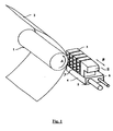
- the printing device of fig.1 is an inkjet printer suited for printing with UV curable ink.
- the printing device comprises a roller (1) for supporting an image-receiving member (2) and moving it along four print heads (3), each of a different process colour.
- the roller is rotatable about its axis as indicated by arrow A.
- a scanning carriage (4) carries the four print heads and can be moved in reciprocation in the main scanning direction, i.e. the direction indicated by the double arrow B, parallel to the roller (1), such as to enable scanning of the image-receiving member in the main scanning direction.
- the image-receiving member can be a medium in web or in sheet form and may be composed of e.g. paper, cardboard, label stock, plastic or textile.
- the image-receiving member can also be an intermediate member, endless or not.
- the carriage further supports a radiation source (8) for irradiating the ink dots.
- the carriage (4) is guided on rods (5) (6) and is driven by suitable means (not shown).
- Each print head comprises a number of discharging elements (7) arranged in a single linear array parallel to the sub scanning direction. Four discharging elements per print head are depicted in the figure. However, in a typical practical embodiment several hundred or thousand of discharging elements are provided per print head and are arranged in a single or multiple arrays. Each discharging element is connected via an ink duet to an ink reservoir of the corresponding colour.
- Each ink duet is provided with means for activating the ink duet and an associated electrical drive circuit.
- the ink duet may be activated thermally and/or piezoelectrically.
- an ink drop is discharged form the discharge element in the direction of the roller (1) and forms a dot of ink on the image-receiving member.
- a print swath is formed by image-wise activating selected discharging elements in relation to the pattern(s) of pixels of an image or document to be reproduced, while the carriage is moved across the image-receiving member.
- the radiation source (8) schematically indicated in Fig.1 irradiates at least the ink dots deposited during the print swath and has a dimension in the sub-scanning direction slightly greater than the width of image dots formed by the print heads on the image-receiving member in a traverse of the carriage across the image-receiving member.
- the radiation source used is a xenon flash lamp, i.e. a pulsed UV xenon lamp. Other are lamps may also be used.
- An advantage of using a xenon flash lamp instead of other are lamps is the low heat generated in operation making them particularly usefui for the curing of ink deposited on thermal sensitive materials such as thin film, thin film core and laminate.
- a further advantage is that xenon flash lamps have a wide-band radiation spectrum and hence a wider range of UV inks may be available as the spectral properties of the photoinitiator(s) used in these inks are less critical.
- a xenon flash lamp is typically fabricated from quartz or borosilicate. To ensure that in a multiple printing stage mode all the ink deposited receives a minimum curing dose, a xenon flash lamp is designed and positioned such that in operation the ink discharged from the upper nozzles receives a higher radiation curing dose in a single traverse of the lamp. This requirement originates from the fact that in a subsequent printing stage the image-receiving member is first advanced in the direction A, e.g.
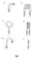
- a substantially L-shaped lamp is used such that the ink dots deposited by the upper half of the nozzles receive about twice the radiation dose compared to the lower part of the nozzles. Doing so avoids an increase of the overall power output level of the lamp which would be detrimental when printing on heat sensitive media and which would negatively influence power consumption and life time of the U V radiation system. Moreover, in the case of U V curing the energy that penetrates the deposited ink is a small portion of the energy that strikes the surface. Increasing the exposure time will increase the amount of energy that penetrates into the ink. The leg of the 'L' offers increased curing energy to the entire imaged area without any reduction in printing speed.
- Alternate shapes of the lamp can also be used including e.g. helical as in Fig.2b, circular as in Fig.2c, grid-like as in Fig.2d, candy cane as in Fig.2e.
- the dimensions and position, particular of the non-linear part of the lamp are chosen dependent on the size of the minimum advance of the image-receiving member, the direction of the advance, the number of printing stages and the minimum radiation dose required to completely or partially cure the deposited ink.
- the UV radiation system typically includes drive electronics such as e.g.
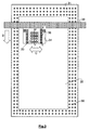
- the printing device of Fig.3 is an inkjet printer of the flatbed type suitable for printing with UV curable ink.
- the printing device comprises a flat support table (31) for supporting and fixing an image-receiving member (32). Underneath the table is a reservoir where air is maintained at a pressure well below atmospheric pressure.
- the support table includes a perforated metal plate having an upper surface contacting the image-receiving member or an intermediate support carrying the image-receiving member.
- the perforations (30) cause the image-receiving member or the intermediate support to be sucked against the surface of the table.
- the perforations (30) in the metal plate have typically a diameter of about 1 mm. Typically about 400 perforations per m2 are formed.
- larger recesses are formed having a diameter of about 5 mm, each recess surrounding a perforation.
- Several print heads (33), are mounted on a carriage (34) which can be moved in reciprocation along a guide member extending across the image-receiving member, i.e. the main scanning direction.
- the print heads (33) of a particular colour e.g. black (K), cyan (C), magenta (M), yellow (Y), are arranged in the main scanning direction, i.e. the direction indicated by double arrow C, while print heads of different colours are aligned substantially in the sub scanning direction as indicated by arrow D.
- Each print head comprises a number of discharging elements which are typically arranged in a single array or in multiple arrays in the sub scanning direction. Each discharging element is connected via an ink duet to an ink reservoir of the corresponding colour. Each ink duet is provided with means for activating the ink duet and an associated electrical drive circuit.
- the ink duet may be activated thermally, and/or piezoelectrically, or acoustic, or electrostatically.
- an ink drop is discharged form the discharge element in the direction of the table (31) and forms a dot of ink on the image-receiving member.
- the carriage further supports two radiation sources (38) for irradiating the ink dots deposited on the image-receiving member.
- the guide member may consist of two parallel cylindrical rods where the carriage is suspended on.
- the guide member and the carriage are both part of a gantry (39). This gantry can be moved back and forth along the image-receiving member, i.e. in the sub scanning direction.
- the support table (31) is kept stationary.
- the gantry In operation the gantry is first displaced to an initial printing position such as e.g. the upper left corner of the support table. Then, dependent upon the printing mode chosen, a print swath is formed by image-wise activating selected discharging elements of the print heads in relation to the pattern(s) of pixels of an image or document to be reproduced, while the carriage is moved across the image-receiving member.
- the radiation sources (38) schematically indicated in Fig.1 as element 8 irradiate at least the ink dots deposited during the print swath and overhang the print heads in the sub scanning direction.
- the print heads have a dimension E-E' in the sub-scanning direction greater than the width F-F' of image dots formed by the print heads on the image-receiving member in a traverse of the carriage across the image-receiving member.
- the radiation sources in casu L-shaped xenon flash lamps, are mounted to both sides of the carriage in such a way that all the ink jetted onto the image-receiving member is exposed to the radiation.
- the print heads are shielded to prohibit undesired exposure to UV irradiation.
- the lamp positioned upstream with respect to the print heads is instantly switched off when crossing the edge of the image-receiving member or the support table to avoid reflections from and/or heating up of the support table. Subsequently, in the reciprocating movement the same lamp is instantly switched on and when reaching the opposite edge of the image-receiving member the other lamp is switched off. By doing so, print quality degradation due to undesired UV back reflections or warming up of the image-receiving member is avoided or at least effectively limited. With UV curable inks there is a minimum dose of energy that is required to cure the ink.
- the swath of ink jetted in one traverse of the image-receiving member is typically much wider than the incremental advance of the carriage relative to the image-receiving member.
- the carriage is displaced in the sub scanning direction by displacing the gantry.
- ink discharged from one side of the carriage will be exposed to multiple doses of radiation while ink jetted from the opposite side will be exposed to fewer traverses of the lamps depending on the additional length of the overhang of the lamps.
- the L-shaped configuration of the lamps ensures that all the ink deposited receives at least a minimum radiation curing dose without increasing the output power level of the lamps.
- other non-linear shapes and/or other types of radiation source may also be used.
- the flatbed inkjet printer is alternately provided with two linear pulsed UV xenon lamps and two non-linear shaped pulsed UV xenon lamps of the same length mounted laterally adjacent the carriage.
- This printer is operated in a multiple printing stage mode where the incremental advance of the carriage in the sub scanning direction is smaller than a print swath width. This is to demonstrate the effect of introducing lamps shaped according to the present invention compared to linear shaped lamps on the radiation dose accumulated by the respective ink dots formed on the image-receiving member.
- the print swath width is 10.24 inches being also the total length F-F' of the nozzle array formed by the respective print heads.
- the dimension E-E' of each of the pulsed UV xenon lamps in the sub scanning direction is 14.5 inches and hence the lamps overhang the print heads.
- the overhang distance is 4.26 inches.
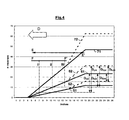
- the radiation dose received by the ink dots deposited on the image-receiving member and originating from the nozzles along the nozzle array F-F' is a factor of the number of times the lamps pass over the deposited ink. This number of traverses is depicted on the vertical axis of Fig.4 and depends on the printing mode and the advance increment of the carriage carrying the lamps and the print heads in the sub-scanning direction.
- the carriage is advanced in the sub scanning direction by advancing the gantry in direction D.
- the incremental advances in the sub-scanning direction are at least in an order of magnitude smaller than a print swath width, it is clear that the ink originating from the right hand side nozzles, i.e. the nozzles closer to position F', will accumulate a smaller dose of radiation energy than the ink originating from left hand side nozzles, i.e. the nozzles closer to position F.
- the radiation dose received by an ink dot in number of traverses can be converted into a radiation dose expressed in number of flashes by taking into account the size of the advance of the gantry, the flash rate of the lamps, e.g.
- Fig.4 an arbitrary position in the sub scanning direction of the carriage/ gantry with the print heads F-F including the nozzles, and the lamps E-E' is indicated with respect to the image-receiving member on the support table.
- the horizontal axis of Fig.4 depicts this position with respect to the image-receiving member in inches.
- the right hand side of the scale coincides with the start position of the gantry/carriage. The gantry will be advanced from right to the left, i.e. in the direction D.
- the radiation dose in number of traverses accumulated by each ink dot deposited dependent upon which nozzle it originates from is indicated for three different advance steps of the gantry, both with linear lamps (51)(61)(71) and with non-linear lamps (52)(62)(72).
- the maximum radiation dose which can be accumulated per ink dot deposited in case of linear lamps with gantry increments of 1.28 inches (51) is about 12 traverses.
- An ink dot which will be generated in the subsequent traverse of the carriage by a nozzle positioned near the center of the nozzle array of the multiple print heads, i.e., nozzle II, will accumulate a radiation dose D II,61 of about 14 traverses.
- An ink dot which will be generated in the subsequent traverse of the carriage by a nozzle positioned near the right hand side of the nozzle array of the multiple print heads, i.e. nozzle III, will accumulate a radiation dose D III,61 of about 8 traverses. Further, assuming that the lamp and carriage are driven such that a minimum radiation curing dose is required corresponding to 10 traverses.
- the ink dots to be generated in the subsequent traverse of the carriage by nozzles closely to the right hand side of the nozzle array, including the nozzle at position III will receive an insufficient radiation curing dose in case linear lamps are used.
- the non-linear lamps are shaped such that in the overhang region about twice the exposure time is generated compared to the linear lamps and by consequence an additional radiation dose will be received by all ink dots deposited.
- An ink dot which will be generated in the subsequent traverse of the carriage by a nozzle positioned near the center of the nozzle array of the multiple print heads, i.e. nozzle II, will accumulate a radiation dose D II,62 of about 22 traverses.
- An ink dot which will be generated in the subsequent traverse of the carriage by a nozzle positioned the right hand side of the nozzle array of the multiple print heads, i.e., nozzle III will accumulate a radiation dose D III,62 of about 17 traverses which is almost twice the radiation dose compared to D III,61 where linear lamps where used. Further assuming that the lamp and carriage are driven such that a minimum radiation curing dose is required corresponding t 10 traverses, all ink dot deposited will receive a sufficient curing dose.
Landscapes
- Health & Medical Sciences (AREA)
- General Health & Medical Sciences (AREA)
- Toxicology (AREA)
- Ink Jet (AREA)
- Vending Machines For Individual Products (AREA)
- Dot-Matrix Printers And Others (AREA)
- Treatments Of Macromolecular Shaped Articles (AREA)
Applications Claiming Priority (1)
| Application Number | Priority Date | Filing Date | Title |
|---|---|---|---|
| US10/921,801 US7261408B2 (en) | 2004-08-20 | 2004-08-20 | Printing device with radiation source |
Publications (3)
| Publication Number | Publication Date |
|---|---|
| EP1627746A2 true EP1627746A2 (de) | 2006-02-22 |
| EP1627746A3 EP1627746A3 (de) | 2008-03-05 |
| EP1627746B1 EP1627746B1 (de) | 2010-03-24 |
Family
ID=35134306
Family Applications (1)
| Application Number | Title | Priority Date | Filing Date |
|---|---|---|---|
| EP05076855A Ceased EP1627746B1 (de) | 2004-08-20 | 2005-08-10 | Druckvorrichtung mit Strahlungsquelle |
Country Status (5)
| Country | Link |
|---|---|
| US (1) | US7261408B2 (de) |
| EP (1) | EP1627746B1 (de) |
| JP (1) | JP2006056254A (de) |
| AT (1) | ATE461822T1 (de) |
| DE (1) | DE602005020094D1 (de) |
Cited By (3)
| Publication number | Priority date | Publication date | Assignee | Title |
|---|---|---|---|---|
| EP2955028A1 (de) * | 2014-06-12 | 2015-12-16 | Seiko Epson Corporation | Druckervorrichtung und druckverfahren |
| CN109760429A (zh) * | 2018-12-28 | 2019-05-17 | 青岛河钢复合新材料科技有限公司 | 数码印刷制造装置及其制造的印刷彩板加工工艺 |
| EP2520434B1 (de) * | 2011-05-02 | 2020-03-18 | Seiko Epson Corporation | Flüssigkeitsausstoßvorrichtung und Flüssigkeitsausstoßverfahren |
Families Citing this family (14)
| Publication number | Priority date | Publication date | Assignee | Title |
|---|---|---|---|---|
| ATE386642T1 (de) * | 2005-12-22 | 2008-03-15 | Tapematic Spa | Tintenstrahldruckapparat und verfahren |
| JP5139843B2 (ja) * | 2008-02-29 | 2013-02-06 | 株式会社ミマキエンジニアリング | インクジェットプリンタ及び印刷方法 |
| JP5128312B2 (ja) * | 2008-02-29 | 2013-01-23 | 株式会社ミマキエンジニアリング | 紫外線硬化型インクジェットプリンタ、紫外線硬化型インクジェットプリンタの印刷方法及びヘッドユニット構造 |
| US8342672B2 (en) * | 2008-03-24 | 2013-01-01 | Fuji Xerox Co., Ltd. | Recording apparatus |
| JP2010000712A (ja) * | 2008-06-20 | 2010-01-07 | Fuji Xerox Co Ltd | 画像記録用組成物、画像記録用インクセット、および記録装置 |
| JP5095640B2 (ja) * | 2009-01-15 | 2012-12-12 | 株式会社ミマキエンジニアリング | インクジェットプリンタおよびそれを用いた印刷方法 |
| GB0911015D0 (en) * | 2009-06-25 | 2009-08-12 | Sericol Ltd | Printing method |
| JP2011093181A (ja) * | 2009-10-29 | 2011-05-12 | Seiko Epson Corp | インクジェット記録装置のキャリッジ装置およびこれを備えたインクジェット記録装置 |
| US8573766B2 (en) * | 2011-09-16 | 2013-11-05 | Lumen Dynamics Group Inc. | Distributed light sources and systems for photo-reactive curing |
| US8646877B2 (en) * | 2011-09-29 | 2014-02-11 | Xerox Corporation | Pre-treatment methods, apparatus, and systems for contact leveling radiation curable gel inks |
| CN103213411A (zh) * | 2013-05-15 | 2013-07-24 | 济南优诺思喷印设备有限公司 | 用于3d图的打印机小车 |
| JP6311334B2 (ja) * | 2014-02-03 | 2018-04-18 | セイコーエプソン株式会社 | 液体吐出装置及び電磁波硬化型液体の硬化方法 |
| US10180248B2 (en) | 2015-09-02 | 2019-01-15 | ProPhotonix Limited | LED lamp with sensing capabilities |
| EP4338971B1 (de) * | 2022-09-19 | 2026-03-18 | Canon Production Printing Holding B.V. | Verfahren zur verbesserung der haftung einer uv-härtbaren tinte |
Family Cites Families (9)
| Publication number | Priority date | Publication date | Assignee | Title |
|---|---|---|---|---|
| US6786589B2 (en) * | 2002-03-27 | 2004-09-07 | Konica Corporation | Ink jet printer, ink jet head, and image forming method |
| JP2004001437A (ja) * | 2002-03-27 | 2004-01-08 | Konica Minolta Holdings Inc | インクジェットプリンタ、インク吐出ヘッドユニット及び画像形成方法 |
| JP2004001327A (ja) * | 2002-06-03 | 2004-01-08 | Mutoh Ind Ltd | インクジェット記録方法及び装置 |
| JP4483265B2 (ja) * | 2002-11-20 | 2010-06-16 | コニカミノルタホールディングス株式会社 | インクジェット記録装置 |
| JP2004203025A (ja) * | 2002-12-12 | 2004-07-22 | Konica Minolta Holdings Inc | 画像記録装置 |
| JP4269672B2 (ja) * | 2002-12-12 | 2009-05-27 | コニカミノルタホールディングス株式会社 | インクジェットプリンタ |
| ATE365642T1 (de) * | 2002-12-12 | 2007-07-15 | Luescher Hans | Druckvorrichtung und druckverfahren für uv- strahlungshärtbare tinte |
| JP2004188920A (ja) * | 2002-12-13 | 2004-07-08 | Konica Minolta Holdings Inc | インクジェットプリンタ |
| JP4203385B2 (ja) * | 2003-09-11 | 2008-12-24 | 東芝テック株式会社 | インクジェット用インク |
-
2004
- 2004-08-20 US US10/921,801 patent/US7261408B2/en not_active Expired - Lifetime
-
2005
- 2005-08-10 EP EP05076855A patent/EP1627746B1/de not_active Ceased
- 2005-08-10 AT AT05076855T patent/ATE461822T1/de not_active IP Right Cessation
- 2005-08-10 DE DE602005020094T patent/DE602005020094D1/de not_active Expired - Lifetime
- 2005-08-12 JP JP2005233990A patent/JP2006056254A/ja active Pending
Cited By (3)
| Publication number | Priority date | Publication date | Assignee | Title |
|---|---|---|---|---|
| EP2520434B1 (de) * | 2011-05-02 | 2020-03-18 | Seiko Epson Corporation | Flüssigkeitsausstoßvorrichtung und Flüssigkeitsausstoßverfahren |
| EP2955028A1 (de) * | 2014-06-12 | 2015-12-16 | Seiko Epson Corporation | Druckervorrichtung und druckverfahren |
| CN109760429A (zh) * | 2018-12-28 | 2019-05-17 | 青岛河钢复合新材料科技有限公司 | 数码印刷制造装置及其制造的印刷彩板加工工艺 |
Also Published As
| Publication number | Publication date |
|---|---|
| US7261408B2 (en) | 2007-08-28 |
| EP1627746A3 (de) | 2008-03-05 |
| EP1627746B1 (de) | 2010-03-24 |
| US20060038868A1 (en) | 2006-02-23 |
| DE602005020094D1 (de) | 2010-05-06 |
| JP2006056254A (ja) | 2006-03-02 |
| ATE461822T1 (de) | 2010-04-15 |
Similar Documents
| Publication | Publication Date | Title |
|---|---|---|
| EP1627746B1 (de) | Druckvorrichtung mit Strahlungsquelle | |
| JP5139843B2 (ja) | インクジェットプリンタ及び印刷方法 | |
| JP2002011860A (ja) | インクジェットプリンタ及びプリント方法 | |
| JP2009113284A (ja) | インクジェット記録装置 | |
| WO2011021403A1 (ja) | インクジェットプリンタおよびインクジェット印刷方法 | |
| EP2955028B1 (de) | Druckervorrichtung und druckverfahren | |
| JP4311491B2 (ja) | インクジェット記録装置及びインクジェット記録方法 | |
| JP2012096407A (ja) | インクジェット記録装置及び画像形成方法 | |
| JP2005103854A (ja) | インクジェット記録装置 | |
| JP2007237420A (ja) | インクジェット記録装置 | |
| JP2010131773A (ja) | ヘッド装置およびヘッド装置を有する装置 | |
| JP2004167793A (ja) | インクジェットプリンタ | |
| US20120176437A1 (en) | Recording apparatus | |
| EP3412471B1 (de) | Tintenstrahldruckeranordnung mit uv-bestrahlungssteuerung und verfahren zum betrieb dieser tintenstrahldruckeranordnung | |
| EP3415315B1 (de) | Bauvorrichtung und bauverfahren | |
| JP2005103852A (ja) | インクジェット記録装置 | |
| US20070103508A1 (en) | Inkjet recording apparatus | |
| JP4457622B2 (ja) | インクジェットプリンタ | |
| JP2006159499A (ja) | インクジェット記録装置 | |
| JP2008105268A (ja) | 光硬化型インクのインクジェット画像形成装置、及びインクジェット画像形成方法 | |
| JP4453269B2 (ja) | インクジェットプリンタ | |
| US12384171B2 (en) | Method for enhancing adhesion of a UV curable ink | |
| JP2010208217A (ja) | 印刷装置、及び、印刷方法 | |
| JP2007144773A (ja) | インクジェット記録装置 | |
| JP2010241145A (ja) | 光硬化型インクのインクジェット画像形成装置、及びインクジェット画像形成方法 |
Legal Events
| Date | Code | Title | Description |
|---|---|---|---|
| PUAI | Public reference made under article 153(3) epc to a published international application that has entered the european phase |
Free format text: ORIGINAL CODE: 0009012 |
|
| AK | Designated contracting states |
Kind code of ref document: A2 Designated state(s): AT BE BG CH CY CZ DE DK EE ES FI FR GB GR HU IE IS IT LI LT LU LV MC NL PL PT RO SE SI SK TR |
|
| AX | Request for extension of the european patent |
Extension state: AL BA HR MK YU |
|
| PUAL | Search report despatched |
Free format text: ORIGINAL CODE: 0009013 |
|
| AK | Designated contracting states |
Kind code of ref document: A3 Designated state(s): AT BE BG CH CY CZ DE DK EE ES FI FR GB GR HU IE IS IT LI LT LU LV MC NL PL PT RO SE SI SK TR |
|
| AX | Request for extension of the european patent |
Extension state: AL BA HR MK YU |
|
| 17P | Request for examination filed |
Effective date: 20080905 |
|
| AKX | Designation fees paid |
Designated state(s): AT BE BG CH CY CZ DE DK EE ES FI FR GB GR HU IE IS IT LI LT LU LV MC NL PL PT RO SE SI SK TR |
|
| 17Q | First examination report despatched |
Effective date: 20081017 |
|
| GRAP | Despatch of communication of intention to grant a patent |
Free format text: ORIGINAL CODE: EPIDOSNIGR1 |
|
| GRAS | Grant fee paid |
Free format text: ORIGINAL CODE: EPIDOSNIGR3 |
|
| GRAA | (expected) grant |
Free format text: ORIGINAL CODE: 0009210 |
|
| AK | Designated contracting states |
Kind code of ref document: B1 Designated state(s): AT BE BG CH CY CZ DE DK EE ES FI FR GB GR HU IE IS IT LI LT LU LV MC NL PL PT RO SE SI SK TR |
|
| REG | Reference to a national code |
Ref country code: GB Ref legal event code: FG4D |
|
| REG | Reference to a national code |
Ref country code: CH Ref legal event code: EP |
|
| REG | Reference to a national code |
Ref country code: IE Ref legal event code: FG4D |
|
| REF | Corresponds to: |
Ref document number: 602005020094 Country of ref document: DE Date of ref document: 20100506 Kind code of ref document: P |
|
| REG | Reference to a national code |
Ref country code: NL Ref legal event code: T3 |
|
| PG25 | Lapsed in a contracting state [announced via postgrant information from national office to epo] |
Ref country code: LT Free format text: LAPSE BECAUSE OF FAILURE TO SUBMIT A TRANSLATION OF THE DESCRIPTION OR TO PAY THE FEE WITHIN THE PRESCRIBED TIME-LIMIT Effective date: 20100324 |
|
| LTIE | Lt: invalidation of european patent or patent extension |
Effective date: 20100324 |
|
| PG25 | Lapsed in a contracting state [announced via postgrant information from national office to epo] |
Ref country code: SI Free format text: LAPSE BECAUSE OF FAILURE TO SUBMIT A TRANSLATION OF THE DESCRIPTION OR TO PAY THE FEE WITHIN THE PRESCRIBED TIME-LIMIT Effective date: 20100324 Ref country code: PL Free format text: LAPSE BECAUSE OF FAILURE TO SUBMIT A TRANSLATION OF THE DESCRIPTION OR TO PAY THE FEE WITHIN THE PRESCRIBED TIME-LIMIT Effective date: 20100324 Ref country code: LV Free format text: LAPSE BECAUSE OF FAILURE TO SUBMIT A TRANSLATION OF THE DESCRIPTION OR TO PAY THE FEE WITHIN THE PRESCRIBED TIME-LIMIT Effective date: 20100324 Ref country code: AT Free format text: LAPSE BECAUSE OF FAILURE TO SUBMIT A TRANSLATION OF THE DESCRIPTION OR TO PAY THE FEE WITHIN THE PRESCRIBED TIME-LIMIT Effective date: 20100324 Ref country code: FI Free format text: LAPSE BECAUSE OF FAILURE TO SUBMIT A TRANSLATION OF THE DESCRIPTION OR TO PAY THE FEE WITHIN THE PRESCRIBED TIME-LIMIT Effective date: 20100324 |
|
| PG25 | Lapsed in a contracting state [announced via postgrant information from national office to epo] |
Ref country code: RO Free format text: LAPSE BECAUSE OF FAILURE TO SUBMIT A TRANSLATION OF THE DESCRIPTION OR TO PAY THE FEE WITHIN THE PRESCRIBED TIME-LIMIT Effective date: 20100324 Ref country code: ES Free format text: LAPSE BECAUSE OF FAILURE TO SUBMIT A TRANSLATION OF THE DESCRIPTION OR TO PAY THE FEE WITHIN THE PRESCRIBED TIME-LIMIT Effective date: 20100705 Ref country code: SE Free format text: LAPSE BECAUSE OF FAILURE TO SUBMIT A TRANSLATION OF THE DESCRIPTION OR TO PAY THE FEE WITHIN THE PRESCRIBED TIME-LIMIT Effective date: 20100324 Ref country code: BE Free format text: LAPSE BECAUSE OF FAILURE TO SUBMIT A TRANSLATION OF THE DESCRIPTION OR TO PAY THE FEE WITHIN THE PRESCRIBED TIME-LIMIT Effective date: 20100324 Ref country code: EE Free format text: LAPSE BECAUSE OF FAILURE TO SUBMIT A TRANSLATION OF THE DESCRIPTION OR TO PAY THE FEE WITHIN THE PRESCRIBED TIME-LIMIT Effective date: 20100324 Ref country code: GR Free format text: LAPSE BECAUSE OF FAILURE TO SUBMIT A TRANSLATION OF THE DESCRIPTION OR TO PAY THE FEE WITHIN THE PRESCRIBED TIME-LIMIT Effective date: 20100625 |
|
| PG25 | Lapsed in a contracting state [announced via postgrant information from national office to epo] |
Ref country code: CZ Free format text: LAPSE BECAUSE OF FAILURE TO SUBMIT A TRANSLATION OF THE DESCRIPTION OR TO PAY THE FEE WITHIN THE PRESCRIBED TIME-LIMIT Effective date: 20100324 Ref country code: SK Free format text: LAPSE BECAUSE OF FAILURE TO SUBMIT A TRANSLATION OF THE DESCRIPTION OR TO PAY THE FEE WITHIN THE PRESCRIBED TIME-LIMIT Effective date: 20100324 Ref country code: IS Free format text: LAPSE BECAUSE OF FAILURE TO SUBMIT A TRANSLATION OF THE DESCRIPTION OR TO PAY THE FEE WITHIN THE PRESCRIBED TIME-LIMIT Effective date: 20100724 Ref country code: BG Free format text: LAPSE BECAUSE OF FAILURE TO SUBMIT A TRANSLATION OF THE DESCRIPTION OR TO PAY THE FEE WITHIN THE PRESCRIBED TIME-LIMIT Effective date: 20100624 |
|
| PLBE | No opposition filed within time limit |
Free format text: ORIGINAL CODE: 0009261 |
|
| STAA | Information on the status of an ep patent application or granted ep patent |
Free format text: STATUS: NO OPPOSITION FILED WITHIN TIME LIMIT |
|
| PG25 | Lapsed in a contracting state [announced via postgrant information from national office to epo] |
Ref country code: PT Free format text: LAPSE BECAUSE OF FAILURE TO SUBMIT A TRANSLATION OF THE DESCRIPTION OR TO PAY THE FEE WITHIN THE PRESCRIBED TIME-LIMIT Effective date: 20100726 Ref country code: DK Free format text: LAPSE BECAUSE OF FAILURE TO SUBMIT A TRANSLATION OF THE DESCRIPTION OR TO PAY THE FEE WITHIN THE PRESCRIBED TIME-LIMIT Effective date: 20100324 |
|
| 26N | No opposition filed |
Effective date: 20101228 |
|
| PG25 | Lapsed in a contracting state [announced via postgrant information from national office to epo] |
Ref country code: MC Free format text: LAPSE BECAUSE OF NON-PAYMENT OF DUE FEES Effective date: 20100831 Ref country code: IT Free format text: LAPSE BECAUSE OF FAILURE TO SUBMIT A TRANSLATION OF THE DESCRIPTION OR TO PAY THE FEE WITHIN THE PRESCRIBED TIME-LIMIT Effective date: 20100324 |
|
| REG | Reference to a national code |
Ref country code: CH Ref legal event code: PL |
|
| PG25 | Lapsed in a contracting state [announced via postgrant information from national office to epo] |
Ref country code: LI Free format text: LAPSE BECAUSE OF NON-PAYMENT OF DUE FEES Effective date: 20100831 Ref country code: CH Free format text: LAPSE BECAUSE OF NON-PAYMENT OF DUE FEES Effective date: 20100831 |
|
| PG25 | Lapsed in a contracting state [announced via postgrant information from national office to epo] |
Ref country code: IE Free format text: LAPSE BECAUSE OF NON-PAYMENT OF DUE FEES Effective date: 20100810 |
|
| PG25 | Lapsed in a contracting state [announced via postgrant information from national office to epo] |
Ref country code: CY Free format text: LAPSE BECAUSE OF FAILURE TO SUBMIT A TRANSLATION OF THE DESCRIPTION OR TO PAY THE FEE WITHIN THE PRESCRIBED TIME-LIMIT Effective date: 20100324 |
|
| PG25 | Lapsed in a contracting state [announced via postgrant information from national office to epo] |
Ref country code: LU Free format text: LAPSE BECAUSE OF NON-PAYMENT OF DUE FEES Effective date: 20100810 Ref country code: HU Free format text: LAPSE BECAUSE OF FAILURE TO SUBMIT A TRANSLATION OF THE DESCRIPTION OR TO PAY THE FEE WITHIN THE PRESCRIBED TIME-LIMIT Effective date: 20100925 |
|
| PG25 | Lapsed in a contracting state [announced via postgrant information from national office to epo] |
Ref country code: TR Free format text: LAPSE BECAUSE OF FAILURE TO SUBMIT A TRANSLATION OF THE DESCRIPTION OR TO PAY THE FEE WITHIN THE PRESCRIBED TIME-LIMIT Effective date: 20100324 |
|
| REG | Reference to a national code |
Ref country code: FR Ref legal event code: PLFP Year of fee payment: 12 |
|
| REG | Reference to a national code |
Ref country code: FR Ref legal event code: PLFP Year of fee payment: 13 |
|
| REG | Reference to a national code |
Ref country code: FR Ref legal event code: PLFP Year of fee payment: 14 |
|
| PGFP | Annual fee paid to national office [announced via postgrant information from national office to epo] |
Ref country code: NL Payment date: 20200728 Year of fee payment: 16 |
|
| PGFP | Annual fee paid to national office [announced via postgrant information from national office to epo] |
Ref country code: GB Payment date: 20200826 Year of fee payment: 16 Ref country code: FR Payment date: 20200821 Year of fee payment: 16 Ref country code: DE Payment date: 20200819 Year of fee payment: 16 |
|
| REG | Reference to a national code |
Ref country code: DE Ref legal event code: R119 Ref document number: 602005020094 Country of ref document: DE |
|
| REG | Reference to a national code |
Ref country code: NL Ref legal event code: MM Effective date: 20210901 |
|
| GBPC | Gb: european patent ceased through non-payment of renewal fee |
Effective date: 20210810 |
|
| PG25 | Lapsed in a contracting state [announced via postgrant information from national office to epo] |
Ref country code: NL Free format text: LAPSE BECAUSE OF NON-PAYMENT OF DUE FEES Effective date: 20210901 |
|
| PG25 | Lapsed in a contracting state [announced via postgrant information from national office to epo] |
Ref country code: GB Free format text: LAPSE BECAUSE OF NON-PAYMENT OF DUE FEES Effective date: 20210810 Ref country code: FR Free format text: LAPSE BECAUSE OF NON-PAYMENT OF DUE FEES Effective date: 20210831 Ref country code: DE Free format text: LAPSE BECAUSE OF NON-PAYMENT OF DUE FEES Effective date: 20220301 |