EP1628071B1 - Leuchteinheit für Kraftfahrzeuge - Google Patents
Leuchteinheit für Kraftfahrzeuge Download PDFInfo
- Publication number
- EP1628071B1 EP1628071B1 EP05107120.7A EP05107120A EP1628071B1 EP 1628071 B1 EP1628071 B1 EP 1628071B1 EP 05107120 A EP05107120 A EP 05107120A EP 1628071 B1 EP1628071 B1 EP 1628071B1
- Authority
- EP
- European Patent Office
- Prior art keywords
- light
- reflector
- segments
- segment
- disk
- Prior art date
- Legal status (The legal status is an assumption and is not a legal conclusion. Google has not performed a legal analysis and makes no representation as to the accuracy of the status listed.)
- Expired - Lifetime
Links
Images
Classifications
-
- F—MECHANICAL ENGINEERING; LIGHTING; HEATING; WEAPONS; BLASTING
- F21—LIGHTING
- F21S—NON-PORTABLE LIGHTING DEVICES; SYSTEMS THEREOF; VEHICLE LIGHTING DEVICES SPECIALLY ADAPTED FOR VEHICLE EXTERIORS
- F21S43/00—Signalling devices specially adapted for vehicle exteriors, e.g. brake lamps, direction indicator lights or reversing lights
- F21S43/40—Signalling devices specially adapted for vehicle exteriors, e.g. brake lamps, direction indicator lights or reversing lights characterised by the combination of reflectors and refractors
-
- F—MECHANICAL ENGINEERING; LIGHTING; HEATING; WEAPONS; BLASTING
- F21—LIGHTING
- F21S—NON-PORTABLE LIGHTING DEVICES; SYSTEMS THEREOF; VEHICLE LIGHTING DEVICES SPECIALLY ADAPTED FOR VEHICLE EXTERIORS
- F21S43/00—Signalling devices specially adapted for vehicle exteriors, e.g. brake lamps, direction indicator lights or reversing lights
- F21S43/30—Signalling devices specially adapted for vehicle exteriors, e.g. brake lamps, direction indicator lights or reversing lights characterised by reflectors
-
- F—MECHANICAL ENGINEERING; LIGHTING; HEATING; WEAPONS; BLASTING
- F21—LIGHTING
- F21S—NON-PORTABLE LIGHTING DEVICES; SYSTEMS THEREOF; VEHICLE LIGHTING DEVICES SPECIALLY ADAPTED FOR VEHICLE EXTERIORS
- F21S41/00—Illuminating devices specially adapted for vehicle exteriors, e.g. headlamps
- F21S41/30—Illuminating devices specially adapted for vehicle exteriors, e.g. headlamps characterised by reflectors
- F21S41/32—Optical layout thereof
- F21S41/33—Multi-surface reflectors, e.g. reflectors with facets or reflectors with portions of different curvature
- F21S41/337—Multi-surface reflectors, e.g. reflectors with facets or reflectors with portions of different curvature the reflector having a structured surface, e.g. with facets or corrugations
Definitions
- the invention relates to a lighting unit for motor vehicles.
- a lighting unit for motor vehicles which has a luminaire housing with a light source and a reflector. A light exit opening of the housing is closed by means of a cover. To produce a visual impression, the lighting unit will be operated by means of a plurality of LEDs, a pinhole with a plurality of openings is arranged between the reflector and the cover. By means of the reflector, a parallel light beam impinges on the pinhole, wherein only the part of the light beam is emitted, which passes through the openings of the pinhole.
- the disadvantage is that the known lighting unit has a reduced luminous efficacy.
- a light unit for motor vehicles with a light source with a reflector and a cover
- the reflector has a plurality of reflector segments.
- the reflector segments are designed such that they each have a common segment center with maximum illumination intensity. Each segment center thus has a bright point of light, which gives the impression of a light emitting diode as a light source.
- the reflector surfaces arranged around the segment center of the reflector segment are designed such that a predetermined light distribution is generated.
- the lens has a plurality of segments of the lens on, wherein a central lens segment plankonvex and distributed in the circumferential direction arranged light disc segments are formed meniscus-shaped.
- the reflector has a plurality of sector segments arranged reflector segments, which are each formed paraboloid-shaped. A radially outer portion of the reflector segment and a radially inner portion of the reflector segment are formed in such a way that the light reflected at the respective reflector segments only coincide in the area of the upstream light disk segment relative to an optical axis of the respective light disk segment.
- Object of the present invention is to develop a lighting unit for motor vehicles such that a modern LED styling with increased brilliance and high luminous efficacy is achieved.
- the invention has the features of claim 1.
- the particular advantage of the invention is that an increased brilliance of the LED styling is achieved by focusing light reflected by respective reflector segments onto corresponding upstream light disk segments.
- the basic idea of the invention is to provide light-disk segments in a light disk arranged in front of the reflector, in which light reflected by the reflector is bundled, so that the location of the light-disk segments has a maximum illumination intensity.
- a relatively bright point of light is created, which conveys the impression of a light diode downstream LED as a light source.
- a relatively large reflector surface can be used to focus the light in the respective lens segments.
- the light disk segments each have a lens structure, so that a predetermined light distribution is generated.
- the surfaces of the reflector segment essentially serve to bundle the light in the respectively assigned light disk segments, while the light disk segments themselves are designed to generate a predetermined light distribution.
- the main portion of the reflector segment extends at a distance from an optical axis of the lighting unit, which coincides with the distance of the associated light slice segment to the optical axis.
- the main light bundle reflected by the main section of the reflector segment is thus reflected substantially parallel to the optical axis in the direction of the light-emitting-disc segment.
- the main portion of the reflector segment is parabolic, wherein the light source is disposed at the focal point of the main portion.
- the main sections of the reflector segments extend - like the lens segments - in a circular ring about the optical axis, so that a circular LED styling is generated.
- a lighting unit according to the invention for motor vehicles is preferably used as a tail lamp for generating a brake light, taillight or a combination thereof.
- the lighting unit essentially comprises a light source 1, a reflector 2 associated with the light source 1, an optically-free cover 3 and a lens 4 arranged between the reflector 2 and the cover 3.
- the reflector 2 a plurality of circular sector-shaped reflector segments 5, each having a paraboloidal main section H and the other annular or teilnikringförmige secondary sections N on the one hand.
- the main sections H extend at an angle to an optical axis 8 of the lighting unit, on which a filament 9 of the formed as a light bulb 1 is located.
- the main sections H extend in an equal radial distance annularly about the optical axis 8, wherein to the main portion H radially outwardly side sections N 1, N 2, N 3 and N 4 large and radially inward side sections I1, I2, I3, I4 , I5, I6 and I7. How better FIG.
- the main sections H and the side sections N 1, N 2, N 3, N 4 are formed such that on the one hand from the arranged in the focal point of the main portion H filament 9 partial light beam h, which strikes the main portion H. , is reflected by the same parallel to the optical axis 8 in the direction of a light-emitting segment 10 of the lens 4.
- the light disk segments 10 are-like the main sections H -circular and extend concentrically in the circumferential direction of the lens 4, wherein they surround a central lens portion 11 having a scrubstrahloptik Medical.
- a prism structure 12 is applied to a side of the central lens section 11 facing away from the reflector 2.
- the lens segments 10 extend in a plane which is perpendicular to the optical axis 8.
- the principal portions H projected on the plane of extension of the lens 4 coincide in dimension with the lens segment 10.
- the light beam n 1 or i 1 impinging on the outer side sections N 1 and I 1 adjacent to the main section H are reflected in the direction of the parallel light beam h so that they meet with it in the region of the light pane segment 10.
- the light bundles n 4 and i 7 are shown are reflected at the corresponding subsections N 2, N 3, N 4, I 2, I 3, I 4, I 5, I 6, I 7 in the direction of the main light beam h , that they in the region of the upstream Lens segment 10 bundled become.
- a light-emitting diode or LED
- the reflector segments 5 arranged in the circumferential direction are each assigned a light-emitting-disc segment 10, which are distributed in a distributed manner around the optical axis 8 or the center axis of the lens 5.
- the light-emitting-disc segments 10 can each have a lens structure 13 which has the incident light h , n 1, n 2, n 3, n 4, i 1, i 2, i 3, i 4, i 5, i 6, i 7 corresponding to one scatter the given light distribution.
- a relatively small proportion of light preferably the light component emitted directly from the light source 1 to the front, is emitted to the outside through the central lens section 11.
- This light component which is emitted directly to the front, together with the central light section 11, brings about a homogenization of the luminous area caused by the light disk 4.
- the light-emitting-disc segments 10 on a side facing the reflector segment 5 can also have an optical structure 14 by means of which a specific light scattering can be generated.
- FIG. 2 joins the reflector segments 5 in Lichtabstrahlraum 15 a reflector tube 16, which has a corrugation 17 on an inner side.
- the corrugation 17 is used essentially for design purposes and is visible through the crystal clear cover 3 from the outside.
- the lens 4 is preferably colored red to produce a brake or tail light. But it can also be transparent.
- the main sections H or the secondary sections N 1, N 2, N 3, N 4, I 1, I 2, I 3, I 4, I 5, I 6, I 7 can also be designed as free-form surfaces. It is essential that the light incident on the same and emitted by a central light source 1 be bundled in a light-emitting-segment 10.
Landscapes
- Engineering & Computer Science (AREA)
- General Engineering & Computer Science (AREA)
- Non-Portable Lighting Devices Or Systems Thereof (AREA)
Description
- Die Erfindung betrifft eine Leuchteinheit für Kraftfahrzeuge.
- Aus der
DE 101 24 539 A1 ist eine Leuchteinheit für Kraftfahrzeuge bekannt, die ein Leuchtengehäuse mit einer Lichtquelle und einem Reflektor aufweist. Eine Lichtaustrittsöffnung des Gehäuses ist mittels einer Abdeckscheibe verschlossen. Zur Erzeugung eines optischen Eindrucks, die Leuchteinheit werde mittels einer Vielzahl von Leuchtdioden betrieben, ist zwischen dem Reflektor und der Abdeckscheibe eine Lochblende mit einer Mehrzahl von Öffnungen angeordnet. Vermittels des Reflektors trifft ein paralleles Lichtbündel auf die Lochblende, wobei nur der Teil des Lichtbündels abgestrahlt wird, der durch die Öffnungen der Lochblende hindurch tritt. Nachteilig weist somit die bekannte Leuchteinheit eine verringerte Lichtausbeute auf. - Aus der
DE 101 56 973 A1 ist eine Leuchteinheit für Kraftfahrzeuge mit einer Lichtquelle, mit einem Reflektor und einer Abdeckscheibe bekannt, wobei der Reflektor eine Mehrzahl von Reflektorsegmenten aufweist. Die Reflektorsegmente sind derart ausgebildet, dass sie jeweils ein gemeinsames Segmentzentrum mit maximaler Beleuchtungsintensität aufweisen. Jedes Segmentzentrum weist somit einen hellen Lichtpunkt auf, der den Eindruck einer Leuchtdiode als Lichtquelle vermittelt. Die um das Segmentzentrum herum angeordneten Reflektorflächen des Reflektorsegmentes sind derart ausgebildet, dass eine vorgegebene Lichtverteilung erzeugt wird. Nach der bekannten Leuchteinheit wird das gewünschte LED-Styling durch eine Lichtkonzentration in den Zentren der Reflektorsegmente erzeugt. - Aus der
US 6 364 514 B1 ist eine Leuchteinheit für Kraftfahrzeuge mit einer Lichtquelle, einem Reflektor und einer dem Reflektor vorgelagerten Lichtscheibe bekannt. Die Lichtscheibe weist eine Mehrzahl von Lichtscheibsegmenten auf, wobei ein zentrales Lichtscheibsegment plankonvex und in Umfangsrichtung verteilt angeordnete Lichtscheibsegmenten meniskusförmig ausgebildet sind. Der Reflektor weist eine Mehrzahl von kreissektorförmig angeordneten Reflektorsegmenten auf, die jeweils paraboloidförmig ausgebildet sind. Bezogen auf eine optische Achse des jeweils dem Reflektorsegment vorgelagerten Lichtscheibsegmentes ist ein in radialer Richtung äußerer Abschnitt des Reflektorsegmentes und ein in radialer Richtung innerer Abschnitt des Reflektorsegmentes derart ausgebildet, dass das an den jeweiligen Reflektorsegmenten reflektierte Licht lediglich im Bereich des vorgelagerten Lichtscheibsegmentes zusammentreffen. - Aufgabe der vorliegenden Erfindung ist es, eine Leuchteinheit für Kraftfahrzeuge derart weiterzubilden, dass ein modernes LED-Styling mit erhöhter Brillanz und hoher Lichtausbeute erzielt wird.
- Zur Lösung dieser Aufgabe weist die Erfindung die Merkmale des Patentanspruchs 1 auf.
- Der besondere Vorteil der Erfindung besteht darin, dass eine verstärkte Brillanz des LED-Stylings dadurch erzielt wird, dass von jeweiligen Reflektorsegmenten reflektiertes Licht auf korrespondierende vorgelagerte Lichtscheibsegmente fokussiert wird. Grundgedanke der Erfindung ist es, in einer dem Reflektor vorgelagerten Lichtscheibe Lichtscheibsegmente vorzusehen, in denen dass von dem Reflektor reflektierte Licht gebündelt wird, so dass der Ort der Lichtscheibsegmente eine maximale Beleuchtungsintensität aufweisen. In den Lichtscheibsegmenten entsteht somit ein relativ heller Lichtpunkt, der den Eindruck einer der Lichtscheibe nachgelagerten Leuchtdiode als Lichtquelle vermittelt. Vorteilhaft kann eine relativ große Reflektorfläche dazu genutzt werden, dass Licht in den jeweiligen Lichtscheibsegmenten zu bündeln.
- Nach einer Weiterbildung der Erfindung weisen die Lichtscheibsegmente jeweils eine Linsenstruktur auf, so dass eine vorgegebene Lichtverteilung erzeugt wird. Dabei dienen die Flächen des Reflektorsegmentes im Wesentlichen dazu, das Licht in den jeweils zugeordneten Lichtscheibsegmenten zu bündeln, während die Lichtscheibsegmente selbst derart ausgebildet sind, eine vorgegebene Lichtverteilung zu erzeugen.
- Nach einer Weiterbildung der Erfindung erstreckt sich der Hauptabschnitt des Reflektorsegmentes in einem Abstand zu einer optischen Achse der Leuchteinheit, der mit dem Abstand des zugeordneten Lichtscheibsegmentes zu der optischen Achse übereinstimmt. Das von dem Hauptabschnitt des Reflektorsegmentes reflektierte Hauptlichtbündel wird somit im Wesentlichen parallel zur optischen Achse in Richtung des Lichtscheibsegmentes reflektiert.
- Vorzugsweise ist der Hauptabschnitt des Reflektorsegmentes parabelförmig ausgebildet, wobei die Lichtquelle im Brennpunkt des Hauptabschnitts angeordnet ist. Die Hauptabschnitte der Reflektorsegmente erstrecken sich - wie die Lichtscheibsegmente - kreisringförmig um die optische Achse, so dass ein kreisförmiges LED-Styling erzeugt wird.
- Weitere Vorteile der Erfindung ergeben sich aus den weiteren Unteransprüchen.
- Ein Ausführungsbeispiel der Erfindung wird nachfolgend anhand der Zeichnungen näher erläutert.
- Es zeigen:
- Figur 1
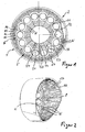
- eine Vorderansicht eines Reflektors der erfindungsgemäßen Leuchteinheit,
- Figur 2
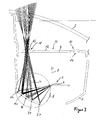
- eine perspektivische Ansicht des Reflektors seitlich von vorne,
- Figur 3
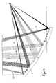
- einen Horizontalschnitt durch die Leuchteinheit ohne Darstellung einer Lichtquelle und
- Figur 4
- eine vergrößerte Darstellung einer Einzelheit X in
Figur 3 . - Eine erfindungsgemäße Leuchteinheit für Kraftfahrzeuge wird vorzugsweise als Heckleuchte eingesetzt zur Erzeugung eines Bremslichtes, Schlusslichtes oder einer Kombination derselben.
- Die Leuchteinheit weist im Wesentlichen eine Lichtquelle 1, einen der Lichtquelle 1 zugeordneten Reflektor 2, eine optikfreie Abdeckscheibe 3 sowie eine zwischen dem Reflektor 2 und der Abdeckscheibe 3 angeordnete Lichtscheibe 4 auf.
- Wie besser aus den
Figuren 1 und 2 zu ersehen ist, weist der Reflektor 2 eine Mehrzahl von kreissektorförmig angeordneten Reflektorsegmenten 5 auf, die jeweils zum einen einen paraboloidförmigen Hauptabschnitt H und zum anderen kreisringförmige bzw. teilkreisringförmige Nebenabschnitte N aufweisen. Wie ausFigur 2 zu ersehen ist, erstrecken sich die Hauptabschnitte H in einem Winkel zu einer optischen Achse 8 der Leuchteinheit, auf der eine Glühwendel 9 der als Glühlampe ausgebildeten Lichtquelle 1 liegt. Die Hauptabschnitte H erstrecken sich in einem gleichen radialen Abstand kreisringförmig um die optische Achse 8, wobei sich an den Hauptabschnitt H radial nach außen hin Nebenabschnitte N1, N2, N3 und groß N4 sowie radial nach innen hin Nebenabschnitte I1, I2, I3, I4, I5, I6 und I7 anschließen. Wie besser ausFigur 3 zu ersehen ist, sind die Hauptabschnitte H bzw. die Nebenabschnitte N1, N2, N3, N4 derart ausgebildet, dass zum einen ein von der im Brennpunkt des Hauptabschnitts H angeordnete Glühwendel 9 abgestrahltes Teillichtbündel h, das auf den Hauptabschnitt H trifft, von demselben parallel zur optischen Achse 8 in Richtung eines Lichtscheibsegmentes 10 der Lichtscheibe 4 reflektiert wird. Die Lichtscheibsegmente 10 sind - wie die Hauptabschnitte H - kreisförmig ausgebildet und erstrecken sich konzentrisch in Umfangsrichtung der Lichtscheibe 4, wobei sie einen zentralen Lichtscheibabschnitt 11 umgeben, der eine Rückstrahloptikstruktur aufweist. Zu diesem Zweck ist auf einer dem Reflektor 2 abgewandten Seite des zentralen Lichtscheibabschnitts 11 eine Prismenstruktur 12 aufgebracht. - Im vorliegenden Ausführungsführungsbeispiel erstrecken sich die Lichtscheibsegmente 10 in einer Ebene, die senkrecht zur optischen Achse 8 verläuft. Die auf die Erstreckungsebene der Lichtscheibe 4 projizierten Hauptabschnitte H stimmen in der Dimension mit dem Lichtscheibsegment 10 überein.
- Die auf den zum Hauptabschnitt H benachbart angeordneten äußeren Nebenabschnitte N1 und I1 auftreffenden Lichtstrahlbündel n1 bzw. i1 werden in Richtung des parallelen Lichtbündels h reflektiert, so dass sie im Bereich des Lichtscheibsegmentes 10 mit demselben zusammen treffen. Auch die weiteren auf die äußeren und inneren Nebenabschnitte N2, N3, N4, I2, I3, I4, I5, I6, I7 auftreffenden Teillichtbündel, von denen in
Figur 4 beispielhaft die Lichtbündel n4 sowie i7 dargestellt sind, werden an den entsprechenden Nebenabschnitten N2, N3, N4, I2, I3, I4, I5, I6, I7 derart in Richtung des Hauptlichtbündels h reflektiert, dass sie im Bereich des vorgelagerten Lichtscheibsegmentes 10 gebündelt werden. Auf diese Weise wird das gesamte vom Reflektorsegment 5 reflektierte Lichtbündel in dem Lichtscheibsegment 10 fokussiert mit der Wirkung, dass durch diese Lichtkonzentration der Anschein erweckt wird, dass hinter dem Lichtscheibsegment 10 als Lichtquelle eine Leuchtdiode (oder LED) angeordnet ist. - Den im Umfangsrichtung angeordneten Reflektorsegmenten 5 sind jeweils ein Lichtscheibsegment 10 zugeordnet, die konzentrisch verteilt um die optische Achse 8 bzw. der Mittelachse der Lichtscheibe 5 verteilt angeordnet sind. Die Lichtscheibsegmente 10 können jeweils eine Linsenstruktur 13 aufweisen, die das einfallende Licht h, n1, n2, n3, n4, i1, i2, i3, i4, i5, i6, i7 entsprechend einer vorgegebenen Lichtverteilung streuen. Ein relativ geringer Lichtanteil, vorzugsweise der direkt von der Lichtquelle 1 nach vorne abgestrahlte Lichtanteil, wird durch den zentralen Lichtscheibabschnitt 11 nach außen abgegeben. Dieser direkt nach vorne abgestrahlte Lichtanteil bewirkt zusammen mit dem zentralen Lichtabschnitt 11 eine Homogenisierung der durch die Lichtscheibe 4 bewirkten Leuchtfläche. Als im Wesentlichen Licht abgebende Fläche der Lichtscheibe 5 dienen lediglich die Lichtscheibsegmente 10.
- Wie aus
Figur 3 ersichtlich ist, können die Lichtscheibsegmente 10 auf einer dem Reflektorsegment 5 zugewandten Seite auch eine Optikstruktur 14 aufweisen, mittels der eine bestimmte Lichtstreuung erzeugt werden kann. - Wie aus
Figur 2 zu ersehen ist, schließt sich an die Reflektorsegmente 5 in Lichtabstrahlrichtung 15 ein Reflektortubus 16 an, der auf einer Innenseite eine Riffelung 17 aufweist. Die Riffelung 17 dient im Wesentlichen Designzwecken und ist durch die glasklare Abdeckscheibe 3 von außen sichtbar. - Die Lichtscheibe 4 ist vorzugsweise zur Erzeugung eines Brems- oder Schlusslichtes rot eingefärbt. Sie kann aber auch transparent ausgebildet sein.
- Nach einer nicht dargestellten alternativen Ausführungsform können die Hauptabschnitte H bzw. die Nebenabschnitte N1, N2, N3, N4, I1, I2, I3, I4, I5, I6, I7 auch als Freiformflächen ausgebildet sein. Wesentlich ist, dass das auf dieselben auftreffende und von einer zentralen Lichtquelle 1 ausgesandte Licht in einem Lichtscheibsegment 10 gebündelt wird.
Claims (6)
- Leuchteinheit für Kraftfahrzeuge mit einer Lichtquelle (1), mit einem der Lichtquelle (1) zugeordneten Reflektor (2) und mit einer eine vordere Öffnung des Reflektors (2) abdeckenden Abdeckscheibe (3), wobei der Reflektor (2) in eine Mehrzahl von kreissektorförmige Reflektorsegmente (5) unterteilt ist, dass dem Reflektor (2) eine Lichtscheibe (4) mit einer Mehrzahl von Lichtscheibsegmenten (10) vorgelagert ist, dass die Reflektorsegmente (5) jeweils den Lichtscheibsegmenten (10) zugeordnet und derart ausgebildet sind, dass an den Reflektorsegmenten (5) reflektierte Licht (h, n1, n2, n3, n4, i1, i2, i3, i4, i5, i6, i7) auf die jeweils zugeordneten Lichtscheibsegmente (10) gebündelt werden, dass das Reflektorsegment (5) zum einen einen paraboloidförmigen Hauptabschnitt (H) und zum anderen sich an den Hauptabschnitt (H) radial nach außen und radial nach innen nacheinander anschließende kreisringförmige oder teilkreisringförmige Nebenabschnitte (N1, N2, N3, N4, I1, I2, I3, I4, I5, I6, I7) aufweist, wobei die Hauptabschnitte sich in einem gleichen radialen Abstand kreisring förmig um eine optische Achse erstrecken, und wobei die Lichtscheibsegmente sich in einer Ebene erstrecken, die senkrecht zur optischen Achse verläuft, und wobei der auf die Erstreckungsebene der Lichtscheibe (4) projizierte Hauptabschnitt (H) mit der Dimension des Lichtscheibsegmentes (10) übereinstimmt und wobei die Nebenabschnitte (N1, N2, N3, N4, I1, I2, I3, I4, I5, I6, I7) des Reflektorsegmentes (5) derart ausgebildet sind, dass die von denselben reflektierten Nebenlichtbündel (n1, n2, n3, n4, i1, i2, i3, i4, i5, i6, i7) in dem vorgelagerten Lichtscheibensegment (10) zusammentreffen.
- Leuchteinheit nach Anspruch 1, dadurch gekennzeichnet, dass das Reflektorsegment (5) einen Hauptabschnitt (H) aufweist, derart, dass von dem Hauptabschnitt (H) das Licht (h) parallel zur optischen Achse (8) der Leuchteinheit in Richtung des vorgelagerten Lichtscheibsegmentes (10) reflektiert wird.
- Leuchteinheit nach Anspruch 1 oder 2, dadurch gekennzeichnet, dass die Nebenabschnitte (N1, N2, N3, N4, I1, I2, I3, I4, I5, 16, I7) rotationssymmetrisch zumindest teilweise um den Hauptabschnitt (H) herum verlaufend zu dem vorgelagerten Lichtscheibsegment (10) angeordnet sind.
- Leuchteinheit nach einem der Ansprüche 1 bis 3, dadurch gekennzeichnet, dass die Lichtscheibsegmente (10) kreisförmig ausgebildet sind und sich kreisringsförmig um einen zentralen Lichtscheibabschnitt (11) erstrecken, der eine Rückstrahloptikstruktur (12) aufweist.
- Leuchteinheit nach einem der Ansprüche 1 bis 4, dadurch gekennzeichnet, dass die Lichtscheibsegmente (10) eine Linsenstruktur aufweisen, derart, dass eine vorgegebene Lichtverteilung erzeugt wird.
- Leuchteinheit nach einem der Ansprüche 1 bis 5, dadurch gekennzeichnet, dass die Lichtquelle (1) als eine Glühlampe ausgebildet ist.
Applications Claiming Priority (1)
| Application Number | Priority Date | Filing Date | Title |
|---|---|---|---|
| DE102004040159A DE102004040159A1 (de) | 2004-08-19 | 2004-08-19 | Leuchteinheit für Kraftfahrzeuge |
Publications (3)
| Publication Number | Publication Date |
|---|---|
| EP1628071A2 EP1628071A2 (de) | 2006-02-22 |
| EP1628071A3 EP1628071A3 (de) | 2008-07-02 |
| EP1628071B1 true EP1628071B1 (de) | 2014-02-12 |
Family
ID=35427624
Family Applications (1)
| Application Number | Title | Priority Date | Filing Date |
|---|---|---|---|
| EP05107120.7A Expired - Lifetime EP1628071B1 (de) | 2004-08-19 | 2005-08-02 | Leuchteinheit für Kraftfahrzeuge |
Country Status (2)
| Country | Link |
|---|---|
| EP (1) | EP1628071B1 (de) |
| DE (1) | DE102004040159A1 (de) |
Families Citing this family (1)
| Publication number | Priority date | Publication date | Assignee | Title |
|---|---|---|---|---|
| DE102008019125B4 (de) * | 2008-04-16 | 2025-04-30 | Volkswagen Ag | Fahrzeugleuchte mit einer Lichtquelle, zwei Reflektoren, zwei Lichtscheiben mit jeweils einer Leuchtfläche und einer Maske zwischen den zwei Leuchtflächen, die eine direkte Sicht auf die Lichtquelle verhindert |
Family Cites Families (7)
| Publication number | Priority date | Publication date | Assignee | Title |
|---|---|---|---|---|
| JP3005954B2 (ja) * | 1998-04-10 | 2000-02-07 | スタンレー電気株式会社 | 灯 具 |
| JP2945376B1 (ja) * | 1998-05-01 | 1999-09-06 | スタンレー電気株式会社 | 灯 具 |
| JP3904783B2 (ja) * | 1999-11-30 | 2007-04-11 | 株式会社小糸製作所 | 車両用標識灯 |
| DE10124539B4 (de) * | 2001-05-19 | 2009-07-23 | Odelo Gmbh | Heckleuchte für Fahrzeuge, insbesondere für Kraftfahrzeuge |
| DE10156973A1 (de) * | 2001-11-20 | 2003-05-28 | Hella Kg Hueck & Co | Fahrzeugleuchte |
| DE10160052A1 (de) * | 2001-12-06 | 2003-06-18 | Hella Kg Hueck & Co | Fahrzeugleuchte |
| DE10219246A1 (de) * | 2002-04-18 | 2003-11-06 | Valeo Beleuchtung Deutschland | Beleuchtungseinrichtung für Kraftfahrzeuge |
-
2004
- 2004-08-19 DE DE102004040159A patent/DE102004040159A1/de not_active Withdrawn
-
2005
- 2005-08-02 EP EP05107120.7A patent/EP1628071B1/de not_active Expired - Lifetime
Also Published As
| Publication number | Publication date |
|---|---|
| EP1628071A2 (de) | 2006-02-22 |
| EP1628071A3 (de) | 2008-07-02 |
| DE102004040159A1 (de) | 2006-02-23 |
Similar Documents
| Publication | Publication Date | Title |
|---|---|---|
| DE102008003929B4 (de) | Fahrzeugleuchte | |
| DE10051464B4 (de) | Stufenlinse | |
| DE4342928C2 (de) | Relflektoranordnung mit einer darin angeordneten Lichtquelle für eine Fahrzeugleuchte | |
| AT510437B1 (de) | Led-lichtmodul und fahrzeugscheinwerfer | |
| EP2276969B1 (de) | Fahrzeugleuchte | |
| EP3473918B1 (de) | Beleuchtungsvorrichtung für einen kraftfahrzeugscheinwerfer | |
| DE102008036845B4 (de) | Beleuchtungsvorrichtung | |
| DE102012105095A1 (de) | Reflektorsignalleuchte mit verdeckter Lichtquelle | |
| EP2622261B1 (de) | Anordnung zur lichtabgabe | |
| EP1500868B1 (de) | Leuchtdioden-Modul für Fahrzeugscheinwerfer und Fahrzeugscheinwerfer | |
| DE102011111953A1 (de) | Tunnelleuchte | |
| DE102004011600A1 (de) | Rückstrahler für Heckleuchten von Fahrzeugen, vorzugsweise von Kraftfahrzeugen | |
| DE602004012797T2 (de) | Beleuchtungs- oder Signalisierungssystem für Fahrzeuge | |
| DE102011051541A1 (de) | Beleuchtungsvorrichtung für Fahrzeuge | |
| DE102018129989A1 (de) | Fahrzeugleuchte und Fahrzeug damit | |
| DE102006034324B4 (de) | Reflektor mit Prismenstruktur | |
| DE20311688U1 (de) | Scheinwerfer für ein Fahrzeug | |
| DE3035005C2 (de) | ||
| EP2253880B1 (de) | Leuchte für Fahrzeuge | |
| EP1628071A2 (de) | Leuchteinheit für Kraftfahrzeuge | |
| DE102007038205B4 (de) | Leuchte mit Lichtleiterplatte | |
| DE3115024C2 (de) | ||
| EP1362740B1 (de) | Fahrzeugleuchte | |
| DE102009005635B4 (de) | Beleuchtungsvorrichtung für Fahrzeuge | |
| EP2880360B1 (de) | Led-strahler |
Legal Events
| Date | Code | Title | Description |
|---|---|---|---|
| PUAI | Public reference made under article 153(3) epc to a published international application that has entered the european phase |
Free format text: ORIGINAL CODE: 0009012 |
|
| AK | Designated contracting states |
Kind code of ref document: A2 Designated state(s): AT BE BG CH CY CZ DE DK EE ES FI FR GB GR HU IE IS IT LI LT LU LV MC NL PL PT RO SE SI SK TR |
|
| AX | Request for extension of the european patent |
Extension state: AL BA HR MK YU |
|
| PUAL | Search report despatched |
Free format text: ORIGINAL CODE: 0009013 |
|
| AK | Designated contracting states |
Kind code of ref document: A3 Designated state(s): AT BE BG CH CY CZ DE DK EE ES FI FR GB GR HU IE IS IT LI LT LU LV MC NL PL PT RO SE SI SK TR |
|
| AX | Request for extension of the european patent |
Extension state: AL BA HR MK YU |
|
| 17P | Request for examination filed |
Effective date: 20081201 |
|
| 17Q | First examination report despatched |
Effective date: 20090130 |
|
| AKX | Designation fees paid |
Designated state(s): AT BE BG CH CY CZ DE DK EE ES FI FR GB GR HU IE IS IT LI LT LU LV MC NL PL PT RO SE SI SK TR |
|
| GRAP | Despatch of communication of intention to grant a patent |
Free format text: ORIGINAL CODE: EPIDOSNIGR1 |
|
| INTG | Intention to grant announced |
Effective date: 20130816 |
|
| GRAS | Grant fee paid |
Free format text: ORIGINAL CODE: EPIDOSNIGR3 |
|
| GRAA | (expected) grant |
Free format text: ORIGINAL CODE: 0009210 |
|
| AK | Designated contracting states |
Kind code of ref document: B1 Designated state(s): AT BE BG CH CY CZ DE DK EE ES FI FR GB GR HU IE IS IT LI LT LU LV MC NL PL PT RO SE SI SK TR |
|
| REG | Reference to a national code |
Ref country code: GB Ref legal event code: FG4D Free format text: NOT ENGLISH |
|
| REG | Reference to a national code |
Ref country code: CH Ref legal event code: EP Ref country code: DE Ref legal event code: R081 Ref document number: 502005014198 Country of ref document: DE Owner name: HELLA GMBH & CO. KGAA, DE Free format text: FORMER OWNER: HELLA KGAA HUECK & CO., 59557 LIPPSTADT, DE |
|
| REG | Reference to a national code |
Ref country code: AT Ref legal event code: REF Ref document number: 652305 Country of ref document: AT Kind code of ref document: T Effective date: 20140215 |
|
| REG | Reference to a national code |
Ref country code: IE Ref legal event code: FG4D Free format text: LANGUAGE OF EP DOCUMENT: GERMAN |
|
| REG | Reference to a national code |
Ref country code: DE Ref legal event code: R096 Ref document number: 502005014198 Country of ref document: DE Effective date: 20140327 |
|
| REG | Reference to a national code |
Ref country code: NL Ref legal event code: VDEP Effective date: 20140212 |
|
| REG | Reference to a national code |
Ref country code: LT Ref legal event code: MG4D |
|
| PG25 | Lapsed in a contracting state [announced via postgrant information from national office to epo] |
Ref country code: IS Free format text: LAPSE BECAUSE OF FAILURE TO SUBMIT A TRANSLATION OF THE DESCRIPTION OR TO PAY THE FEE WITHIN THE PRESCRIBED TIME-LIMIT Effective date: 20140612 Ref country code: LT Free format text: LAPSE BECAUSE OF FAILURE TO SUBMIT A TRANSLATION OF THE DESCRIPTION OR TO PAY THE FEE WITHIN THE PRESCRIBED TIME-LIMIT Effective date: 20140212 |
|
| PG25 | Lapsed in a contracting state [announced via postgrant information from national office to epo] |
Ref country code: CY Free format text: LAPSE BECAUSE OF FAILURE TO SUBMIT A TRANSLATION OF THE DESCRIPTION OR TO PAY THE FEE WITHIN THE PRESCRIBED TIME-LIMIT Effective date: 20140212 Ref country code: NL Free format text: LAPSE BECAUSE OF FAILURE TO SUBMIT A TRANSLATION OF THE DESCRIPTION OR TO PAY THE FEE WITHIN THE PRESCRIBED TIME-LIMIT Effective date: 20140212 Ref country code: SE Free format text: LAPSE BECAUSE OF FAILURE TO SUBMIT A TRANSLATION OF THE DESCRIPTION OR TO PAY THE FEE WITHIN THE PRESCRIBED TIME-LIMIT Effective date: 20140212 Ref country code: ES Free format text: LAPSE BECAUSE OF FAILURE TO SUBMIT A TRANSLATION OF THE DESCRIPTION OR TO PAY THE FEE WITHIN THE PRESCRIBED TIME-LIMIT Effective date: 20140212 Ref country code: PT Free format text: LAPSE BECAUSE OF FAILURE TO SUBMIT A TRANSLATION OF THE DESCRIPTION OR TO PAY THE FEE WITHIN THE PRESCRIBED TIME-LIMIT Effective date: 20140612 Ref country code: FI Free format text: LAPSE BECAUSE OF FAILURE TO SUBMIT A TRANSLATION OF THE DESCRIPTION OR TO PAY THE FEE WITHIN THE PRESCRIBED TIME-LIMIT Effective date: 20140212 |
|
| PG25 | Lapsed in a contracting state [announced via postgrant information from national office to epo] |
Ref country code: LV Free format text: LAPSE BECAUSE OF FAILURE TO SUBMIT A TRANSLATION OF THE DESCRIPTION OR TO PAY THE FEE WITHIN THE PRESCRIBED TIME-LIMIT Effective date: 20140212 |
|
| PG25 | Lapsed in a contracting state [announced via postgrant information from national office to epo] |
Ref country code: EE Free format text: LAPSE BECAUSE OF FAILURE TO SUBMIT A TRANSLATION OF THE DESCRIPTION OR TO PAY THE FEE WITHIN THE PRESCRIBED TIME-LIMIT Effective date: 20140212 Ref country code: DK Free format text: LAPSE BECAUSE OF FAILURE TO SUBMIT A TRANSLATION OF THE DESCRIPTION OR TO PAY THE FEE WITHIN THE PRESCRIBED TIME-LIMIT Effective date: 20140212 Ref country code: CZ Free format text: LAPSE BECAUSE OF FAILURE TO SUBMIT A TRANSLATION OF THE DESCRIPTION OR TO PAY THE FEE WITHIN THE PRESCRIBED TIME-LIMIT Effective date: 20140212 Ref country code: RO Free format text: LAPSE BECAUSE OF FAILURE TO SUBMIT A TRANSLATION OF THE DESCRIPTION OR TO PAY THE FEE WITHIN THE PRESCRIBED TIME-LIMIT Effective date: 20140212 |
|
| REG | Reference to a national code |
Ref country code: DE Ref legal event code: R097 Ref document number: 502005014198 Country of ref document: DE |
|
| PG25 | Lapsed in a contracting state [announced via postgrant information from national office to epo] |
Ref country code: PL Free format text: LAPSE BECAUSE OF FAILURE TO SUBMIT A TRANSLATION OF THE DESCRIPTION OR TO PAY THE FEE WITHIN THE PRESCRIBED TIME-LIMIT Effective date: 20140212 Ref country code: SK Free format text: LAPSE BECAUSE OF FAILURE TO SUBMIT A TRANSLATION OF THE DESCRIPTION OR TO PAY THE FEE WITHIN THE PRESCRIBED TIME-LIMIT Effective date: 20140212 |
|
| PLBE | No opposition filed within time limit |
Free format text: ORIGINAL CODE: 0009261 |
|
| STAA | Information on the status of an ep patent application or granted ep patent |
Free format text: STATUS: NO OPPOSITION FILED WITHIN TIME LIMIT |
|
| 26N | No opposition filed |
Effective date: 20141113 |
|
| REG | Reference to a national code |
Ref country code: DE Ref legal event code: R097 Ref document number: 502005014198 Country of ref document: DE Effective date: 20141113 |
|
| PG25 | Lapsed in a contracting state [announced via postgrant information from national office to epo] |
Ref country code: LU Free format text: LAPSE BECAUSE OF FAILURE TO SUBMIT A TRANSLATION OF THE DESCRIPTION OR TO PAY THE FEE WITHIN THE PRESCRIBED TIME-LIMIT Effective date: 20140802 Ref country code: IT Free format text: LAPSE BECAUSE OF FAILURE TO SUBMIT A TRANSLATION OF THE DESCRIPTION OR TO PAY THE FEE WITHIN THE PRESCRIBED TIME-LIMIT Effective date: 20140212 Ref country code: MC Free format text: LAPSE BECAUSE OF FAILURE TO SUBMIT A TRANSLATION OF THE DESCRIPTION OR TO PAY THE FEE WITHIN THE PRESCRIBED TIME-LIMIT Effective date: 20140212 |
|
| REG | Reference to a national code |
Ref country code: CH Ref legal event code: PL |
|
| GBPC | Gb: european patent ceased through non-payment of renewal fee |
Effective date: 20140802 |
|
| PG25 | Lapsed in a contracting state [announced via postgrant information from national office to epo] |
Ref country code: LI Free format text: LAPSE BECAUSE OF NON-PAYMENT OF DUE FEES Effective date: 20140831 Ref country code: BE Free format text: LAPSE BECAUSE OF NON-PAYMENT OF DUE FEES Effective date: 20140831 Ref country code: CH Free format text: LAPSE BECAUSE OF NON-PAYMENT OF DUE FEES Effective date: 20140831 |
|
| REG | Reference to a national code |
Ref country code: IE Ref legal event code: MM4A |
|
| PG25 | Lapsed in a contracting state [announced via postgrant information from national office to epo] |
Ref country code: SI Free format text: LAPSE BECAUSE OF FAILURE TO SUBMIT A TRANSLATION OF THE DESCRIPTION OR TO PAY THE FEE WITHIN THE PRESCRIBED TIME-LIMIT Effective date: 20140212 |
|
| REG | Reference to a national code |
Ref country code: FR Ref legal event code: ST Effective date: 20150430 |
|
| PG25 | Lapsed in a contracting state [announced via postgrant information from national office to epo] |
Ref country code: GB Free format text: LAPSE BECAUSE OF NON-PAYMENT OF DUE FEES Effective date: 20140802 |
|
| PG25 | Lapsed in a contracting state [announced via postgrant information from national office to epo] |
Ref country code: IE Free format text: LAPSE BECAUSE OF NON-PAYMENT OF DUE FEES Effective date: 20140802 Ref country code: FR Free format text: LAPSE BECAUSE OF NON-PAYMENT OF DUE FEES Effective date: 20140901 |
|
| REG | Reference to a national code |
Ref country code: AT Ref legal event code: MM01 Ref document number: 652305 Country of ref document: AT Kind code of ref document: T Effective date: 20140802 |
|
| PG25 | Lapsed in a contracting state [announced via postgrant information from national office to epo] |
Ref country code: AT Free format text: LAPSE BECAUSE OF NON-PAYMENT OF DUE FEES Effective date: 20140802 |
|
| PG25 | Lapsed in a contracting state [announced via postgrant information from national office to epo] |
Ref country code: BG Free format text: LAPSE BECAUSE OF FAILURE TO SUBMIT A TRANSLATION OF THE DESCRIPTION OR TO PAY THE FEE WITHIN THE PRESCRIBED TIME-LIMIT Effective date: 20140212 |
|
| PG25 | Lapsed in a contracting state [announced via postgrant information from national office to epo] |
Ref country code: GR Free format text: LAPSE BECAUSE OF FAILURE TO SUBMIT A TRANSLATION OF THE DESCRIPTION OR TO PAY THE FEE WITHIN THE PRESCRIBED TIME-LIMIT Effective date: 20140513 |
|
| PG25 | Lapsed in a contracting state [announced via postgrant information from national office to epo] |
Ref country code: TR Free format text: LAPSE BECAUSE OF FAILURE TO SUBMIT A TRANSLATION OF THE DESCRIPTION OR TO PAY THE FEE WITHIN THE PRESCRIBED TIME-LIMIT Effective date: 20140212 Ref country code: HU Free format text: LAPSE BECAUSE OF FAILURE TO SUBMIT A TRANSLATION OF THE DESCRIPTION OR TO PAY THE FEE WITHIN THE PRESCRIBED TIME-LIMIT; INVALID AB INITIO Effective date: 20050802 |
|
| REG | Reference to a national code |
Ref country code: DE Ref legal event code: R082 Ref document number: 502005014198 Country of ref document: DE Representative=s name: FIEDLER, OSTERMANN & SCHNEIDER - PATENTANWAELT, DE Ref country code: DE Ref legal event code: R082 Ref document number: 502005014198 Country of ref document: DE Representative=s name: PATENTANWAELTE FIEDLER, OSTERMANN & SCHNEIDER, DE Ref country code: DE Ref legal event code: R081 Ref document number: 502005014198 Country of ref document: DE Owner name: HELLA GMBH & CO. KGAA, DE Free format text: FORMER OWNER: HELLA KGAA HUECK & CO., 59557 LIPPSTADT, DE |
|
| PGFP | Annual fee paid to national office [announced via postgrant information from national office to epo] |
Ref country code: DE Payment date: 20200722 Year of fee payment: 16 |
|
| REG | Reference to a national code |
Ref country code: DE Ref legal event code: R119 Ref document number: 502005014198 Country of ref document: DE |
|
| PG25 | Lapsed in a contracting state [announced via postgrant information from national office to epo] |
Ref country code: DE Free format text: LAPSE BECAUSE OF NON-PAYMENT OF DUE FEES Effective date: 20220301 |