EP1628073A2 - Vanne d'une installation de purification de gaz d'échappement et installation de purification de gaz d'échappement - Google Patents
Vanne d'une installation de purification de gaz d'échappement et installation de purification de gaz d'échappement Download PDFInfo
- Publication number
- EP1628073A2 EP1628073A2 EP05107632A EP05107632A EP1628073A2 EP 1628073 A2 EP1628073 A2 EP 1628073A2 EP 05107632 A EP05107632 A EP 05107632A EP 05107632 A EP05107632 A EP 05107632A EP 1628073 A2 EP1628073 A2 EP 1628073A2
- Authority
- EP
- European Patent Office
- Prior art keywords
- valve
- closure body
- exhaust gas
- shaft
- valve seat
- Prior art date
- Legal status (The legal status is an assumption and is not a legal conclusion. Google has not performed a legal analysis and makes no representation as to the accuracy of the status listed.)
- Granted
Links
Images




Classifications
-
- F—MECHANICAL ENGINEERING; LIGHTING; HEATING; WEAPONS; BLASTING
- F23—COMBUSTION APPARATUS; COMBUSTION PROCESSES
- F23G—CREMATION FURNACES; CONSUMING WASTE PRODUCTS BY COMBUSTION
- F23G7/00—Incinerators or other apparatus for consuming industrial waste, e.g. chemicals
- F23G7/06—Incinerators or other apparatus for consuming industrial waste, e.g. chemicals of waste gases or noxious gases, e.g. exhaust gases
- F23G7/061—Incinerators or other apparatus for consuming industrial waste, e.g. chemicals of waste gases or noxious gases, e.g. exhaust gases with supplementary heating
- F23G7/065—Incinerators or other apparatus for consuming industrial waste, e.g. chemicals of waste gases or noxious gases, e.g. exhaust gases with supplementary heating using gaseous or liquid fuel
- F23G7/066—Incinerators or other apparatus for consuming industrial waste, e.g. chemicals of waste gases or noxious gases, e.g. exhaust gases with supplementary heating using gaseous or liquid fuel preheating the waste gas by the heat of the combustion, e.g. recuperation type incinerator
- F23G7/068—Incinerators or other apparatus for consuming industrial waste, e.g. chemicals of waste gases or noxious gases, e.g. exhaust gases with supplementary heating using gaseous or liquid fuel preheating the waste gas by the heat of the combustion, e.g. recuperation type incinerator using regenerative heat recovery means
-
- B—PERFORMING OPERATIONS; TRANSPORTING
- B01—PHYSICAL OR CHEMICAL PROCESSES OR APPARATUS IN GENERAL
- B01D—SEPARATION
- B01D53/00—Separation of gases or vapours; Recovering vapours of volatile solvents from gases; Chemical or biological purification of waste gases, e.g. engine exhaust gases, smoke, fumes, flue gases, aerosols
- B01D53/34—Chemical or biological purification of waste gases
- B01D53/74—General processes for purification of waste gases; Apparatus or devices specially adapted therefor
Definitions
- the present invention relates to a valve for a thermal-regenerative emission control system according to the preamble of claim 1 and a thermal-regenerative emission control system with at least one such valve.
- Such emission control systems are used for removing volatile hydrocarbon-containing substances and other organic volatile constituents, such as odors, from exhaust gases or the exhaust air of industrial or craft processes or facilities.
- the temperature of the exhaust gas, wherein the volatile organic substances are contained is heated by means of a suitable heat exchanger before being admitted into a combustion chamber at a temperature of about 750 ° C, there to perform a thermal oxidation.
- thermal-regenerative exhaust gas purification most of the heat of combustion emitted during oxidation is stored in a solid storage medium, for example in a ceramic material. The stored heat then takes on the process or exhaust gas to be oxidized (following in the process cycle), the heat exchanger serving exclusively for in-process heat recovery.
- the process is autothermal or requires additional energy.
- valves in continuous operation are required for optimal and future legal requirements sufficient exhaust gas purification.
- a transfer of still untreated exhaust gases into a gas outlet pipe of the emission control system can be prevented only with hermetically locking valves.
- the use of sealing rings and the like in the valve seat has proven to be insufficient for continuous operation in thermal-regenerative emission control systems, in particular also with regard to the fact that long replacement intervals are desired.
- hermetically locking valves can be formed in a particularly simple manner by forming a conical valve seat in a valve housing which cooperates with a correspondingly designed conical valve body.
- the sealing ability of valves in thermal-regenerative emission control systems is impaired by dirt deposits as well as by mechanical damage in the region of the valve seat and the associated closure body. Mechanical damage to the valve seat and / or closure body can also be the direct result of dirt deposits in these areas. It is known that dirt deposits tend to accumulate locally, which further promotes leaks in hermetically sealed valves.
- a conical valve seat is disclosed in FR 707,275 and FR 679,464, in which open a plurality of radial bores, which are in communication with a fan or compressed air generator.
- a purge gas flows from the radial bores into the annular gap between the closure body and the conical valve seat 1 in order to rinse the valve seat and the closure body and to remove dirt deposits.
- a valve according to the preamble of claim 1 having a conical valve seat is disclosed in EP 1 258 678 A2.
- a plurality of radial bores open at a distance one another in the valve seat.
- a circumferential groove is provided in the valve seat into which the plurality of radial bores open and which distributes the purge gas uniformly in the circumferential direction.
- the structure of the valve with a plurality of radial bores is relatively expensive. If the multiple radial bores are to be connected to an external fan, then a complex pipe system is required. The effect of the purge gas during closing of the valve is also not uniform. Because the rinsing effect is influenced by the width of the annular gap between the valve seat and the closure body, so that the cleaning effect of the purge gas also depends on the position of the adjusting body.
- DE 201 18 418 U1 discloses an exhaust air purification device for the thermal and / or catalytic purification of exhaust air containing combustible components.
- poppet valves are used, the valve body is movable by means of a movement device between a closed position and an open position.
- the poppet valve in each case has an annular valve seat surrounding the access opening and a circular disk-shaped valve body covering the access opening. Particles in the raw gas stream can lead to a deposit in the region of the valve seat, which may affect the tightness of the poppet valves.
- DE 197 20 205 A1 discloses a method and a system for purifying exhaust gases laden with nitrogen oxides.
- globe valves are used comparable to the poppet valves according to DE 201 18 418 U1.
- No. 5,134,945 discloses a thermal-regenerative emission control system with valves designed in the manner of flat slides. Particles in the exhaust air flow to be cleaned can likewise lead to deposits in the region of the valve seat, as in the case of the abovementioned valve types, so that hermetic tightness of the valves can not be ensured here as well, especially not in continuous operation.
- WO 89/06763 discloses a method and apparatus for protecting and supporting a seal of a valve device.
- a circumferential seal is received in a groove which seals in the closed position against the valve seat.
- a closure part Above the valve seat is located almost in extension of the valve seat, a closure part.
- valve body circumferential seals on the outer peripheral edge of the valve body, wherein in the annular gap between the two circumferential seals opens a formed in the valve body flow channel, for leakage discharge and / or cleaning agent removal.
- the use of sealing rings and the like in the valve seat for the continuous operation of thermal-regenerative emission control systems is not satisfactory, especially with regard to the invention long replacement intervals should be sought.
- Object of the present invention is to provide a valve for a thermal-regenerative emission control system in a simple and cost-effective manner. According to a further aspect of the present invention, such a valve is to be provided, in which the valve seat is freed uniformly from dirt deposits. According to a further aspect of the present invention, it is also intended to provide a thermal-regenerative emission control system with at least one such valve.
- the invention relates to a valve for a thermal-regenerative emission control system, which is insertable into a connecting pipe of the exhaust gas purification system, which connects a gas inlet or outlet pipe for the entry or exit of an untreated or treated exhaust gas with a treatment chamber, with a conical valve seat and a correspondingly formed closure body to close an opening formed by the valve seat, wherein the closure body is connected to an axially movable shaft in order to adjust the closure body.
- the valve is characterized in that the closure body comprises an upper closure body plate and a lower closure body plate, which are spaced from each other, wherein the shaft has an axial inner bore which is connected to a space formed between the closure body plates to the space directly with the outside environment or to connect to an external blower or compressed air generator.
- the valve seat has an advantageously simple structure, with a bevelled inner peripheral edge, in which no groove or the like needs to be formed.
- the production cost is low, fall in the production of no disturbing burrs that could affect the tightness of the valve, and a hermetic tightness of the valve in continuous operation is readily possible.
- no expensive piping system is required to supply the valve seat purging air from an external blower or a compressed air generator.
- the gap can be controlled very precisely. In particular, this can also be made very narrow, so that scavenging air can be injected very controlled in the valve seat.
- the entire area of the valve seat can be rinsed uniformly, so that dirt deposits and the like on the valve seat can be removed even more effectively. Due to gravity, dirt deposits will mostly deposit on the obliquely downwardly inclined inner peripheral edge of the valve seat, but not on the bevelled peripheral edges of the closure body plates. The scavenging air emerging radially outward from the intermediate space between the two closure body plates is therefore sufficient for removing dirt deposits in the valve region.
- the gap When operated with negative pressure exhaust gas cleaning systems, the gap also contributes in a particularly effective manner to a hermetic tightness of the valve. Because the space connected via the inner bore of the valve stem with the outside environment or with an external blower or a compressed air generator is below a certain extent both with respect to the region above the closure body and with respect to the region below the closure body, ie with respect to the gas inlet or gas outlet tube overpressure. Therefore, in the event of possible leaks at the peripheral edge of the upper and / or lower closure body plate, purge air will flow from the gap via the leak into the region above the closure body and / or below the closure body, effectively effecting direct gas exchange between the regions above and below the closure body is excluded.
- the flow resistance of the intermediate space can be predetermined by a suitable choice of the height of the intermediate space in an advantageously simple manner.
- an opening may be provided at a lower end of the stem protruding from the gas inlet or gas outlet tube to connect the inner bore of the valve stem to the outside environment or to the external blower or compressed air generator.
- This opening may be provided directly in the peripheral wall of the valve stem or formed directly through the inner bore of the valve stem.
- a closure plate in which the opening is formed, preferably centrally.
- the end plate is formed at the lower end of the valve stem of a hardened metal, so that a cam-like, vertically movable adjusting element can be used for adjusting the valve stem and the closure body.
- a cam-like, vertically movable adjusting element can be used for adjusting the valve stem and the closure body.
- the valve stem or the end plate located at its lower end is permanently pressed against the movable adjusting element due to gravity.
- the adjusting element cooperates with the lower end of the valve stem or the end plate such that upon adjustment of the valve stem, a rotational drive force is generated which slowly rotates the stem and the closure body connected thereto. It is advantageous that the valve seat and the closure body formed from the plates are worn more evenly. Furthermore, due to the slow rotational movement, it is avoided that always the same areas of the valve seat and the closure body plates come into abutment in order to close the opening in the valve seat. Thus, it can be avoided according to the invention that mechanical damage, material defects and the like increase more and more locally until the valve becomes leaky in areas where the mechanical damage, material defects and the like have increased greatly in continuous operation.
- the adjusting element can interact eccentrically with the lower end of the valve stem or the end plate and / or can be provided at the lower end of the valve stem or on the end plate or on the upper side of the adjusting element bevelled and / or curved surfaces.
- a roller or a rolling element is provided on the upper side of the adjusting element, in order to cause the aforementioned rotational movement of the valve stem and the closure body.
- These openings may be formed, for example, as peripheral slots. According to a preferred variant, it suffices to provide a single opening at the upper end of the valve stem, which further reduces the manufacturing costs.
- the closure body plates are connected to each other by means of a plurality of connecting elements, which are arranged in the intermediate space near the peripheral edges of the closure body plates. It is advantageous that, because the closure body plates on the short distance between the externally arranged connecting elements and the outer peripheral edges can bend very little, that the positional relationship between the tapered peripheral edges of the closure body plates can be precisely specified, so that a hermetic tightness of the valve in a simple Way.
- the plurality of connecting elements is arranged point-symmetrically with respect to the shaft, so that any strains or mechanical loads can be evenly distributed on the closure body and the positional relationship of the important for the hermetic tightness of the valve peripheral edges can remain virtually unchanged.
- thermo-regenerative / exhaust gas-emission control system which is characterized by at least one valve according to the invention, which is hermetically sealed in order to prevent unwanted transfer of untreated exhaust gas into the gas outlet pipe ,
- valves are driven by means of a central drive shaft to lock or regulate the exhaust gas flow in the exhaust gas purification system suitable.
- identical reference numerals designate identical or essentially identically acting elements or groups of elements.
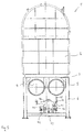
- Fig. 1 shows a schematic side view of a thermal-regenerative emission control system according to the present invention.
- the exhaust gas purification system 1 comprises a plurality, preferably an odd number, of treatment chambers 2, which are connected via a respective vertical connection pipe 3 to a gas inlet pipe 4 and a gas outlet pipe 5, respectively (see FIG. Below the gas inlet pipe 4, a plurality of bearing blocks 41 are arranged, in association with a treatment chamber 2, which support a central drive shaft 40 and a respective gear to convert the rotational movement of the drive shaft 40 in a vertical adjusting force for raising and lowering the valve stems 20, which follows will be described in more detail with reference to Figures 4-6.
- valve stem 20 projects out of the gas inlet pipe 4.
- the valve stem 20 is movably mounted in sealing sleeves (see Fig. 4) in order to open and close the valve 10 by lifting and lowering the two closure body plates 14, 15 forming a closure body. In this way, an exhaust gas flow can be blocked and regulated in the emission control system.
- the valve generally designated by the reference numeral 10 is inserted into a vertical connecting pipe 3, in the transition region between the associated gas inlet pipe 4 (or gas outlet pipe 5) and the associated treatment chamber.
- the emission control system 1 is elevated to a frame 6, which is stiffened with cross braces 7 and whose height is selected so that the drive 41 for adjusting the valve stems 20 can be arranged directly below the emission control system 1 and also Maintenance work below the emission control system can be performed easily.
- the valve 10 includes a valve seat 11, a closure body formed in the illustrated embodiment of two closure body plates 14, 15, and the valve stem 20 for raising and lowering the closure body to open the opening formed by the valve seat 11 and close.
- the valve seat 11 is sealed by means of flange connections (not shown) in the vertical connecting pipe 3.
- the valve seat 11 has a flat underside 12 for connecting, receiving or forming a flange, and at an acute angle, which is approximately 60 degrees in the illustrated embodiment, obliquely upward valve seat surface 13.
- the valve seat surface 13 forms an upwardly open , conical valve seat, with a flat, featureless inner peripheral edge, which points diagonally upwards.
- the valve closure body comprises two closure body plates 14, 15 arranged in parallel, which are rigidly connected to one another by means of connecting elements 17. Between the two closure body plates 14, 15, a narrow gap or gap 16 is formed, whose height is predetermined by the connecting elements 17 and in the illustrated example, significantly smaller than the thickness of the closure body plates 14, 15.
- the outer peripheral edges 18, 19 of the closure body plates 14, 15 are formed corresponding to the opposed tapered valve seat surface 13, so that the opening formed by the valve seat 11 can be hermetically blocked when the valve stem 20 is lowered so far that the outer peripheral edges 18, 19 directly the valve seat surface 13 abut.
- an annular gap is formed between the outer peripheral edges 18, 19 and the opposite valve seat surface 13, the width of which depends on the vertical position of the valve stem 20.
- the connecting elements 17 are arranged close to the peripheral edges 18, 19 of the closure body plates 14, 15, so that the relative positional relationship of the peripheral edges 18, 19 is virtually unchanged by mechanical stresses, stresses, bending moments and the like.
- the connecting elements 17 are in one with respect to the Inner bore 21 of the valve stem point-symmetrical arrangement arranged so that stresses are distributed evenly on the closure body plates.
- the strengths of the closure body plates 14, 15 are sufficiently strong, so that the closure body plates 14, 15 bend over the diameter of the opening formed by the valve seat 11 at most to a negligible extent and the valve 10 hermetically sealed ,
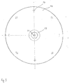
- valve stem 20 is rigidly connected to the two closing body plates 14, 15 by means of a cylindrical connecting element 22. Above the valve stem 20 is located on the top of the upper closure body plate 14, a plate 23 for weighting of the closure body. 2, the valve stem 20 has an axial inner bore 21 which, as shown in FIG. 6, extends to the lower end of the valve stem 20, where an opening 32 is provided to communicate the inner bore 21 with the external environment (FIG. at atmospheric pressure) or an external blower or compressed air generator to connect. As shown in Fig.
- the flow resistance can be suitably set by suitably selecting the diameter of the opening at the lower end of the valve stem, the axial inner bore 21 and the radial bore 24 and the height of the gap 16.
- a plurality of radial bores 24 are shown in the connecting element 22 in FIG. 2, it is preferred according to the invention to prefer only one opening, for example a substantially rectangular circumferential slot, in the connecting element 22, since in this way a particularly simple mechanical construction of the valve 10 can be achieved ,
- the emission control system is preferably operated with a considerable negative pressure, so that above and below the valve 10, a negative pressure prevails, which is less than about 0.1 bar and preferably about 40 to 60 mbar.
- dirt deposits for example soot particles and the like, are preferably deposited on the upwardly facing bevelled ones.
- Store valve seat surfaces 13 Such dirt deposits can also lead to mechanical damage to the valve seat and / or the closure body during continuous operation of the valve, with the undesirable consequence of a leak in the valve.
- dirt deposits on the slanted valve seat surface 13 can be blown away by the scavenging air flowing radially outwardly from the gap 16 when the valve is open.
- the flow velocity of the purging air emerging radially from the intermediate space 16 is essentially determined by the height of the gap or gap 16.
- a bearing block 41 which supports a central drive shaft 40 (see FIG.
- the rotational drive force of the drive shaft 40 is transmitted via two intermeshing gears 42, 43 to the eccentrically coupled to the gear 43 coupling rod 44 which is articulated to the connecting member 45 which is connected to a rocker arm 46, about a pivot axis which is vertically above the rotational center of the drive shaft 40 and the gear 43, pivotally mounted on the bearing block 41.
- the self-weight of the closure body, any weight plates and the valve stem is selected so that the lower end of the valve stem 20 permanently abuts against the respective end of the rocker arm 46.
- the two associated valve stems 20 are operated in opposite directions. For example, if the rocker arm 46 is tilted clockwise, the left valve stem 20 is raised, to open the associated valve, and the right valve stem 20 is lowered to the same extent to lock the associated valve.
- the open position of the two associated with a respective bearing block 41 valves is given by the respective angular position of the coupling rod 44 in a unique way.
- the valves of the exhaust gas purification system can be operated suitably clocked to suitably block and regulate an exhaust gas flow in the exhaust gas purification system 1.
- the coupling rods 44 are offset from each other at equal angular intervals, as described in more detail in EP 1 258 678 A2, the content of which by way of reference is expressly included for disclosure purposes in the present application.
- valve stem 20 is axially displaceably mounted.
- suitable bearing bushes (not shown) are provided on said regions 50, 51.
- valve stem 20 is also rotatably mounted in this bushings about its longitudinal axis, so that valve stem 20 and closure body can rotate together about the longitudinal axis of the valve stem 20.
- a slow rotational movement of the valve stem 20 induced about its longitudinal axis so not always the same areas of the tapered valve seat surface 13 and the outer peripheral edges 18, 19 of the two closure body plates in continuous operation of the valve 10 14. 15 abut each other, but these areas change.
- the longitudinal axis of the valve stem 20 is offset from the center line of the coupling rod 44.
- the connecting member 44 or the abutment region on the upper side of the rocker arm 46 acts off-center on the end plate 30 at the lower end of the valve stem 20.
- Frictional forces which prevail in raising and lowering the valve stem 20 due to the sliding contact between the end plate 30 and the connecting member 45 and the abutment surface on the top of the rocker arm (not shown in FIG. 4) induce a torque which causes rotation of the valve stem 20 Valve stem 20 leads around its longitudinal axis. This torque can be increased by further measures.
- the top of the connecting member 45 and the abutment surface on the top of the rocker arm may be chamfered or curved and the underside of the end plate 30 at the lower end of the valve stem 20 may be bevelled or curved in opposite directions.
- the upper end of the connecting member 45 and on the Top of the rocker arm may be stored a roller 47 or a rolling element.
Landscapes
- Engineering & Computer Science (AREA)
- Environmental & Geological Engineering (AREA)
- Chemical & Material Sciences (AREA)
- General Chemical & Material Sciences (AREA)
- Chemical Kinetics & Catalysis (AREA)
- Biomedical Technology (AREA)
- General Engineering & Computer Science (AREA)
- Analytical Chemistry (AREA)
- Mechanical Engineering (AREA)
- Oil, Petroleum & Natural Gas (AREA)
- Health & Medical Sciences (AREA)
- Lift Valve (AREA)
- Sliding Valves (AREA)
- Filtering Of Dispersed Particles In Gases (AREA)
- Exhaust Gas After Treatment (AREA)
- Control Of Eletrric Generators (AREA)
- Electric Propulsion And Braking For Vehicles (AREA)
Applications Claiming Priority (1)
| Application Number | Priority Date | Filing Date | Title |
|---|---|---|---|
| DE102004040678A DE102004040678B3 (de) | 2004-08-20 | 2004-08-20 | Ventil für thermisch-regenerative Abgasreinigungsanlage und Abgasreinigungsanlage |
Publications (3)
| Publication Number | Publication Date |
|---|---|
| EP1628073A2 true EP1628073A2 (fr) | 2006-02-22 |
| EP1628073A3 EP1628073A3 (fr) | 2006-04-12 |
| EP1628073B1 EP1628073B1 (fr) | 2008-08-06 |
Family
ID=35311532
Family Applications (1)
| Application Number | Title | Priority Date | Filing Date |
|---|---|---|---|
| EP05107632A Expired - Lifetime EP1628073B1 (fr) | 2004-08-20 | 2005-08-19 | Vanne d'une installation de purification de gaz d'échappement et installation de purification de gaz d'échappement |
Country Status (3)
| Country | Link |
|---|---|
| EP (1) | EP1628073B1 (fr) |
| AT (1) | ATE403835T1 (fr) |
| DE (2) | DE102004040678B3 (fr) |
Families Citing this family (1)
| Publication number | Priority date | Publication date | Assignee | Title |
|---|---|---|---|---|
| CN116464972B (zh) * | 2023-04-21 | 2023-09-22 | 江苏大信环境科技有限公司 | 高密封性蓄热式焚烧炉 |
Family Cites Families (8)
| Publication number | Priority date | Publication date | Assignee | Title |
|---|---|---|---|---|
| FR679464A (fr) * | 1928-08-07 | 1930-04-14 | Ig Farbenindustrie Ag | Soupape pour substances poussiéreuses |
| DE526231C (de) * | 1930-01-12 | 1931-06-03 | I G Farbenindustrie Akt Ges | Ventil |
| RU1839701C (ru) * | 1988-01-20 | 1993-12-30 | Ханс Отто Мит (DE) | Клапан с защитным элементом дл уплотнени |
| US5134945A (en) * | 1992-01-06 | 1992-08-04 | Reimlinger Richard G | Regenerative thermal oxidizer with gate manifold system |
| DE19720205B4 (de) * | 1997-05-14 | 2006-05-18 | Johannes Schedler | Anlage zur Reinigung von mit Stickoxiden beladenen Abgasen |
| US6039927A (en) * | 1997-11-04 | 2000-03-21 | Greco; Richard | Valve system for regenerative thermal oxidizers |
| ITMI20010271U1 (it) * | 2001-05-15 | 2002-11-15 | Radaelli Angelo | Valvola a tenuta ermetica per un impianto di titpo termico rigenerativo di depurazione emissioni |
| DE20118418U1 (de) * | 2001-11-14 | 2002-03-21 | Dürr Environmental GmbH, 70435 Stuttgart | Abluftreinigungsvorrichtung |
-
2004
- 2004-08-20 DE DE102004040678A patent/DE102004040678B3/de not_active Expired - Fee Related
-
2005
- 2005-08-19 EP EP05107632A patent/EP1628073B1/fr not_active Expired - Lifetime
- 2005-08-19 DE DE502005004931T patent/DE502005004931D1/de not_active Expired - Fee Related
- 2005-08-19 AT AT05107632T patent/ATE403835T1/de not_active IP Right Cessation
Also Published As
| Publication number | Publication date |
|---|---|
| EP1628073A3 (fr) | 2006-04-12 |
| DE102004040678B3 (de) | 2006-02-02 |
| EP1628073B1 (fr) | 2008-08-06 |
| ATE403835T1 (de) | 2008-08-15 |
| DE502005004931D1 (de) | 2008-09-18 |
Similar Documents
| Publication | Publication Date | Title |
|---|---|---|
| DE3928466C2 (de) | Beschickungsanlage für einen Schachtofen | |
| EP0588185B1 (fr) | Echangeur de chaleur à régénération | |
| DE3544466C2 (de) | Ventilsystem, insbesondere für Abgas-Verbrennungssysteme | |
| DE3342572C2 (fr) | ||
| AT506459A2 (de) | Vorrichtung und verfahren zur reinigung von schadstoffhaltigem abgas | |
| DE102010013664A1 (de) | Schmelzprozess mit durchschiebbarer Verblendung | |
| CH662069A5 (de) | Verfahren zum reinigen von maschinenteilen mit einem geschlossenen hohlraum. | |
| DE3333764A1 (de) | Keramischer rekuperator | |
| EP2531753B1 (fr) | Tiroir rotative motorisé | |
| EP2023070B1 (fr) | Echangeur thermique régénératif, joint radial destiné à l'utilisation pour celui-ci et procédé destiné à la séparation de milieux gazeux dans un échangeur thermique régénératif | |
| EP1628073B1 (fr) | Vanne d'une installation de purification de gaz d'échappement et installation de purification de gaz d'échappement | |
| CH684954A5 (de) | Zahnradpumpe. | |
| DE69412573T2 (de) | Wärmetauscher für Verbrennungsvorrichtung | |
| DE3401792A1 (de) | Vorrichtung zur abstuetzung des in kontinuierlich arbeitenden waermebehandlungsoefen behandelten materials | |
| CH662626A5 (de) | Schieberventilanordnung. | |
| DE102021002658B4 (de) | Holzgaskessel | |
| EP0174970A1 (fr) | Amenagements de puits pour des procedes de transferts de matiere et/ou thermiques entre un gaz et un materiau en vrac. | |
| DE1949471C3 (de) | Klappendichtung fur Schachtofen, insbesondere fur im Hochdruckverfahren betreibbare Hochofen | |
| EP2588829A1 (fr) | Élément de transfert de chaleur pour un échangeur de chaleur, procédé de fabrication d'un élément de transfert de chaleur pour un échangeur de chaleur, échangeur de chaleur et procédé de rééquipement pour un échangeur de chaleur | |
| DE19738678B4 (de) | Regenerativ-Reaktor | |
| DE2406703A1 (de) | Absperrvorrichtung fuer rohrleitungen, insbesondere rohgasleitungen von hochoefen | |
| DE19926405C2 (de) | Verfahren zur thermischen Regeneration des Wärmetauschermaterials einer regenerativen Nachverbrennungsvorrichtung | |
| CH644946A5 (de) | Vorrichtung zur thermischen regenerativbehandlung einer gasstroemung. | |
| DE3245688C2 (fr) | ||
| EP2192209A2 (fr) | Dispositif à nettoyage des composants oxydés ou corrodés en présence d'un mélange gazeux de halogènes |
Legal Events
| Date | Code | Title | Description |
|---|---|---|---|
| PUAI | Public reference made under article 153(3) epc to a published international application that has entered the european phase |
Free format text: ORIGINAL CODE: 0009012 |
|
| AK | Designated contracting states |
Kind code of ref document: A2 Designated state(s): AT BE BG CH CY CZ DE DK EE ES FI FR GB GR HU IE IS IT LI LT LU LV MC NL PL PT RO SE SI SK TR |
|
| AX | Request for extension of the european patent |
Extension state: AL BA HR MK YU |
|
| PUAL | Search report despatched |
Free format text: ORIGINAL CODE: 0009013 |
|
| AK | Designated contracting states |
Kind code of ref document: A3 Designated state(s): AT BE BG CH CY CZ DE DK EE ES FI FR GB GR HU IE IS IT LI LT LU LV MC NL PL PT RO SE SI SK TR |
|
| AX | Request for extension of the european patent |
Extension state: AL BA HR MK YU |
|
| 17P | Request for examination filed |
Effective date: 20061010 |
|
| AKX | Designation fees paid |
Designated state(s): AT BE BG CH CY CZ DE DK EE ES FI FR GB GR HU IE IS IT LI LT LU LV MC NL PL PT RO SE SI SK TR |
|
| GRAP | Despatch of communication of intention to grant a patent |
Free format text: ORIGINAL CODE: EPIDOSNIGR1 |
|
| GRAS | Grant fee paid |
Free format text: ORIGINAL CODE: EPIDOSNIGR3 |
|
| GRAA | (expected) grant |
Free format text: ORIGINAL CODE: 0009210 |
|
| AK | Designated contracting states |
Kind code of ref document: B1 Designated state(s): AT BE BG CH CY CZ DE DK EE ES FI FR GB GR HU IE IS IT LI LT LU LV MC NL PL PT RO SE SI SK TR |
|
| REG | Reference to a national code |
Ref country code: GB Ref legal event code: FG4D Free format text: NOT ENGLISH |
|
| REG | Reference to a national code |
Ref country code: CH Ref legal event code: EP |
|
| REG | Reference to a national code |
Ref country code: IE Ref legal event code: FG4D Free format text: LANGUAGE OF EP DOCUMENT: GERMAN |
|
| REF | Corresponds to: |
Ref document number: 502005004931 Country of ref document: DE Date of ref document: 20080918 Kind code of ref document: P |
|
| PG25 | Lapsed in a contracting state [announced via postgrant information from national office to epo] |
Ref country code: LT Free format text: LAPSE BECAUSE OF FAILURE TO SUBMIT A TRANSLATION OF THE DESCRIPTION OR TO PAY THE FEE WITHIN THE PRESCRIBED TIME-LIMIT Effective date: 20080806 Ref country code: IS Free format text: LAPSE BECAUSE OF FAILURE TO SUBMIT A TRANSLATION OF THE DESCRIPTION OR TO PAY THE FEE WITHIN THE PRESCRIBED TIME-LIMIT Effective date: 20081206 Ref country code: NL Free format text: LAPSE BECAUSE OF FAILURE TO SUBMIT A TRANSLATION OF THE DESCRIPTION OR TO PAY THE FEE WITHIN THE PRESCRIBED TIME-LIMIT Effective date: 20080806 |
|
| PG25 | Lapsed in a contracting state [announced via postgrant information from national office to epo] |
Ref country code: ES Free format text: LAPSE BECAUSE OF FAILURE TO SUBMIT A TRANSLATION OF THE DESCRIPTION OR TO PAY THE FEE WITHIN THE PRESCRIBED TIME-LIMIT Effective date: 20081117 Ref country code: SI Free format text: LAPSE BECAUSE OF FAILURE TO SUBMIT A TRANSLATION OF THE DESCRIPTION OR TO PAY THE FEE WITHIN THE PRESCRIBED TIME-LIMIT Effective date: 20080806 Ref country code: FI Free format text: LAPSE BECAUSE OF FAILURE TO SUBMIT A TRANSLATION OF THE DESCRIPTION OR TO PAY THE FEE WITHIN THE PRESCRIBED TIME-LIMIT Effective date: 20080806 Ref country code: LV Free format text: LAPSE BECAUSE OF FAILURE TO SUBMIT A TRANSLATION OF THE DESCRIPTION OR TO PAY THE FEE WITHIN THE PRESCRIBED TIME-LIMIT Effective date: 20080806 |
|
| REG | Reference to a national code |
Ref country code: IE Ref legal event code: FD4D |
|
| PG25 | Lapsed in a contracting state [announced via postgrant information from national office to epo] |
Ref country code: MC Free format text: LAPSE BECAUSE OF NON-PAYMENT OF DUE FEES Effective date: 20080831 |
|
| PG25 | Lapsed in a contracting state [announced via postgrant information from national office to epo] |
Ref country code: IE Free format text: LAPSE BECAUSE OF FAILURE TO SUBMIT A TRANSLATION OF THE DESCRIPTION OR TO PAY THE FEE WITHIN THE PRESCRIBED TIME-LIMIT Effective date: 20080806 Ref country code: DK Free format text: LAPSE BECAUSE OF FAILURE TO SUBMIT A TRANSLATION OF THE DESCRIPTION OR TO PAY THE FEE WITHIN THE PRESCRIBED TIME-LIMIT Effective date: 20080806 Ref country code: BG Free format text: LAPSE BECAUSE OF FAILURE TO SUBMIT A TRANSLATION OF THE DESCRIPTION OR TO PAY THE FEE WITHIN THE PRESCRIBED TIME-LIMIT Effective date: 20081106 |
|
| PG25 | Lapsed in a contracting state [announced via postgrant information from national office to epo] |
Ref country code: CZ Free format text: LAPSE BECAUSE OF FAILURE TO SUBMIT A TRANSLATION OF THE DESCRIPTION OR TO PAY THE FEE WITHIN THE PRESCRIBED TIME-LIMIT Effective date: 20080806 Ref country code: PT Free format text: LAPSE BECAUSE OF FAILURE TO SUBMIT A TRANSLATION OF THE DESCRIPTION OR TO PAY THE FEE WITHIN THE PRESCRIBED TIME-LIMIT Effective date: 20090106 Ref country code: SK Free format text: LAPSE BECAUSE OF FAILURE TO SUBMIT A TRANSLATION OF THE DESCRIPTION OR TO PAY THE FEE WITHIN THE PRESCRIBED TIME-LIMIT Effective date: 20080806 Ref country code: RO Free format text: LAPSE BECAUSE OF FAILURE TO SUBMIT A TRANSLATION OF THE DESCRIPTION OR TO PAY THE FEE WITHIN THE PRESCRIBED TIME-LIMIT Effective date: 20080806 |
|
| PLBE | No opposition filed within time limit |
Free format text: ORIGINAL CODE: 0009261 |
|
| STAA | Information on the status of an ep patent application or granted ep patent |
Free format text: STATUS: NO OPPOSITION FILED WITHIN TIME LIMIT |
|
| 26N | No opposition filed |
Effective date: 20090507 |
|
| REG | Reference to a national code |
Ref country code: FR Ref legal event code: ST Effective date: 20090630 |
|
| PG25 | Lapsed in a contracting state [announced via postgrant information from national office to epo] |
Ref country code: EE Free format text: LAPSE BECAUSE OF FAILURE TO SUBMIT A TRANSLATION OF THE DESCRIPTION OR TO PAY THE FEE WITHIN THE PRESCRIBED TIME-LIMIT Effective date: 20080806 Ref country code: BE Free format text: LAPSE BECAUSE OF NON-PAYMENT OF DUE FEES Effective date: 20080831 |
|
| PG25 | Lapsed in a contracting state [announced via postgrant information from national office to epo] |
Ref country code: IT Free format text: LAPSE BECAUSE OF FAILURE TO SUBMIT A TRANSLATION OF THE DESCRIPTION OR TO PAY THE FEE WITHIN THE PRESCRIBED TIME-LIMIT Effective date: 20080806 Ref country code: DE Free format text: LAPSE BECAUSE OF NON-PAYMENT OF DUE FEES Effective date: 20090303 |
|
| PG25 | Lapsed in a contracting state [announced via postgrant information from national office to epo] |
Ref country code: FR Free format text: LAPSE BECAUSE OF NON-PAYMENT OF DUE FEES Effective date: 20080901 Ref country code: AT Free format text: LAPSE BECAUSE OF NON-PAYMENT OF DUE FEES Effective date: 20080819 |
|
| PG25 | Lapsed in a contracting state [announced via postgrant information from national office to epo] |
Ref country code: SE Free format text: LAPSE BECAUSE OF FAILURE TO SUBMIT A TRANSLATION OF THE DESCRIPTION OR TO PAY THE FEE WITHIN THE PRESCRIBED TIME-LIMIT Effective date: 20081106 |
|
| REG | Reference to a national code |
Ref country code: CH Ref legal event code: PL |
|
| GBPC | Gb: european patent ceased through non-payment of renewal fee |
Effective date: 20090819 |
|
| PG25 | Lapsed in a contracting state [announced via postgrant information from national office to epo] |
Ref country code: LI Free format text: LAPSE BECAUSE OF NON-PAYMENT OF DUE FEES Effective date: 20090831 Ref country code: CH Free format text: LAPSE BECAUSE OF NON-PAYMENT OF DUE FEES Effective date: 20090831 |
|
| PG25 | Lapsed in a contracting state [announced via postgrant information from national office to epo] |
Ref country code: PL Free format text: LAPSE BECAUSE OF FAILURE TO SUBMIT A TRANSLATION OF THE DESCRIPTION OR TO PAY THE FEE WITHIN THE PRESCRIBED TIME-LIMIT Effective date: 20080806 |
|
| PG25 | Lapsed in a contracting state [announced via postgrant information from national office to epo] |
Ref country code: CY Free format text: LAPSE BECAUSE OF FAILURE TO SUBMIT A TRANSLATION OF THE DESCRIPTION OR TO PAY THE FEE WITHIN THE PRESCRIBED TIME-LIMIT Effective date: 20080806 Ref country code: HU Free format text: LAPSE BECAUSE OF FAILURE TO SUBMIT A TRANSLATION OF THE DESCRIPTION OR TO PAY THE FEE WITHIN THE PRESCRIBED TIME-LIMIT Effective date: 20090207 Ref country code: LU Free format text: LAPSE BECAUSE OF NON-PAYMENT OF DUE FEES Effective date: 20080819 |
|
| PG25 | Lapsed in a contracting state [announced via postgrant information from national office to epo] |
Ref country code: TR Free format text: LAPSE BECAUSE OF FAILURE TO SUBMIT A TRANSLATION OF THE DESCRIPTION OR TO PAY THE FEE WITHIN THE PRESCRIBED TIME-LIMIT Effective date: 20080806 |
|
| PG25 | Lapsed in a contracting state [announced via postgrant information from national office to epo] |
Ref country code: GB Free format text: LAPSE BECAUSE OF NON-PAYMENT OF DUE FEES Effective date: 20090819 |
|
| PG25 | Lapsed in a contracting state [announced via postgrant information from national office to epo] |
Ref country code: GR Free format text: LAPSE BECAUSE OF NON-PAYMENT OF DUE FEES Effective date: 20080831 |