EP1628086A2 - Klimaanlage - Google Patents
Klimaanlage Download PDFInfo
- Publication number
- EP1628086A2 EP1628086A2 EP05107298A EP05107298A EP1628086A2 EP 1628086 A2 EP1628086 A2 EP 1628086A2 EP 05107298 A EP05107298 A EP 05107298A EP 05107298 A EP05107298 A EP 05107298A EP 1628086 A2 EP1628086 A2 EP 1628086A2
- Authority
- EP
- European Patent Office
- Prior art keywords
- refrigerant
- compressor
- cooling water
- bypass
- valve
- Prior art date
- Legal status (The legal status is an assumption and is not a legal conclusion. Google has not performed a legal analysis and makes no representation as to the accuracy of the status listed.)
- Granted
Links
Images


Classifications
-
- F—MECHANICAL ENGINEERING; LIGHTING; HEATING; WEAPONS; BLASTING
- F24—HEATING; RANGES; VENTILATING
- F24F—AIR-CONDITIONING; AIR-HUMIDIFICATION; VENTILATION; USE OF AIR CURRENTS FOR SCREENING
- F24F11/00—Control or safety arrangements
- F24F11/89—Arrangement or mounting of control or safety devices
-
- F—MECHANICAL ENGINEERING; LIGHTING; HEATING; WEAPONS; BLASTING
- F25—REFRIGERATION OR COOLING; COMBINED HEATING AND REFRIGERATION SYSTEMS; HEAT PUMP SYSTEMS; MANUFACTURE OR STORAGE OF ICE; LIQUEFACTION SOLIDIFICATION OF GASES
- F25B—REFRIGERATION MACHINES, PLANTS OR SYSTEMS; COMBINED HEATING AND REFRIGERATION SYSTEMS; HEAT PUMP SYSTEMS
- F25B27/00—Machines, plants or systems, using particular sources of energy
- F25B27/02—Machines, plants or systems, using particular sources of energy using waste heat, e.g. from internal-combustion engines
-
- F—MECHANICAL ENGINEERING; LIGHTING; HEATING; WEAPONS; BLASTING
- F25—REFRIGERATION OR COOLING; COMBINED HEATING AND REFRIGERATION SYSTEMS; HEAT PUMP SYSTEMS; MANUFACTURE OR STORAGE OF ICE; LIQUEFACTION SOLIDIFICATION OF GASES
- F25B—REFRIGERATION MACHINES, PLANTS OR SYSTEMS; COMBINED HEATING AND REFRIGERATION SYSTEMS; HEAT PUMP SYSTEMS
- F25B1/00—Compression machines, plants or systems with non-reversible cycle
-
- F—MECHANICAL ENGINEERING; LIGHTING; HEATING; WEAPONS; BLASTING
- F25—REFRIGERATION OR COOLING; COMBINED HEATING AND REFRIGERATION SYSTEMS; HEAT PUMP SYSTEMS; MANUFACTURE OR STORAGE OF ICE; LIQUEFACTION SOLIDIFICATION OF GASES
- F25B—REFRIGERATION MACHINES, PLANTS OR SYSTEMS; COMBINED HEATING AND REFRIGERATION SYSTEMS; HEAT PUMP SYSTEMS
- F25B13/00—Compression machines, plants or systems, with reversible cycle
-
- F—MECHANICAL ENGINEERING; LIGHTING; HEATING; WEAPONS; BLASTING
- F25—REFRIGERATION OR COOLING; COMBINED HEATING AND REFRIGERATION SYSTEMS; HEAT PUMP SYSTEMS; MANUFACTURE OR STORAGE OF ICE; LIQUEFACTION SOLIDIFICATION OF GASES
- F25B—REFRIGERATION MACHINES, PLANTS OR SYSTEMS; COMBINED HEATING AND REFRIGERATION SYSTEMS; HEAT PUMP SYSTEMS
- F25B41/00—Fluid-circulation arrangements
- F25B41/20—Disposition of valves, e.g. of on-off valves or flow control valves
-
- F—MECHANICAL ENGINEERING; LIGHTING; HEATING; WEAPONS; BLASTING
- F24—HEATING; RANGES; VENTILATING
- F24F—AIR-CONDITIONING; AIR-HUMIDIFICATION; VENTILATION; USE OF AIR CURRENTS FOR SCREENING
- F24F2110/00—Control inputs relating to air properties
- F24F2110/10—Temperature
- F24F2110/12—Temperature of the outside air
-
- F—MECHANICAL ENGINEERING; LIGHTING; HEATING; WEAPONS; BLASTING
- F24—HEATING; RANGES; VENTILATING
- F24F—AIR-CONDITIONING; AIR-HUMIDIFICATION; VENTILATION; USE OF AIR CURRENTS FOR SCREENING
- F24F2140/00—Control inputs relating to system states
- F24F2140/10—Pressure
- F24F2140/12—Heat-exchange fluid pressure
-
- F—MECHANICAL ENGINEERING; LIGHTING; HEATING; WEAPONS; BLASTING
- F25—REFRIGERATION OR COOLING; COMBINED HEATING AND REFRIGERATION SYSTEMS; HEAT PUMP SYSTEMS; MANUFACTURE OR STORAGE OF ICE; LIQUEFACTION SOLIDIFICATION OF GASES
- F25B—REFRIGERATION MACHINES, PLANTS OR SYSTEMS; COMBINED HEATING AND REFRIGERATION SYSTEMS; HEAT PUMP SYSTEMS
- F25B2313/00—Compression machines, plants or systems with reversible cycle not otherwise provided for
- F25B2313/021—Indoor unit or outdoor unit with auxiliary heat exchanger not forming part of the indoor or outdoor unit
- F25B2313/0213—Indoor unit or outdoor unit with auxiliary heat exchanger not forming part of the indoor or outdoor unit the auxiliary heat exchanger being only used during heating
-
- F—MECHANICAL ENGINEERING; LIGHTING; HEATING; WEAPONS; BLASTING
- F25—REFRIGERATION OR COOLING; COMBINED HEATING AND REFRIGERATION SYSTEMS; HEAT PUMP SYSTEMS; MANUFACTURE OR STORAGE OF ICE; LIQUEFACTION SOLIDIFICATION OF GASES
- F25B—REFRIGERATION MACHINES, PLANTS OR SYSTEMS; COMBINED HEATING AND REFRIGERATION SYSTEMS; HEAT PUMP SYSTEMS
- F25B2313/00—Compression machines, plants or systems with reversible cycle not otherwise provided for
- F25B2313/025—Compression machines, plants or systems with reversible cycle not otherwise provided for using multiple outdoor units
- F25B2313/0252—Compression machines, plants or systems with reversible cycle not otherwise provided for using multiple outdoor units with bypasses
- F25B2313/02523—Compression machines, plants or systems with reversible cycle not otherwise provided for using multiple outdoor units with bypasses during heating
-
- F—MECHANICAL ENGINEERING; LIGHTING; HEATING; WEAPONS; BLASTING
- F25—REFRIGERATION OR COOLING; COMBINED HEATING AND REFRIGERATION SYSTEMS; HEAT PUMP SYSTEMS; MANUFACTURE OR STORAGE OF ICE; LIQUEFACTION SOLIDIFICATION OF GASES
- F25B—REFRIGERATION MACHINES, PLANTS OR SYSTEMS; COMBINED HEATING AND REFRIGERATION SYSTEMS; HEAT PUMP SYSTEMS
- F25B2313/00—Compression machines, plants or systems with reversible cycle not otherwise provided for
- F25B2313/027—Compression machines, plants or systems with reversible cycle not otherwise provided for characterised by the reversing means
- F25B2313/02741—Compression machines, plants or systems with reversible cycle not otherwise provided for characterised by the reversing means using one four-way valve
-
- F—MECHANICAL ENGINEERING; LIGHTING; HEATING; WEAPONS; BLASTING
- F25—REFRIGERATION OR COOLING; COMBINED HEATING AND REFRIGERATION SYSTEMS; HEAT PUMP SYSTEMS; MANUFACTURE OR STORAGE OF ICE; LIQUEFACTION SOLIDIFICATION OF GASES
- F25B—REFRIGERATION MACHINES, PLANTS OR SYSTEMS; COMBINED HEATING AND REFRIGERATION SYSTEMS; HEAT PUMP SYSTEMS
- F25B2500/00—Problems to be solved
- F25B2500/31—Low ambient temperatures
-
- F—MECHANICAL ENGINEERING; LIGHTING; HEATING; WEAPONS; BLASTING
- F25—REFRIGERATION OR COOLING; COMBINED HEATING AND REFRIGERATION SYSTEMS; HEAT PUMP SYSTEMS; MANUFACTURE OR STORAGE OF ICE; LIQUEFACTION SOLIDIFICATION OF GASES
- F25B—REFRIGERATION MACHINES, PLANTS OR SYSTEMS; COMBINED HEATING AND REFRIGERATION SYSTEMS; HEAT PUMP SYSTEMS
- F25B2700/00—Sensing or detecting of parameters; Sensors therefor
- F25B2700/19—Pressures
- F25B2700/193—Pressures of the compressor
- F25B2700/1931—Discharge pressures
-
- F—MECHANICAL ENGINEERING; LIGHTING; HEATING; WEAPONS; BLASTING
- F25—REFRIGERATION OR COOLING; COMBINED HEATING AND REFRIGERATION SYSTEMS; HEAT PUMP SYSTEMS; MANUFACTURE OR STORAGE OF ICE; LIQUEFACTION SOLIDIFICATION OF GASES
- F25B—REFRIGERATION MACHINES, PLANTS OR SYSTEMS; COMBINED HEATING AND REFRIGERATION SYSTEMS; HEAT PUMP SYSTEMS
- F25B2700/00—Sensing or detecting of parameters; Sensors therefor
- F25B2700/19—Pressures
- F25B2700/193—Pressures of the compressor
- F25B2700/1933—Suction pressures
-
- F—MECHANICAL ENGINEERING; LIGHTING; HEATING; WEAPONS; BLASTING
- F25—REFRIGERATION OR COOLING; COMBINED HEATING AND REFRIGERATION SYSTEMS; HEAT PUMP SYSTEMS; MANUFACTURE OR STORAGE OF ICE; LIQUEFACTION SOLIDIFICATION OF GASES
- F25B—REFRIGERATION MACHINES, PLANTS OR SYSTEMS; COMBINED HEATING AND REFRIGERATION SYSTEMS; HEAT PUMP SYSTEMS
- F25B2700/00—Sensing or detecting of parameters; Sensors therefor
- F25B2700/21—Temperatures
- F25B2700/2104—Temperatures of an indoor room or compartment
-
- F—MECHANICAL ENGINEERING; LIGHTING; HEATING; WEAPONS; BLASTING
- F25—REFRIGERATION OR COOLING; COMBINED HEATING AND REFRIGERATION SYSTEMS; HEAT PUMP SYSTEMS; MANUFACTURE OR STORAGE OF ICE; LIQUEFACTION SOLIDIFICATION OF GASES
- F25B—REFRIGERATION MACHINES, PLANTS OR SYSTEMS; COMBINED HEATING AND REFRIGERATION SYSTEMS; HEAT PUMP SYSTEMS
- F25B2700/00—Sensing or detecting of parameters; Sensors therefor
- F25B2700/21—Temperatures
- F25B2700/2106—Temperatures of fresh outdoor air
-
- Y—GENERAL TAGGING OF NEW TECHNOLOGICAL DEVELOPMENTS; GENERAL TAGGING OF CROSS-SECTIONAL TECHNOLOGIES SPANNING OVER SEVERAL SECTIONS OF THE IPC; TECHNICAL SUBJECTS COVERED BY FORMER USPC CROSS-REFERENCE ART COLLECTIONS [XRACs] AND DIGESTS
- Y02—TECHNOLOGIES OR APPLICATIONS FOR MITIGATION OR ADAPTATION AGAINST CLIMATE CHANGE
- Y02A—TECHNOLOGIES FOR ADAPTATION TO CLIMATE CHANGE
- Y02A30/00—Adapting or protecting infrastructure or their operation
- Y02A30/27—Relating to heating, ventilation or air conditioning [HVAC] technologies
- Y02A30/274—Relating to heating, ventilation or air conditioning [HVAC] technologies using waste energy, e.g. from internal combustion engine
Definitions
- the present invention relates to an air conditioner for heating or cooling a space including a compressor, an indoor heat exchanger located in said space and an outdoor heat exchanger connected together in a refrigeration circuit, the air conditioner further comprising a control unit for controlling the flow of refrigerant through said refrigeration circuit.
- An air conditioning system generally employs a refrigeration cycle to control air temperature and humidity in residential and office buildings.
- the air refrigeration cycle comprises the steps of compression, condensation, expansion and evaporation of refrigerant in the system, such that heating is achieved by heat radiation due to the condensation process, and cooling is achieved by heat absorption due to the evaporation process.
- GHP gas engine-driven heat pump
- EHP electric motor-driven heat pump
- a conventional air conditioning system has the following problems when a heating operation is performed at a low outdoor temperature. Firstly, the pressure of the refrigerant discharged from the compressor (i.e., a high pressure part) and the pressure of the refrigerant introduced into the compressor (i.e., a low pressure part) are both low even when the gas engine is rotated at a maximum speed. This means that only a small amount of the refrigerant is circulated and so the heating effect of the air conditioning system is lowered.
- the heating effect depends on the adjustment of an outdoor expansion valve. Therefore, the heating effect is limited when the outdoor temperature is low.
- the heating effect may be adjusted by controlling a cooling water valve to adjust cooling water heated by waste heat of the gas engine. The allowable adjustment is limited.
- the present invention seeks to provide an air conditioning system which overcomes or substantially alleviates the problems discussed above.
- An air conditioning system is characterised by a bypass conduit to divert refrigerant that has flowed through the indoor heat exchanger during a heating operation back to the compressor when an outdoor temperature sensed by an outdoor temperature sensor is at or below a predetermined outdoor reference temperature and, when a refrigerant pressure sensed by a low pressure sensor is at or below a predetermined pressure.
- the air conditioner comprises a bypass valve disposed in the bypass conduit, the control unit being operable to open and close the valve to permit or prevent the flow of refrigerant through the bypass conduit.
- the air conditioner comprises an expansion valve, the bypass conduit being positioned such that refrigerant that has passed through the indoor heat exchanger is diverted through the bypass conduit prior to passing through the expansion valve.
- the bypass valve comprises high and low flow capacity valve members, and the control unit is operable to open the high flow capacity valve prior to opening the low flow capacity valve.
- the present invention also provides a method of controlling an air conditioner for heating or cooling a space including a compressor, an indoor heat exchanger located in said space and an outdoor heat exchanger connected together in a refrigeration circuit, the air conditioner further comprising a control unit for controlling the flow of refrigerant through said refrigeration circuit.
- the method according to the present invention is characterised by the step of diverting refrigerant that has flowed through the indoor heat exchanger during a heating operation back to the compressor via a bypass conduit, when an outdoor temperature sensed by an outdoor temperature sensor is at or below a predetermined outdoor reference temperature and, when a refrigerant pressure sensed by a low pressure sensor is at or below a predetermined pressure.
- the compressor drive comprises a gas heat pump.
- FIG. 1 an air conditioning system including a compressor 6, an outdoor heat exchanging unit 2, a refrigerant expansion unit 7, and an indoor heat exchanging unit 1, which are connected in sequence by a refrigerant pipe in sequence to form a closed loop.
- the refrigerant pipe connected between the compressor 6 outlet and the refrigerant expansion unit 7 is a high pressure pipe to guide high pressure refrigerant discharged from the compressor 6.
- the refrigerant pipe connected between the refrigerant expansion unit 7 and the compressor 6 inlet is a low pressure pipe to guide low pressure refrigerant expanded by the refrigerant expansion unit 7.
- the low-pressure pipe and the high-pressure pipe are connected to cross each other by a four-way directional valve 10.
- the four-way directional valve 10 switches the refrigerant flow direction such that the air conditioning system can selectively perform cooling and heating operations.
- the refrigerant flows along a path shown by broken line arrows in Figure 1 through the compressor 6, the four-way directional valve 10, the indoor heat exchanging unit 1, the refrigerant expansion unit 7, the outdoor heat exchanging unit 2, the four-way directional valve 10 and the compressor 6, in sequence. Therefore, during a heating operation the high pressure section of refrigerant pipe connects the compressor 6 outlet, the four-way directional valve 10, the indoor heat exchanging unit 1 and the refrigerant expansion unit 7. Hence, the low pressure section of the refrigerant pipe connects the refrigerant expansion unit 7, the outdoor heat exchanging unit 2, the four-way directional valve 10 and the compressor 6 inlet.
- the refrigerant flows along the path shown by the solid line arrows through the compressor 6, the four-way directional valve 10, the outdoor heat exchanging unit 2, the refrigerant expansion unit 7, the indoor heat exchanging unit 1, the four-way directional valve 10 and the compressor 6 in sequence.
- the high pressure portion of the refrigerant pipe connects the compressor 6 outlet, the four-way directional valve 10, the outdoor heat exchanging unit 2 and the refrigerant expansion unit 7 and the low pressure portion of the refrigerant pipe connects the refrigerant expansion unit 7, the indoor heat exchanging unit 1, the four-way directional valve 10 and the compressor 6 inlet.
- An oil separator 8 is located along the high-pressure pipe between the compressor 6 outlet and the four-way directional valve 10. Oil contained in the refrigerant discharged from the compressor 6 is filtered by the oil separator 8 and the filtrated refrigerant is returned to the compressor 6. The oil lubricates while the compressor 6 operates.
- the outdoor heat exchanging unit 2 includes an outdoor heat exchanger 3 to circulate the refrigerant, a cooling water heat radiator 4 to circulate cooling water for a compressor driver 12, and a fan 5 to blow air across the outdoor heat exchanger 3 and the cooling water heat radiator 4.
- the indoor heat-exchanging unit 1 is located in a space to be cooled or heated, such that heat is exchanged with air contained in the space, henceforth cooling or heating the space.
- An accumulator 9 is located along the low pressure pipe at the compressor 6 inlet.
- the accumulator 9 prevents liquid refrigerant from flowing into the compressor 6.
- the refrigerant expansion unit 7 comprises an indoor expansion valve 7a provided in the indoor heat exchanging unit 7, and an outdoor expansion valve 7b provided adjacent to the outdoor heat exchanging unit 2.
- the indoor expansion valve 7a expands refrigerant flowing from the outdoor heat-exchanging unit 2 towards the indoor heat-exchanging unit 1 during a cooling operation.
- the outdoor expansion valve 7a expands refrigerant flowing from the indoor heat-exchanging unit 1 to the outdoor heat-exchanging unit 2 during a heating operation.
- the air conditioning system employs a gas engine-driven heat pump (GHP) as the compressor driver 12 to drive the compressor 6.
- GHP uses a gas engine driven with gas. Waste heat generated by the gas engine during operation of the compressor driver 12, is transferred to the cooling water circulating along a cooling water pipe.
- the air conditioning system also comprises a cooling water circulating system to remove or exploit waste heat generated by the gas engine when the compressor driver 12 is operated.
- the cooling water circulating system includes the cooling water pipe forming a closed loop, and a cooling water pump 19 to induce the cooling water to flow.
- the cooling water flowing along the cooling water pipe by the cooling water pump 19 absorbs waste heat generated by the compressor driver 12 therein, cooling the compressor driver 12 and heating the cooling water.
- the heated cooling water is controlled by a thermostat 14 such that it returns to the compressor driver 12 or flows towards a cooling water valve 15 dependent on whether the water temperature exceeding a predetermined temperature. If the cooling water exceeds the predetermined temperature it flows to the cooling water valve 15.
- the cooling water valve 15 is opened and closed by a controller 28 allowing the cooling water to selectively flow towards either a refrigerant heating part 11 or the outdoor heat exchanging unit 2.
- a circulation path of the cooling water flowing towards the outdoor heat exchanging unit 2 will be called an outdoor heat exchanging circulation path and the circulation path of the cooling water flowing towards the refrigerant heating part 11 will be called a refrigerant heating circulation path.
- the controller 28 controls the cooling water valve 15 such that the cooling water flows from the thermostat 14 to the refrigerant heating part 11 along the refrigerant heating circulation path during the heating operation.
- the controller 28 also controls the cooling water valve 15 such that the cooling water flows from the thermostat 14 to the cooling water heat radiator 4 of the outdoor heat exchanging unit 2 along the outdoor heat exchanging circulation path during the cooling operation.
- the air conditioning system further includes a cooling water tank 16, a discharging gas heat exchanging unit 17, a discharging muffler 18, an outdoor temperature sensor 25, a high pressure sensor 27, a low pressure sensor 26, a bypass pipe 29, a bypass valve 30, and the controller 28.
- the outdoor temperature sensor 25 is located externally from the internal space such that it can sense the external temperature, and transmit the information to the controller 28.
- the high pressure sensor 27 is installed along the high pressure pipe adjacent to the compressor 6 outlet and senses the pressure of the refrigerant flowing in the high pressure pipe so that it can transmit information regarding the sensed pressure to the controller 28.
- the high pressure sensor 27 is installed between the oil separator 8 and the four-way directional valve 10.
- the low pressure sensor 26 is installed between the compressor 6 and the accumulator 9 and senses the pressure of the refrigerant flowing in the low pressure pipe, so that it can transmit information regarding the sensed pressure to the controller 28.
- the low pressure sensor 26 is installed between the compressor 6 and the accumulator 9.
- the bypass pipe 29 connects the refrigerant pipe disposed between the outdoor heat exchanging unit 2 and the indoor heat exchanging unit 1 with the refrigerant pipe disposed adjacent to the compressor 6.
- the bypass pipe 29 has a first end connected to the refrigerant pipe disposed between the outdoor expansion valve 7b adjacent to the outdoor heat exchanging unit 2 and the indoor expansion valve 7a of the indoor heat exchanging unit 1 and a second end connected to the refrigerant pipe disposed between the compressor 6 and the accumulator 9.
- the bypass valve 30 is located on the bypass pipe 29 and opens/closes the bypass pipe 29 according to the control of the controller 28.
- the bypass valve 30 includes a first bypass valve and a second bypass valve wherein the first bypass valve has a larger capacity compared to the second bypass valve.
- the controller 28 first opens the first bypass valve and then opens the second bypass valve. In a case where the bypass valve 30 is closed, the controller 28 first closes the second bypass valves, and then closes the first bypass valve.
- the bypass valve 30 also includes at least one solenoid valve and an electronic expansion valve (EEV).
- EEV electronic expansion valve
- the solenoid valve may be used as the first bypass valve
- the electronic expansion valve may be used as the second bypass valve.
- two solenoid valves having different capacities from each other may be provided as the first and second bypass valves or the bypass valve 30 may include a single solenoid valve or a single electronic expansion valve.
- the controller 28 opens the bypass valve under a condition in which the temperature sensed by the outdoor temperature sensor 25 is below a predetermined reference temperature. Therein, some of the high pressure refrigerant flowing from the indoor heat exchanging unit 1 to the outdoor heat exchanging unit 2 is bypassed through the bypass pipe 29 and introduced into the compressor 6.
- the compression rate of the compressor 6 is increased, such that the amount of refrigerant circulating in the air conditioning system is increased.
- the heating effect of the air conditioning system is therefore enhanced.
- the controller 28 closes the bypass valve 30 when the pressure sensed by the high pressure sensor 27 exceeds a predetermined pressure.
- the air conditioning system performs a general heating operation as described above.
- the outdoor temperature sensor 25 senses the outdoor temperature, and transmits the information about the sensed outdoor temperature to the controller 28.
- the controller 28 determines whether the sensed outdoor temperature is equal to or below a predetermined reference temperature dependent on the information transmitted by the outdoor temperature sensor 25.
- the controller 28 determines whether the pressure P L sensed by the low pressure sensor 26 is equal to or below a predetermined target low pressure at operation S12.
- the controller 28 opens the bypass valve 30 at operation S13. Therefore, a proportion of the high pressure refrigerant flowing from the indoor heat exchanging unit 1 to the outdoor heat exchanging unit 2 is bypassed through the bypass pipe 29 and introduced into the compressor 6 inlet.
- FIG 4 is a graph showing that the pressure P L sensed by the low pressure sensor 26 and the pressure P H sensed by the high pressure sensor 27 are changed depending on the amount of the refrigerant bypassed through the bypass pipe 29.
- graph B shows a relation between the amount of the refrigerant and the pressure P L sensed by the low pressure sensor 26
- graph A shows a relation between the amount of the refrigerant and the pressure P H sensed by the high pressure sensor 27.
- the amount of the refrigerant is adjustable by the bypass valve 30.
- the controller 28 determines whether the pressure P H sensed by the high pressure sensor 27 is above a predetermined target high pressure. When this occurs, the controller 28 closes the bypass valve 30 at operation S15. Thus, the general heating operation is performed again.
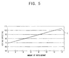
- Figure 5 is a graph showing a relation between the control of the bypass valve 30 and the improvement in the heating effect. As shown in Figure 5, the heating effect is improved when the bypass pipe 30 is opened, that is, when the amount of the refrigerant bypassed through the bypass pipe 30 is increased as compared with when the bypass valve 30 is closed, that is, when the amount of the refrigerant bypassed through the bypass pipe 29 is 0 (refer to graph C).
- bypass pipe 29 and the bypass valve 30 are controlled by the controller 28 and used to improve the heating effect.
- the bypass pipe 29 and the bypass valve 30 may be used for various objects.
- the bypass pipe and the bypass valve may be used to protect the system and the compressor from heat exchanging efficiency deterioration due to the rapid change of an indoor or outdoor load and strange conditions.
Landscapes
- Engineering & Computer Science (AREA)
- Mechanical Engineering (AREA)
- General Engineering & Computer Science (AREA)
- Physics & Mathematics (AREA)
- Thermal Sciences (AREA)
- Chemical & Material Sciences (AREA)
- Combustion & Propulsion (AREA)
- Air Conditioning Control Device (AREA)
- Compression-Type Refrigeration Machines With Reversible Cycles (AREA)
Applications Claiming Priority (1)
| Application Number | Priority Date | Filing Date | Title |
|---|---|---|---|
| KR1020040063180A KR100586989B1 (ko) | 2004-08-11 | 2004-08-11 | 냉난방 공조시스템 및 그 제어방법 |
Publications (3)
| Publication Number | Publication Date |
|---|---|
| EP1628086A2 true EP1628086A2 (de) | 2006-02-22 |
| EP1628086A3 EP1628086A3 (de) | 2007-12-26 |
| EP1628086B1 EP1628086B1 (de) | 2015-04-01 |
Family
ID=36076731
Family Applications (1)
| Application Number | Title | Priority Date | Filing Date |
|---|---|---|---|
| EP05107298.1A Expired - Lifetime EP1628086B1 (de) | 2004-08-11 | 2005-08-08 | Klimaanlage |
Country Status (4)
| Country | Link |
|---|---|
| US (1) | US7377119B2 (de) |
| EP (1) | EP1628086B1 (de) |
| KR (1) | KR100586989B1 (de) |
| CN (1) | CN100339656C (de) |
Cited By (2)
| Publication number | Priority date | Publication date | Assignee | Title |
|---|---|---|---|---|
| EP2781858A1 (de) * | 2013-03-20 | 2014-09-24 | Vaillant GmbH | Wärmepumpe mit mindestens zwei Wärmequellen |
| WO2021137408A1 (en) * | 2019-12-30 | 2021-07-08 | Lg Electronics Inc. | Air conditioning apparatus |
Families Citing this family (17)
| Publication number | Priority date | Publication date | Assignee | Title |
|---|---|---|---|---|
| US7918655B2 (en) * | 2004-04-30 | 2011-04-05 | Computer Process Controls, Inc. | Fixed and variable compressor system capacity control |
| KR100607864B1 (ko) * | 2006-04-12 | 2006-08-03 | 가진기업(주) | 안전성 및 신뢰성이 확보된 지열히트펌프 |
| KR101264429B1 (ko) * | 2006-09-01 | 2013-05-14 | 엘지전자 주식회사 | 수냉식 공기조화기 |
| WO2010141614A2 (en) * | 2009-06-02 | 2010-12-09 | Nordyne Inc. | Hvac control using discrete-speed thermostats and run times |
| US9121628B2 (en) | 2009-06-02 | 2015-09-01 | Nortek Global Hvac Llc | Heat pumps with unequal cooling and heating capacities for climates where demand for cooling and heating are unequal, and method of adapting and distributing such heat pumps |
| US8011199B1 (en) | 2010-07-27 | 2011-09-06 | Nordyne Inc. | HVAC control using discrete-speed thermostats and run times |
| CN102278806A (zh) * | 2011-05-26 | 2011-12-14 | 王玉龙 | 一种带有制冷剂压力检测装置的空调器 |
| KR101324935B1 (ko) * | 2011-10-11 | 2013-11-01 | 엘지전자 주식회사 | 공기조화기 |
| CN102817822B (zh) * | 2012-09-06 | 2015-10-14 | 浙江鸿森机械有限公司 | 制冷设备用数字式压力控制器 |
| JP6370545B2 (ja) * | 2013-11-13 | 2018-08-08 | 三菱重工サーマルシステムズ株式会社 | ヒートポンプシステム |
| KR20150070894A (ko) * | 2013-12-17 | 2015-06-25 | 엘지전자 주식회사 | 공기 조화기의 제어방법 |
| US10337780B2 (en) * | 2014-12-09 | 2019-07-02 | Lennox Industries Inc. | Variable refrigerant flow system operation in low ambient conditions |
| CN110469926B (zh) * | 2018-05-11 | 2022-05-24 | 开利公司 | 用于空调系统的水循环系统及其控制方法 |
| US10823471B2 (en) | 2018-05-23 | 2020-11-03 | Carrier Corporation | Refrigerant transfer control in multi mode air conditioner with hot water generator |
| US10928091B2 (en) * | 2019-01-24 | 2021-02-23 | Lennox Industries Inc. | Systems and methods for pumping down flammable refrigerant |
| CN110104009A (zh) * | 2019-04-23 | 2019-08-09 | 广州鼎汉轨道交通车辆装备有限公司 | 一种智能轨道交通空调及其控制方法 |
| KR20230055508A (ko) | 2021-10-19 | 2023-04-26 | 농업회사법인 파인 주식회사 | 난황유 용매 추출시 잔유 용매 회수장치 |
Family Cites Families (21)
| Publication number | Priority date | Publication date | Assignee | Title |
|---|---|---|---|---|
| US2004399A (en) * | 1930-12-26 | 1935-06-11 | Ernest J Svenson | Fluid transmission |
| KR870002601Y1 (ko) | 1984-02-20 | 1987-08-12 | 박병준 | 화장품 용기 구부밀폐용 열수축성 필름캡의 성형장치 |
| KR900005130B1 (ko) | 1987-12-28 | 1990-07-20 | 포항종합제철 주식회사 | 유화수소 함유 배가스 처리방법 |
| AU636726B2 (en) | 1990-03-19 | 1993-05-06 | Mitsubishi Denki Kabushiki Kaisha | Air conditioning system |
| JPH0792296B2 (ja) | 1990-04-23 | 1995-10-09 | 三菱電機株式会社 | 空気調和装置 |
| JPH04110573A (ja) | 1990-08-28 | 1992-04-13 | Mitsubishi Electric Corp | 空気調和装置 |
| JPH0552445A (ja) | 1991-08-26 | 1993-03-02 | Sanyo Electric Co Ltd | エンジン駆動ヒートポンプにおける低圧監視制御 |
| CN2171079Y (zh) | 1993-07-20 | 1994-07-06 | 朱海岩 | 一种可移动式制冷空调器 |
| JPH08285387A (ja) * | 1995-04-13 | 1996-11-01 | Matsushita Refrig Co Ltd | 冷蔵庫 |
| JPH08313076A (ja) | 1995-05-18 | 1996-11-29 | Hitachi Ltd | 冷凍装置 |
| JPH094941A (ja) * | 1995-06-21 | 1997-01-10 | Sanyo Electric Co Ltd | 冷凍装置 |
| US6327868B1 (en) * | 1998-10-19 | 2001-12-11 | Zexel Valeo Climate Control Corporation | Refrigerating cycle |
| JP2001280669A (ja) * | 2000-03-30 | 2001-10-10 | Mitsubishi Electric Corp | 冷凍サイクル装置 |
| JP4059616B2 (ja) * | 2000-06-28 | 2008-03-12 | 株式会社デンソー | ヒートポンプ式温水器 |
| KR100383852B1 (ko) | 2000-08-10 | 2003-05-14 | 진금수 | 히트 펌프 시스템 |
| KR100403017B1 (ko) | 2001-08-13 | 2003-10-23 | (주)티이엔 | 히트펌프의 인버터 냉각장치와 냉각방법 |
| JP2003075018A (ja) | 2001-08-31 | 2003-03-12 | Mitsubishi Heavy Ind Ltd | ガスヒートポンプ式空気調和装置 |
| KR100429224B1 (ko) | 2001-11-16 | 2004-04-29 | 엘지전자 주식회사 | 양방향 압력 감지형 바이패스 밸브 |
| CN2551931Y (zh) * | 2002-05-25 | 2003-05-21 | 海尔集团公司 | 低温制冷空调器 |
| KR100437805B1 (ko) | 2002-06-12 | 2004-06-30 | 엘지전자 주식회사 | 냉난방 동시형 멀티공기조화기 및 그 제어방법 |
| US7004246B2 (en) | 2002-06-26 | 2006-02-28 | York International Corporation | Air-to-air heat pump defrost bypass loop |
-
2004
- 2004-08-11 KR KR1020040063180A patent/KR100586989B1/ko not_active Expired - Fee Related
-
2005
- 2005-06-24 US US11/165,240 patent/US7377119B2/en not_active Expired - Fee Related
- 2005-07-12 CN CNB2005100836300A patent/CN100339656C/zh not_active Expired - Fee Related
- 2005-08-08 EP EP05107298.1A patent/EP1628086B1/de not_active Expired - Lifetime
Cited By (5)
| Publication number | Priority date | Publication date | Assignee | Title |
|---|---|---|---|---|
| EP2781858A1 (de) * | 2013-03-20 | 2014-09-24 | Vaillant GmbH | Wärmepumpe mit mindestens zwei Wärmequellen |
| WO2021137408A1 (en) * | 2019-12-30 | 2021-07-08 | Lg Electronics Inc. | Air conditioning apparatus |
| CN114902008A (zh) * | 2019-12-30 | 2022-08-12 | Lg电子株式会社 | 空调装置 |
| US11725855B2 (en) | 2019-12-30 | 2023-08-15 | Lg Electronics Inc. | Air conditioning apparatus |
| CN114902008B (zh) * | 2019-12-30 | 2024-01-26 | Lg电子株式会社 | 空调装置 |
Also Published As
| Publication number | Publication date |
|---|---|
| CN1734199A (zh) | 2006-02-15 |
| CN100339656C (zh) | 2007-09-26 |
| EP1628086B1 (de) | 2015-04-01 |
| KR100586989B1 (ko) | 2006-06-08 |
| KR20060014585A (ko) | 2006-02-16 |
| EP1628086A3 (de) | 2007-12-26 |
| US7377119B2 (en) | 2008-05-27 |
| US20060032254A1 (en) | 2006-02-16 |
Similar Documents
| Publication | Publication Date | Title |
|---|---|---|
| EP1628086B1 (de) | Klimaanlage | |
| US4676072A (en) | Bypass system for a dual refrigeration cycle air conditioner | |
| JP3943092B2 (ja) | 空気調和機及びその制御方法 | |
| EP1521046A2 (de) | Kältemittelkreislauf und Warmwasserversorgungsgerät mit Wärmepumpe | |
| AU1686000A (en) | Refrigerator | |
| KR100903148B1 (ko) | 다실형 공기조화기 및 그 제어방법 | |
| EP1571405B1 (de) | Regelungsverfahren für Wärmepumpen | |
| KR100563899B1 (ko) | 폐열 회수식 공기 조화 장치 | |
| KR20210085443A (ko) | 공기조화장치 | |
| KR20050026591A (ko) | 냉매가열식 공기조화기 및 그 제어방법 | |
| KR20120122704A (ko) | 공기 조화기 및 그 제어방법 | |
| KR100423362B1 (ko) | 공기조화기 | |
| JP4153763B2 (ja) | ガスヒートポンプ式冷凍装置及びその制御方法 | |
| KR100558392B1 (ko) | 공조기기 | |
| EP3742072B1 (de) | Klimatisierungsvorrichtung | |
| KR102422097B1 (ko) | 공기조화기 | |
| KR20190121561A (ko) | 공기조화기 및 그 운전방법 | |
| JP2024043670A (ja) | 空気調和機 | |
| JP4169521B2 (ja) | 空気調和装置 | |
| KR100652799B1 (ko) | 멀티형 공기조화기의 제어방법 | |
| JPH0989416A (ja) | 空調装置 | |
| JP3403868B2 (ja) | 空気調和機 | |
| JPH07151420A (ja) | 空調給湯装置 | |
| KR101270816B1 (ko) | 공기 조화기 및 그 제어방법 | |
| KR100538827B1 (ko) | 공기조화기 및 그 제어 방법 |
Legal Events
| Date | Code | Title | Description |
|---|---|---|---|
| PUAI | Public reference made under article 153(3) epc to a published international application that has entered the european phase |
Free format text: ORIGINAL CODE: 0009012 |
|
| AK | Designated contracting states |
Kind code of ref document: A2 Designated state(s): AT BE BG CH CY CZ DE DK EE ES FI FR GB GR HU IE IS IT LI LT LU LV MC NL PL PT RO SE SI SK TR |
|
| AX | Request for extension of the european patent |
Extension state: AL BA HR MK YU |
|
| PUAL | Search report despatched |
Free format text: ORIGINAL CODE: 0009013 |
|
| RIC1 | Information provided on ipc code assigned before grant |
Ipc: F25B 13/00 20060101ALI20071108BHEP Ipc: F24F 11/00 20060101AFI20051117BHEP |
|
| AK | Designated contracting states |
Kind code of ref document: A3 Designated state(s): AT BE BG CH CY CZ DE DK EE ES FI FR GB GR HU IE IS IT LI LT LU LV MC NL PL PT RO SE SI SK TR |
|
| AX | Request for extension of the european patent |
Extension state: AL BA HR MK YU |
|
| 17P | Request for examination filed |
Effective date: 20080501 |
|
| 17Q | First examination report despatched |
Effective date: 20080611 |
|
| AKX | Designation fees paid |
Designated state(s): DE FR GB |
|
| RAP1 | Party data changed (applicant data changed or rights of an application transferred) |
Owner name: SAMSUNG ELECTRONICS CO., LTD. |
|
| GRAP | Despatch of communication of intention to grant a patent |
Free format text: ORIGINAL CODE: EPIDOSNIGR1 |
|
| INTG | Intention to grant announced |
Effective date: 20141216 |
|
| GRAS | Grant fee paid |
Free format text: ORIGINAL CODE: EPIDOSNIGR3 |
|
| GRAA | (expected) grant |
Free format text: ORIGINAL CODE: 0009210 |
|
| AK | Designated contracting states |
Kind code of ref document: B1 Designated state(s): DE FR GB |
|
| REG | Reference to a national code |
Ref country code: GB Ref legal event code: FG4D |
|
| REG | Reference to a national code |
Ref country code: DE Ref legal event code: R096 Ref document number: 602005046175 Country of ref document: DE Effective date: 20150507 |
|
| REG | Reference to a national code |
Ref country code: DE Ref legal event code: R097 Ref document number: 602005046175 Country of ref document: DE |
|
| PLBE | No opposition filed within time limit |
Free format text: ORIGINAL CODE: 0009261 |
|
| STAA | Information on the status of an ep patent application or granted ep patent |
Free format text: STATUS: NO OPPOSITION FILED WITHIN TIME LIMIT |
|
| 26N | No opposition filed |
Effective date: 20160105 |
|
| REG | Reference to a national code |
Ref country code: FR Ref legal event code: PLFP Year of fee payment: 12 |
|
| REG | Reference to a national code |
Ref country code: FR Ref legal event code: PLFP Year of fee payment: 13 |
|
| REG | Reference to a national code |
Ref country code: FR Ref legal event code: PLFP Year of fee payment: 14 |
|
| PGFP | Annual fee paid to national office [announced via postgrant information from national office to epo] |
Ref country code: FR Payment date: 20180727 Year of fee payment: 14 Ref country code: DE Payment date: 20180725 Year of fee payment: 14 |
|
| PGFP | Annual fee paid to national office [announced via postgrant information from national office to epo] |
Ref country code: GB Payment date: 20180725 Year of fee payment: 14 |
|
| REG | Reference to a national code |
Ref country code: DE Ref legal event code: R119 Ref document number: 602005046175 Country of ref document: DE |
|
| GBPC | Gb: european patent ceased through non-payment of renewal fee |
Effective date: 20190808 |
|
| PG25 | Lapsed in a contracting state [announced via postgrant information from national office to epo] |
Ref country code: DE Free format text: LAPSE BECAUSE OF NON-PAYMENT OF DUE FEES Effective date: 20200303 Ref country code: FR Free format text: LAPSE BECAUSE OF NON-PAYMENT OF DUE FEES Effective date: 20190831 |
|
| PG25 | Lapsed in a contracting state [announced via postgrant information from national office to epo] |
Ref country code: GB Free format text: LAPSE BECAUSE OF NON-PAYMENT OF DUE FEES Effective date: 20190808 |