EP1628100A2 - Wärme-Kraft Kopplungssystem und Abgaswärmetauscher dafür - Google Patents
Wärme-Kraft Kopplungssystem und Abgaswärmetauscher dafür Download PDFInfo
- Publication number
- EP1628100A2 EP1628100A2 EP05001038A EP05001038A EP1628100A2 EP 1628100 A2 EP1628100 A2 EP 1628100A2 EP 05001038 A EP05001038 A EP 05001038A EP 05001038 A EP05001038 A EP 05001038A EP 1628100 A2 EP1628100 A2 EP 1628100A2
- Authority
- EP
- European Patent Office
- Prior art keywords
- heat exchanger
- exhaust gas
- exhaust
- gas heat
- muffler
- Prior art date
- Legal status (The legal status is an assumption and is not a legal conclusion. Google has not performed a legal analysis and makes no representation as to the accuracy of the status listed.)
- Withdrawn
Links
Images


Classifications
-
- F—MECHANICAL ENGINEERING; LIGHTING; HEATING; WEAPONS; BLASTING
- F28—HEAT EXCHANGE IN GENERAL
- F28D—HEAT-EXCHANGE APPARATUS, NOT PROVIDED FOR IN ANOTHER SUBCLASS, IN WHICH THE HEAT-EXCHANGE MEDIA DO NOT COME INTO DIRECT CONTACT
- F28D7/00—Heat-exchange apparatus having stationary tubular conduit assemblies for both heat-exchange media, the media being in contact with different sides of a conduit wall
-
- F—MECHANICAL ENGINEERING; LIGHTING; HEATING; WEAPONS; BLASTING
- F01—MACHINES OR ENGINES IN GENERAL; ENGINE PLANTS IN GENERAL; STEAM ENGINES
- F01N—GAS-FLOW SILENCERS OR EXHAUST APPARATUS FOR MACHINES OR ENGINES IN GENERAL; GAS-FLOW SILENCERS OR EXHAUST APPARATUS FOR INTERNAL-COMBUSTION ENGINES
- F01N1/00—Silencing apparatus characterised by method of silencing
- F01N1/08—Silencing apparatus characterised by method of silencing by reducing exhaust energy by throttling or whirling
- F01N1/083—Silencing apparatus characterised by method of silencing by reducing exhaust energy by throttling or whirling using transversal baffles defining a tortuous path for the exhaust gases or successively throttling exhaust gas flow
-
- F—MECHANICAL ENGINEERING; LIGHTING; HEATING; WEAPONS; BLASTING
- F01—MACHINES OR ENGINES IN GENERAL; ENGINE PLANTS IN GENERAL; STEAM ENGINES
- F01N—GAS-FLOW SILENCERS OR EXHAUST APPARATUS FOR MACHINES OR ENGINES IN GENERAL; GAS-FLOW SILENCERS OR EXHAUST APPARATUS FOR INTERNAL-COMBUSTION ENGINES
- F01N13/00—Exhaust or silencing apparatus characterised by constructional features
- F01N13/009—Exhaust or silencing apparatus characterised by constructional features having two or more separate purifying devices arranged in series
- F01N13/0093—Exhaust or silencing apparatus characterised by constructional features having two or more separate purifying devices arranged in series the purifying devices are of the same type
-
- F—MECHANICAL ENGINEERING; LIGHTING; HEATING; WEAPONS; BLASTING
- F01—MACHINES OR ENGINES IN GENERAL; ENGINE PLANTS IN GENERAL; STEAM ENGINES
- F01N—GAS-FLOW SILENCERS OR EXHAUST APPARATUS FOR MACHINES OR ENGINES IN GENERAL; GAS-FLOW SILENCERS OR EXHAUST APPARATUS FOR INTERNAL-COMBUSTION ENGINES
- F01N13/00—Exhaust or silencing apparatus characterised by constructional features
- F01N13/009—Exhaust or silencing apparatus characterised by constructional features having two or more separate purifying devices arranged in series
- F01N13/0097—Exhaust or silencing apparatus characterised by constructional features having two or more separate purifying devices arranged in series the purifying devices are arranged in a single housing
-
- F—MECHANICAL ENGINEERING; LIGHTING; HEATING; WEAPONS; BLASTING
- F01—MACHINES OR ENGINES IN GENERAL; ENGINE PLANTS IN GENERAL; STEAM ENGINES
- F01N—GAS-FLOW SILENCERS OR EXHAUST APPARATUS FOR MACHINES OR ENGINES IN GENERAL; GAS-FLOW SILENCERS OR EXHAUST APPARATUS FOR INTERNAL-COMBUSTION ENGINES
- F01N5/00—Exhaust or silencing apparatus combined or associated with devices profiting by exhaust energy
- F01N5/02—Exhaust or silencing apparatus combined or associated with devices profiting by exhaust energy the devices using heat
-
- F—MECHANICAL ENGINEERING; LIGHTING; HEATING; WEAPONS; BLASTING
- F25—REFRIGERATION OR COOLING; COMBINED HEATING AND REFRIGERATION SYSTEMS; HEAT PUMP SYSTEMS; MANUFACTURE OR STORAGE OF ICE; LIQUEFACTION SOLIDIFICATION OF GASES
- F25B—REFRIGERATION MACHINES, PLANTS OR SYSTEMS; COMBINED HEATING AND REFRIGERATION SYSTEMS; HEAT PUMP SYSTEMS
- F25B27/00—Machines, plants or systems, using particular sources of energy
- F25B27/02—Machines, plants or systems, using particular sources of energy using waste heat, e.g. from internal-combustion engines
-
- F—MECHANICAL ENGINEERING; LIGHTING; HEATING; WEAPONS; BLASTING
- F25—REFRIGERATION OR COOLING; COMBINED HEATING AND REFRIGERATION SYSTEMS; HEAT PUMP SYSTEMS; MANUFACTURE OR STORAGE OF ICE; LIQUEFACTION SOLIDIFICATION OF GASES
- F25B—REFRIGERATION MACHINES, PLANTS OR SYSTEMS; COMBINED HEATING AND REFRIGERATION SYSTEMS; HEAT PUMP SYSTEMS
- F25B30/00—Heat pumps
-
- F—MECHANICAL ENGINEERING; LIGHTING; HEATING; WEAPONS; BLASTING
- F28—HEAT EXCHANGE IN GENERAL
- F28D—HEAT-EXCHANGE APPARATUS, NOT PROVIDED FOR IN ANOTHER SUBCLASS, IN WHICH THE HEAT-EXCHANGE MEDIA DO NOT COME INTO DIRECT CONTACT
- F28D21/00—Heat-exchange apparatus not covered by any of the groups F28D1/00 - F28D20/00
- F28D21/0001—Recuperative heat exchangers
- F28D21/0003—Recuperative heat exchangers the heat being recuperated from exhaust gases
-
- F—MECHANICAL ENGINEERING; LIGHTING; HEATING; WEAPONS; BLASTING
- F01—MACHINES OR ENGINES IN GENERAL; ENGINE PLANTS IN GENERAL; STEAM ENGINES
- F01N—GAS-FLOW SILENCERS OR EXHAUST APPARATUS FOR MACHINES OR ENGINES IN GENERAL; GAS-FLOW SILENCERS OR EXHAUST APPARATUS FOR INTERNAL-COMBUSTION ENGINES
- F01N2240/00—Combination or association of two or more different exhaust treating devices, or of at least one such device with an auxiliary device, not covered by indexing codes F01N2230/00 or F01N2250/00, one of the devices being
- F01N2240/02—Combination or association of two or more different exhaust treating devices, or of at least one such device with an auxiliary device, not covered by indexing codes F01N2230/00 or F01N2250/00, one of the devices being a heat exchanger
-
- Y—GENERAL TAGGING OF NEW TECHNOLOGICAL DEVELOPMENTS; GENERAL TAGGING OF CROSS-SECTIONAL TECHNOLOGIES SPANNING OVER SEVERAL SECTIONS OF THE IPC; TECHNICAL SUBJECTS COVERED BY FORMER USPC CROSS-REFERENCE ART COLLECTIONS [XRACs] AND DIGESTS
- Y02—TECHNOLOGIES OR APPLICATIONS FOR MITIGATION OR ADAPTATION AGAINST CLIMATE CHANGE
- Y02A—TECHNOLOGIES FOR ADAPTATION TO CLIMATE CHANGE
- Y02A30/00—Adapting or protecting infrastructure or their operation
- Y02A30/27—Relating to heating, ventilation or air conditioning [HVAC] technologies
- Y02A30/274—Relating to heating, ventilation or air conditioning [HVAC] technologies using waste energy, e.g. from internal combustion engine
-
- Y—GENERAL TAGGING OF NEW TECHNOLOGICAL DEVELOPMENTS; GENERAL TAGGING OF CROSS-SECTIONAL TECHNOLOGIES SPANNING OVER SEVERAL SECTIONS OF THE IPC; TECHNICAL SUBJECTS COVERED BY FORMER USPC CROSS-REFERENCE ART COLLECTIONS [XRACs] AND DIGESTS
- Y02—TECHNOLOGIES OR APPLICATIONS FOR MITIGATION OR ADAPTATION AGAINST CLIMATE CHANGE
- Y02B—CLIMATE CHANGE MITIGATION TECHNOLOGIES RELATED TO BUILDINGS, e.g. HOUSING, HOUSE APPLIANCES OR RELATED END-USER APPLICATIONS
- Y02B30/00—Energy efficient heating, ventilation or air conditioning [HVAC]
- Y02B30/52—Heat recovery pumps, i.e. heat pump based systems or units able to transfer the thermal energy from one area of the premises or part of the facilities to a different one, improving the overall efficiency
-
- Y—GENERAL TAGGING OF NEW TECHNOLOGICAL DEVELOPMENTS; GENERAL TAGGING OF CROSS-SECTIONAL TECHNOLOGIES SPANNING OVER SEVERAL SECTIONS OF THE IPC; TECHNICAL SUBJECTS COVERED BY FORMER USPC CROSS-REFERENCE ART COLLECTIONS [XRACs] AND DIGESTS
- Y02—TECHNOLOGIES OR APPLICATIONS FOR MITIGATION OR ADAPTATION AGAINST CLIMATE CHANGE
- Y02E—REDUCTION OF GREENHOUSE GAS [GHG] EMISSIONS, RELATED TO ENERGY GENERATION, TRANSMISSION OR DISTRIBUTION
- Y02E20/00—Combustion technologies with mitigation potential
- Y02E20/14—Combined heat and power generation [CHP]
-
- Y—GENERAL TAGGING OF NEW TECHNOLOGICAL DEVELOPMENTS; GENERAL TAGGING OF CROSS-SECTIONAL TECHNOLOGIES SPANNING OVER SEVERAL SECTIONS OF THE IPC; TECHNICAL SUBJECTS COVERED BY FORMER USPC CROSS-REFERENCE ART COLLECTIONS [XRACs] AND DIGESTS
- Y02—TECHNOLOGIES OR APPLICATIONS FOR MITIGATION OR ADAPTATION AGAINST CLIMATE CHANGE
- Y02T—CLIMATE CHANGE MITIGATION TECHNOLOGIES RELATED TO TRANSPORTATION
- Y02T10/00—Road transport of goods or passengers
- Y02T10/10—Internal combustion engine [ICE] based vehicles
- Y02T10/12—Improving ICE efficiencies
Definitions
- the present invention relates to a cogeneration system in which both the electricity and waste heat generated from an engine are used, and, more particularly, to a cogeneration system in which a pair of exhaust gas heat exchangers and a muffler are integrated, thereby achieving an enhancement in heat exchanging efficiency and a great reduction in noise.
- cogeneration systems are adapted to generate both electricity and heat from a single energy source.
- Such a cogeneration system can recover heat of exhaust gas or waste heat of cooling water generated from an engine or turbine during an electricity generation operation, so that the cogeneration system can achieve an increase in energy efficiency of 70 to 80% over other systems.
- the cogeneration system has recently been highlighted as an electricity and heat supply source for buildings.
- the cogeneration system exhibits highly-efficient energy utilization in that the recovered waste heat is mainly used to heat/cool a confined space and to heat water.
- FIG. 1 is a schematic configuration diagram illustrating a conventional cogeneration system used in a heating/cooling apparatus.
- the conventional cogeneration system includes a gas engine 1, and a generator 3, which is driven by a driving force outputted from the gas engine 1, to generate electricity.
- the electricity generated from the generator 3 is used in a variety of devices including a cooling/heating unit 20, illumination devices, and other electrical products.
- waste heat generated from the gas engine 1 that is, heat of cooling water generated when the cooling water cools the gas engine 1, and heat of exhaust gas generated from the gas engine 1, is used during a heating operation of the cooling/heating unit 20.
- the cooling/heating unit 20 is of a heat pump type so that the cooling/heating unit 20 not only can be used as a cooling unit, but also can be used as a heating unit in a state in which the refrigerant flow direction in the refrigerant cycle is reversed.
- the cooling/heating unit 20 includes a compressor 21, a four-way valve 23, an outdoor heat exchanger 25, an outdoor fan 26, an expansion device 27, and an indoor heat exchanger 29.
- an air pre-heating heat exchanger 30 is arranged at the side of the outdoor heat exchanger 25 to preheat air passing around the outdoor heat exchanger 25 during a heating operation of the cooling/heating unit 20, using the waste heat of the gas engine 1.
- the cogeneration system In order to supply the waste heat to the cooling/heating unit 20, the cogeneration system also includes a cooling water heat exchanger 5 to recover the heat of the cooling water used to cool the gas engine 1, and an exhaust gas heat exchanger 9 arranged at an exhaust conduit 7 to recover the heat of the exhaust gas.
- the cooling water heat exchanger 5 and exhaust gas heat exchanger 9 are connected to the air pre-heating heat exchanger 30 of the cooling/heating unit 20 by a heat transfer line 11, through which a heat transfer medium flows, so as to supply waste heat to the air pre-heating heat exchanger 30 during the heating operation of the cooling/heating unit 20.
- the cogeneration system recovers engine heat and exhaust gas heat, pre-heats outdoor air through the air pre-heating heat exchanger 30, using the recovered heat, and causes the pre-heated air to perform heat exchange with the outdoor heat exchanger 25, thereby preventing a degradation in the heating performance of the cooling/heating unit 20, which may occur when the temperature of the outdoor air is low.
- the cooling/heating unit 20 When the cooling/heating unit 20 operates in a cooling mode, the flow path of the heat transfer medium is changed to communicate with a radiating line 13, which is connected to the heat transfer line 11, because it is unnecessary to supply waste heat.
- the waste heat is discharged to the atmosphere through a radiator 17, which includes a heat exchanger 15 and a radiator fan 16, or is supplied to and used in a water heater, a hot water supplier, or other systems.
- reference character P designates pumps, each serving to force the heat transfer medium to flow through an associated portion of the heat transfer line 11
- reference character V designates valves, each serving to switch the flow path of the heat transfer medium between the heat transfer line 11 and the radiating line 13.
- the conventional cogeneration system since the waste heat generated from the gas engine 1 is used only to pre-heat the outdoor heat exchanger 25 through the air pre-heating heat exchanger 30, the conventional cogeneration system has a limitation in enhancing the heating performance during the heating operation.
- the present invention has been made in view of the above-mentioned problem, and it is an object of the invention to provide a cogeneration system in which a pair of heat exchangers and a muffler are integrally arranged at an exhaust conduit, thereby achieving sequential heat exchange of exhaust gas while effectively reducing exhaust noise.
- the present invention provides an exhaust gas heat exchanger assembly of a cogeneration system comprising: exhaust tubes, through which exhaust gas discharged from an engine passes; a muffler arranged between the exhaust tubes, to reduce exhaust noise; and a first exhaust gas heat exchanger and a second exhaust gas heat exchanger respectively arranged at opposite sides of the muffler to perform heat exchange with the exhaust gas passing through the exhaust tubes.
- Each of the exhaust tubes comprises a bundle of tubes arranged in an associated one of the first and second exhaust gas heat exchangers, and connected to the muffler.
- the muffler may comprise a muffler body, and at least one noise reducing member arranged in the muffler body to reduce noise.
- a flange may be provided at an inlet of one of the exhaust tubes corresponding to an inlet of the exhaust gas heat exchanger assembly.
- the cogeneration system may comprise a cooling/heating unit, which comprises at least one compressor, a four-way valve, an outdoor heat exchanger, an expansion device, and an indoor heat exchanger, to establish a heat pump type refrigerant cycle.
- the first exhaust gas heat exchanger may be arranged to pre-heat air passing around the outdoor heat exchanger.
- the second exhaust gas heat exchanger may be arranged to heat a refrigerant passing through an inlet of the indoor heat exchanger.
- the present invention provides an exhaust gas heat exchanger assembly of a cogeneration system comprising: exhaust tubes, through which exhaust gas discharged from an engine passes; a muffler arranged between the exhaust tubes to reduce exhaust noise; a first exhaust gas heat exchanger arranged upstream from the muffler to perform heat exchange with exhaust gas heat of a relatively high temperature; and a second exhaust gas heat exchanger arranged downstream from the muffler to perform heat exchange with exhaust gas heat of a relatively low temperature.
- the present invention provides a cogeneration system comprising: an engine, which drives a generator to generate electricity; a cooling/heating unit, which comprises at least one compressor, a four-way valve, an outdoor heat exchanger, an expansion device, and an indoor heat exchanger, to establish a heat pump type refrigerant cycle; exhaust tubes, through which exhaust gas discharged from an engine passes; a muffler arranged between the exhaust tubes to reduce exhaust noise; a first exhaust gas heat exchanger arranged upstream from the muffler to recover exhaust gas heat of a relatively high temperature, and thus, to preheat air passing around the outdoor heat exchanger; and a second exhaust gas heat exchanger arranged downstream from the muffler to recover exhaust gas heat of a relatively low temperature, and thus, to supply the recovered heat to an inlet of the indoor heat exchanger.
- a cooling/heating unit which comprises at least one compressor, a four-way valve, an outdoor heat exchanger, an expansion device, and an indoor heat exchanger, to establish a heat pump type refrigerant cycle
- the heat exchangers are arranged at opposite sides of the muffler in the exhaust conduit of the engine such that the heat exchangers and muffler are integrated. Accordingly, it is possible to reduce exhaust noise, and thus, to achieve a more quiet system operation.
- the heat exchangers are arranged in a compact state, so that it is possible to reduce the volume of the cogeneration system and to enhance the utility of the cogeneration system.
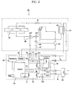
- FIG. 2 is a schematic configuration diagram illustrating a cogeneration system including an exhaust gas heat exchanger assembly according to an exemplary embodiment of the present invention.
- FIG. 3 is a schematic configuration diagram illustrating an internal structure of the exhaust gas heat exchanger assembly of the cogeneration system according to the illustrated embodiment of the present invention.
- the cogeneration system includes an engine 50, which operates using fossil fuel such as natural gas or petroleum gas, a generator 52 and an inverter 53 to generate electricity, using a driving force of the engine 50, first and second exhaust gas heat exchangers 92 and 95 arranged at an exhaust conduit 54 to recover heat of exhaust gas of the engine 50, a cooling water heat exchanger 72 to recover heat of cooling water of the engine 50, and a radiating heat exchanger 78 to radiate the cooling water heat.
- an engine 50 which operates using fossil fuel such as natural gas or petroleum gas
- a generator 52 and an inverter 53 to generate electricity, using a driving force of the engine 50
- first and second exhaust gas heat exchangers 92 and 95 arranged at an exhaust conduit 54 to recover heat of exhaust gas of the engine 50
- a cooling water heat exchanger 72 to recover heat of cooling water of the engine 50
- a radiating heat exchanger 78 to radiate the cooling water heat.
- the cogeneration system also includes a cooling/heating unit 60, which uses a heat pump type refrigerant cycle using waste heat generated from the engine 50.
- the cooling/heating unit 60 includes at least one compressor 61, a four-way valve 62, an outdoor heat exchanger 63, an expansion device 64, and an indoor heat exchanger 65, as in a general heat pump type cooling/heating unit, which can be used as both a cooling unit and a heating unit in accordance with reversal of a refrigerant flow in a refrigerant cycle of the cooling/heating unit.
- Fans (not shown), which are provided in association with the compressor 61, outdoor heat exchanger 63, and indoor heat exchanger 65, respectively, may be driven by the electricity supplied from the generator 52.
- an exhaust gas heat exchanger assembly 90 is arranged at the exhaust conduit 54, through which the exhaust gas of the engine 50 is discharged, as shown in FIG. 3.
- the exhaust gas heat exchanger assembly 90 includes a muffler 91 arranged at an intermediate portion of the exhaust conduit 54 to reduce exhaust noise, and exhaust tubes 93 and 96 respectively arranged at apposite sides of the muffler 91 to connect the muffler 91 to the exhaust conduit 54 such that the exhaust gas in the exhaust conduit 54 passes through the muffler 91.
- the first and second exhaust gas heat exchangers 92 and 95 are also included in the exhaust gas heat exchanger assembly 90.
- the first and second exhaust gas heat exchangers 92 and 95 are arranged at the opposite sides of the muffler 91 to perform heat exchange with the exhaust gas passing through the exhaust tubes 93 and 96, respectively.
- Each of the exhaust tubes 93 and 96 has a tube bundle structure to obtain an increased heat transfer rate in the interior of an associated one of the first and second exhaust gas heat exchangers 92 and 95.
- a flange 94 is provided at an inlet of the exhaust tube 93 corresponding to an upstream end of the first exhaust gas exchanger 92 so that the exhaust tube 93 and first exhaust gas exchanger 92 are coupled to the exhaust conduit 54 by means of the flange 94. Also, a connector 97 is provided at an outlet of the exhaust tube 96 corresponding to a downstream end of the second exhaust gas exchanger 95 so that the exhaust tube 96 and second exhaust gas exchanger 95 are coupled to the exhaust conduit 54 by means of the connector 97.
- the muffler 91 has a structure in which the interior of the muffler 91 is divided into a plurality of chambers by a plurality of membranes while being communicated with one another to define an elongated exhaust gas path, as in a general muffler structure.
- the muffler 91 includes two muffler cases provided, at facing ends thereof, with flanges 91a, and coupled to each other by means of the flanges 91a.
- the muffler 91 includes one or more noise reducing members 99 each arranged in an associated one of the muffler cases and made of a mesh member having a porous structure.
- noise absorbing members may also be provided, in addition to the mesh members.
- the first exhaust gas heat exchanger 92 is arranged upstream from the second exhaust gas heat exchanger 95 with respect to a flowing direction of the exhaust gas, to recover heat of a relatively high temperature.
- the second exhaust gas heat exchanger 95 which is arranged downstream from the first exhaust gas heat exchanger 92, recovers heat of a relatively low temperature.
- the exhaust gas heat exchangers 92 and 95 be designed to withstand an exhaust gas pressure of 600 mmAq or below.
- the first exhaust gas heat exchanger 92 must be designed such that the outlet exhaust gas temperature thereof ranges from 130°C to 150°C.
- the second exhaust gas heat exchanger 95 can effectively perform heat exchange with a refrigerant passing through the second exhaust gas heat exchanger 95, and thus, can discharge exhaust gas maintained at a temperature of 100°C or below.
- the cogeneration system also includes a pre-heat supplying means to supply the heat of cooling water used to cool the engine 50 and the heat of exhaust gas discharged from the engine 50 to the outdoor heat exchanger 63, and thus, to pre-heat air passing around the outdoor heat exchanger 63.
- the cooling water heat exchanger 72 is included in the pre-heat supplying means.
- the cooling water heat exchanger 72 is connected to the engine 50 via a cooling water line 71 to recover the cooling water heat of the engine 50.
- the first exhaust gas heat exchanger 92 which primarily recovers the heat of the exhaust gas discharged from the engine 50, is also included in the pre-heat supplying means.
- the pre-heat supplying means further includes a pre-heating heat exchanger 74 to pre-heat the outdoor heat exchanger 63, and a heat transfer line 73, which connects the cooling water heat exchanger 72, first exhaust gas heat exchanger 92, and pre-heating heat exchanger 74, to guide a heat transfer medium to pass through the exchangers 72, 92, and 74.
- a temperature sensor T is arranged at the heat transfer line 73 to sense the temperature of the heat transfer medium at an outlet of the first exhaust gas heat exchanger 92.
- a radiating means is also arranged at the heat transfer line 73 to radiate heat transferred from the cooling water heat exchanger 72 and first exhaust gas heat exchanger 92.
- the radiating means includes a radiating line 77 branched from the heat transfer line 73, valves 77v to change a fluid path between the heat transfer line 73 and the radiating line 77, and a radiating heat exchanger 78, through which the radiating line 77 extends to radiate heat.
- An external heat exchanger 83 is connected to the heat transfer line 73 via an external line 81 to receive the heat transferred from the cooling water heat exchanger 72 and first exhaust gas heat exchanger 92, and thus, to supply a heat source to an external system for hot water supply or other purposes.
- the cogeneration system further includes a refrigerant over-heating means to supply the heat of the exhaust gas discharged from the engine 50 to an inlet of the indoor heat exchanger 65 of the cooling/heating unit 60.
- the refrigerant over-heating means includes a heating line 67 branched from a refrigerant line 66 between the indoor heat exchanger 65 and the four-way valve 62, and valves 67v to change a refrigerant path between the refrigerant line 66 and the heating line 67.
- the refrigerant over-heating means also includes the second exhaust gas heat exchanger 95, which is arranged at the exhaust conduit 54 of the engine 50.
- the heating line 67 extends through the second exhaust gas heat exchanger 95, and performs heat exchange with the second exhaust gas heat exchanger 95.
- a flow rate control valve 68 is arranged at the heating line 67 to control the flow rate of the refrigerant flowing through the second exhaust gas heat exchanger 95.
- reference character P designates pumps, each serving to force the heat transfer medium to flow through an associated line.
- FIG. 2 Although the arrangement, in which a plurality of indoor heat exchangers 65 are connected to the single compressor 61, has been illustrated in FIG. 2, a plurality of compressors 61 or a plurality of outdoor heat exchangers 63 may be used. Also, although the cogeneration system has been illustrated as including one engine 50 and one cooling/heat unit 60, a plurality of cooling/heating units or a plurality of engine rooms may be used.
- the above-described heat exchangers may have various heat transfer configurations, for example, a heat transfer configuration in which heat transfer is carried out through a thermal conductor, or a heat transfer configuration in which heat transfer is carried out through a fluid present in a heat exchanger, in accordance with the given design condition or the given requirement.
- Electricity which is generated by a driving force from the engine 50, may be used to operate electricity consuming elements such as the compressor 61 of the cooling/heating unit 60 and diverse controllers.
- a refrigerant flows through the compressor 61, four-way valve 62, indoor heat exchanger 65, expansion device 64, and outdoor heat exchanger 63, in this order, to perform a heating operation.
- the cooling water heat and exhaust gas heat of the engine 50 are transferred to the pre-heating heat exchanger 74 via the cooling water heat exchanger 72 and first exhaust gas heat exchanger 92, so that the outdoor heat exchanger 63 is pre-heated. Accordingly, it is possible to prevent the heat exchanging performance of the outdoor heat exchanger 63 serving as an evaporator from being greatly degraded under the condition in which the ambient temperature is considerably low. Thus, an enhancement in heating performance is achieved.
- the refrigerant which is introduced into the indoor heat exchanger 65 via the second exhaust gas heat exchanger 95, is heated by the secondary exhaust gas heat. Accordingly, it is possible to enhance the heating performance of the indoor heat exchanger 65 serving as a condenser to heat a confined space.
- the flow rate of the refrigerant is appropriately controlled, using the valves 67v and flow rate control valve 68.
- the temperature of the heat transfer medium transferred to the pre-heating heat exchanger 74 is appropriately controlled by sensing the temperature of the heat transfer medium by the temperature sensor T, and changing the communication paths of the valves 77v and valves 81v respectively associated with the radiating heat exchanger 78 and external heat exchanger 83, based on the sensed temperature.
- valves 81v which are arranged at the external line 81, are opened to transfer heat to the external heat exchanger 83 via the external line 81, and thus, to enable the external heat exchanger 83 to heat water.
- the refrigerant flows through the compressor 61, four-way valve 62, outdoor heat exchanger 63, expansion device 64, indoor heat exchanger 65, four-way valve 62, and compressor 61, in this order, to perform the cooling operation.
- the heat transferred from the cooling water heat exchanger 72 and first exhaust gas heat exchanger 92 to the pre-heating heat exchanger 74 is cut off.
- the engine cooling water heat and exhaust gas heat are radiated through the radiating heat exchanger 78 and external heat exchanger 83.
- the communication paths of the valves 67v are also changed to prevent the refrigerant from flowing from the refrigerant line 66 between the indoor heat exchanger 65 and the four-way valve 62 to the bypass line 67 communicating with the second exhaust gas heat exchanger 95.
- the exhaust gas heat exchanger assembly 90 is configured such that the first and second exhaust gas heat exchangers 92 are arranged in serial, and the muffler 91 is arranged between the first and second exhaust gas heat exchangers 92, it is possible to reduce noise generated during discharge of the exhaust gas, and to obtain a more compact heat exchanger arrangement.
- the cogeneration system of the present invention includes an exhaust gas heat exchanger assembly in which a pair of heat exchangers are arranged at opposite sides of a muffler in an exhaust conduit of an engine such that the heat exchangers and muffler are integrated. Accordingly, it is possible to reduce exhaust noise, and thus, to achieve a more quiet system operation.
- the heat exchangers are arranged in a compact state, so that it is possible to reduce the volume of the cogeneration system and to enhance the utility of the cogeneration system.
Landscapes
- Engineering & Computer Science (AREA)
- Mechanical Engineering (AREA)
- General Engineering & Computer Science (AREA)
- Chemical & Material Sciences (AREA)
- Combustion & Propulsion (AREA)
- Physics & Mathematics (AREA)
- Thermal Sciences (AREA)
- Exhaust Silencers (AREA)
- Heat-Exchange Devices With Radiators And Conduit Assemblies (AREA)
- Heat-Pump Type And Storage Water Heaters (AREA)
- Air-Conditioning For Vehicles (AREA)
Applications Claiming Priority (1)
| Application Number | Priority Date | Filing Date | Title |
|---|---|---|---|
| KR1020040064812A KR100624815B1 (ko) | 2004-08-17 | 2004-08-17 | 코제너레이션 시스템의 배기가스 열교환기 |
Publications (2)
| Publication Number | Publication Date |
|---|---|
| EP1628100A2 true EP1628100A2 (de) | 2006-02-22 |
| EP1628100A3 EP1628100A3 (de) | 2011-10-05 |
Family
ID=36080259
Family Applications (1)
| Application Number | Title | Priority Date | Filing Date |
|---|---|---|---|
| EP05001038A Withdrawn EP1628100A3 (de) | 2004-08-17 | 2005-01-19 | Wärme-Kraft Kopplungssystem und Abgaswärmetauscher dafür |
Country Status (4)
| Country | Link |
|---|---|
| US (1) | US20060037351A1 (de) |
| EP (1) | EP1628100A3 (de) |
| KR (1) | KR100624815B1 (de) |
| CN (1) | CN100378414C (de) |
Cited By (5)
| Publication number | Priority date | Publication date | Assignee | Title |
|---|---|---|---|---|
| EP1882890A3 (de) * | 2006-07-25 | 2008-06-25 | LG Electronic Inc. | Kogeneration |
| EP1882891A3 (de) * | 2006-07-27 | 2008-06-25 | LG Electronics Inc. | Kogeneration |
| CN101501420B (zh) * | 2006-08-11 | 2011-03-16 | 大金工业株式会社 | 空调装置 |
| US8245948B2 (en) | 2006-07-25 | 2012-08-21 | Lg Electronics Inc. | Co-generation and control method of the same |
| US20180372333A1 (en) * | 2017-06-27 | 2018-12-27 | Imby Energy, Inc. | Cogeneration systems and methods for generating heating and electricity |
Families Citing this family (13)
| Publication number | Priority date | Publication date | Assignee | Title |
|---|---|---|---|---|
| KR20060112844A (ko) * | 2005-04-28 | 2006-11-02 | 엘지전자 주식회사 | 열병합 발전 시스템 |
| KR100624736B1 (ko) * | 2005-05-19 | 2006-09-15 | 엘지전자 주식회사 | 열병합 발전시스템 |
| WO2009048090A1 (ja) * | 2007-10-10 | 2009-04-16 | Yanmar Co., Ltd. | エンジン排気ガス熱回収器およびそれを使用したエネルギー供給装置 |
| EP2340405B1 (de) * | 2008-10-29 | 2018-06-13 | MAHLE International GmbH | Interne wärmetauscheranordnung mit einer internen entlüftungsventilanordnung |
| FR2948990A1 (fr) * | 2009-08-04 | 2011-02-11 | Mobile Comfort Holding | Dispositif thermodynamique multi-energie modulaire |
| CN102906506B (zh) * | 2009-12-08 | 2016-08-03 | 电动能源公司 | 热和电的分配以及热电联产的方法及系统 |
| JP5701026B2 (ja) * | 2010-11-29 | 2015-04-15 | 三菱重工業株式会社 | 排熱回収システム |
| US10036347B1 (en) * | 2013-07-19 | 2018-07-31 | Raymond C. Sherry | Standby energy generating system |
| CN105019989A (zh) * | 2015-07-09 | 2015-11-04 | 威迩徕德电力设备(上海)有限公司 | 一种热电联产机组烟水换热装置 |
| CN105332807B (zh) * | 2015-09-28 | 2018-03-20 | 百发动力(无锡)有限公司 | 热电联产内燃机发电机组的控制系统及其控制方法 |
| KR102620362B1 (ko) * | 2016-08-31 | 2024-01-04 | 삼성전자주식회사 | 공기조화기 |
| CN111433549A (zh) | 2017-07-17 | 2020-07-17 | 分形散热器技术有限责任公司 | 多重分形散热器系统及方法 |
| CN111022183A (zh) * | 2019-12-18 | 2020-04-17 | 周旭龙 | 热电联产系统 |
Citations (4)
| Publication number | Priority date | Publication date | Assignee | Title |
|---|---|---|---|---|
| DE1530559A1 (de) | 1965-04-13 | 1970-01-08 | Daimler Benz Ag | Absorptionskuehlanlage fuer Kraftfahrzeuge |
| US5966952A (en) | 1996-09-05 | 1999-10-19 | Yamaha Hatsudoki Kabushiki Kaisha | Heat pump system with balanced total heating-emitting and absorbing capacities and method for stable heat pumping operation |
| EP1202005A2 (de) | 2000-10-30 | 2002-05-02 | Mitsubishi Heavy Industries, Ltd. | Aussenwärmeaustauscheinheit, Ausseneinheit und Klimagerät der Art einer Gaswärmepumpe |
| DE20313863U1 (de) | 2003-09-06 | 2003-11-20 | AUTOTECHNIK GmbH Johanngeorgenstadt, 08349 Johanngeorgenstadt | Abgasanlage |
Family Cites Families (32)
| Publication number | Priority date | Publication date | Assignee | Title |
|---|---|---|---|---|
| US1745492A (en) * | 1925-12-31 | 1930-02-04 | Kelch Ventilating Heater Compa | Combined heater and muffler for automobiles |
| US3201934A (en) * | 1962-08-06 | 1965-08-24 | Harold W Smith | Exhaust-liquid heat exchanger for internal combustion engines |
| US3280903A (en) * | 1964-12-21 | 1966-10-25 | Universal Silencer Corp | Exhaust silencer and heat recovery unit |
| US3404731A (en) * | 1966-07-12 | 1968-10-08 | Paul A. Cushman | Combined exhaust silencer and heat exchanger |
| US4621681A (en) * | 1977-11-09 | 1986-11-11 | Q-Dot Corporation | Waste heat boiler |
| US4353207A (en) * | 1980-08-20 | 1982-10-12 | Westinghouse Electric Corp. | Apparatus for removing NOx and for providing better plant efficiency in simple cycle combustion turbine plants |
| JPS6131131Y2 (de) * | 1981-03-26 | 1986-09-10 | ||
| US4391235A (en) * | 1981-05-28 | 1983-07-05 | Majkrzak David S | Vehicle exhaust gas warm-up heater system |
| EP0111538A4 (de) * | 1982-06-10 | 1985-02-28 | Edwin A Price | Rippenwärmetauscher. |
| US4450932A (en) * | 1982-06-14 | 1984-05-29 | Nelson Industries, Inc. | Heat recovery muffler |
| JPS59217491A (ja) * | 1983-05-25 | 1984-12-07 | Kogata Gas Reibou Gijutsu Kenkyu Kumiai | 排ガス用熱交換器 |
| DE3708238A1 (de) * | 1987-03-16 | 1988-09-29 | Motoren Werke Mannheim Ag | Kraft-waerme-kopplungsanlage |
| US4896830A (en) * | 1987-09-30 | 1990-01-30 | Kubota Ltd. | Waste heat recovery system for horizontal liquid-cooled internal combustion engine |
| US4896500A (en) * | 1989-05-15 | 1990-01-30 | Westinghouse Electric Corp. | Method and apparatus for operating a combined cycle power plant having a defective deaerator |
| US5033264A (en) * | 1989-06-16 | 1991-07-23 | Tecogen Inc. | Compact cogeneration system |
| US5314009A (en) * | 1992-10-08 | 1994-05-24 | Gas Research Institute | Exhaust gas recuperator |
| US5320166A (en) * | 1993-01-06 | 1994-06-14 | Consolidated Natural Gas Service Company, Inc. | Heat pump system with refrigerant isolation and heat storage |
| US5429179A (en) * | 1993-08-23 | 1995-07-04 | Gas Research Institute | Gas engine driven heat pump system having integrated heat recovery and auxiliary components |
| US5729985A (en) * | 1994-12-28 | 1998-03-24 | Yamaha Hatsudoki Kabushiki Kaisha | Air conditioning apparatus and method for air conditioning |
| US5709201A (en) * | 1995-10-03 | 1998-01-20 | Anser Thermal Technologies, Inc. | Method and apparatus for heating a liquid medium |
| US6085513A (en) * | 1996-01-17 | 2000-07-11 | International Power Technology | Method and apparatus for bypassing the superheater in a dual fluid engine |
| FR2770582B1 (fr) * | 1997-10-31 | 2000-01-28 | Valeo Thermique Moteur Sa | Ligne d'echappement et de recirculation des gaz pour moteur de vehicule automobile |
| DE19813674C1 (de) * | 1998-03-27 | 1999-04-15 | Daimler Chrysler Ag | Vorrichtung und Verfahren zum Heizen und Kühlen eines Nutzraumes eines Kraftfahrzeuges |
| US6151891A (en) * | 1998-09-22 | 2000-11-28 | Bennett; Easton | Heat exchanger for a motor vehicle exhaust |
| JP4337960B2 (ja) * | 1998-12-17 | 2009-09-30 | ゼネラル・エレクトリック・カンパニイ | コンバインドサイクルシステムにおいて補助蒸気を供給するための装置及び方法 |
| US20030182955A1 (en) * | 1999-06-07 | 2003-10-02 | Toyotaka Hirao | Vehicular air conditioner |
| EP1065347B1 (de) * | 1999-07-01 | 2007-03-07 | General Electric Company | Vorrichtung zur Befeuchtung und Heizung von Brenngas |
| JP2001280745A (ja) * | 2000-03-31 | 2001-10-10 | Mitsubishi Heavy Ind Ltd | 空気調和装置 |
| JP2001324240A (ja) * | 2000-05-18 | 2001-11-22 | Sanyo Electric Co Ltd | マルチエネルギーシステム |
| PL341185A1 (en) * | 2000-07-03 | 2001-09-24 | Stanislaw Stanaszek | Silencer |
| US6460360B2 (en) * | 2001-02-20 | 2002-10-08 | Sheng-Ming Hsieh | Power-generating and energy-saving system |
| JP2005512011A (ja) * | 2001-12-12 | 2005-04-28 | クォンタム エナジー テクノロジーズ プロプライアトリー リミテッド | 給湯と空気調節のための省エネ式ヒートポンプシステム |
-
2004
- 2004-08-17 KR KR1020040064812A patent/KR100624815B1/ko not_active Expired - Fee Related
-
2005
- 2005-01-19 EP EP05001038A patent/EP1628100A3/de not_active Withdrawn
- 2005-02-01 US US11/046,750 patent/US20060037351A1/en not_active Abandoned
- 2005-02-17 CN CNB200510008340XA patent/CN100378414C/zh not_active Expired - Fee Related
Patent Citations (4)
| Publication number | Priority date | Publication date | Assignee | Title |
|---|---|---|---|---|
| DE1530559A1 (de) | 1965-04-13 | 1970-01-08 | Daimler Benz Ag | Absorptionskuehlanlage fuer Kraftfahrzeuge |
| US5966952A (en) | 1996-09-05 | 1999-10-19 | Yamaha Hatsudoki Kabushiki Kaisha | Heat pump system with balanced total heating-emitting and absorbing capacities and method for stable heat pumping operation |
| EP1202005A2 (de) | 2000-10-30 | 2002-05-02 | Mitsubishi Heavy Industries, Ltd. | Aussenwärmeaustauscheinheit, Ausseneinheit und Klimagerät der Art einer Gaswärmepumpe |
| DE20313863U1 (de) | 2003-09-06 | 2003-11-20 | AUTOTECHNIK GmbH Johanngeorgenstadt, 08349 Johanngeorgenstadt | Abgasanlage |
Cited By (9)
| Publication number | Priority date | Publication date | Assignee | Title |
|---|---|---|---|---|
| EP1882890A3 (de) * | 2006-07-25 | 2008-06-25 | LG Electronic Inc. | Kogeneration |
| US8245948B2 (en) | 2006-07-25 | 2012-08-21 | Lg Electronics Inc. | Co-generation and control method of the same |
| EP1882891A3 (de) * | 2006-07-27 | 2008-06-25 | LG Electronics Inc. | Kogeneration |
| CN101501420B (zh) * | 2006-08-11 | 2011-03-16 | 大金工业株式会社 | 空调装置 |
| US20180372333A1 (en) * | 2017-06-27 | 2018-12-27 | Imby Energy, Inc. | Cogeneration systems and methods for generating heating and electricity |
| US20180372337A1 (en) * | 2017-06-27 | 2018-12-27 | Imby Energy, Inc. | Cogeneration systems and methods for generating heating and electricity |
| US11041637B2 (en) * | 2017-06-27 | 2021-06-22 | Imby Energy, Inc. | Cogeneration systems and methods for generating heating and electricity |
| US11041635B2 (en) * | 2017-06-27 | 2021-06-22 | Imby Energy, Inc. | Cogeneration systems and methods for generating heating and electricity |
| US11041636B2 (en) * | 2017-06-27 | 2021-06-22 | Imby Energy, Inc. | Cogeneration systems and methods for generating heating and electricity |
Also Published As
| Publication number | Publication date |
|---|---|
| CN1737344A (zh) | 2006-02-22 |
| EP1628100A3 (de) | 2011-10-05 |
| CN100378414C (zh) | 2008-04-02 |
| US20060037351A1 (en) | 2006-02-23 |
| KR20060016393A (ko) | 2006-02-22 |
| KR100624815B1 (ko) | 2006-09-20 |
Similar Documents
| Publication | Publication Date | Title |
|---|---|---|
| US20060037351A1 (en) | Cogeneration system and exhaust gas heat exchanger assembly thereof | |
| KR100579574B1 (ko) | 코제너레이션 시스템 | |
| US7275382B2 (en) | Cogeneration system | |
| US7170191B2 (en) | Electricity generating and air conditioning system with water heater | |
| EP1628091A2 (de) | Klimaanlage kombiniert mit einem elektrizitäterzeugungsystem | |
| EP1628099B1 (de) | Wärme-Kraft-System und Verfahren für dessen Steuerung | |
| KR100657471B1 (ko) | 코제너레이션 시스템 | |
| KR100591320B1 (ko) | 코제너레이션 시스템을 이용한 냉난방 장치 | |
| EP1628104A2 (de) | Wärme-Kraft-System | |
| US7240504B2 (en) | Cogeneration system | |
| EP4306855A1 (de) | Wärmepumpensystem mit doppelwärmetauschertank | |
| KR20220100345A (ko) | 열병합발전 시스템 | |
| CN116638922A (zh) | 一种新能源热管理系统及热管理方法 | |
| US7243504B2 (en) | Cogeneration system | |
| EP1628097A2 (de) | Klimaanlage kombiniert mit einem elektrizitäterzeugungsystem | |
| CN1995855A (zh) | 空气源热泵空调热水器 | |
| CN219415055U (zh) | 热泵空调系统 | |
| CN111764981B (zh) | 发电系统 | |
| KR100657498B1 (ko) | 열병합 발전 시스템 | |
| CN118789998A (zh) | 阀组件、热管理系统及车辆 |
Legal Events
| Date | Code | Title | Description |
|---|---|---|---|
| PUAI | Public reference made under article 153(3) epc to a published international application that has entered the european phase |
Free format text: ORIGINAL CODE: 0009012 |
|
| 17P | Request for examination filed |
Effective date: 20050119 |
|
| AK | Designated contracting states |
Kind code of ref document: A2 Designated state(s): AT BE BG CH CY CZ DE DK EE ES FI FR GB GR HU IE IS IT LI LT LU MC NL PL PT RO SE SI SK TR |
|
| AX | Request for extension of the european patent |
Extension state: AL BA HR LV MK YU |
|
| PUAL | Search report despatched |
Free format text: ORIGINAL CODE: 0009013 |
|
| AK | Designated contracting states |
Kind code of ref document: A3 Designated state(s): AT BE BG CH CY CZ DE DK EE ES FI FR GB GR HU IE IS IT LI LT LU MC NL PL PT RO SE SI SK TR |
|
| AX | Request for extension of the european patent |
Extension state: AL BA HR LV MK YU |
|
| RIC1 | Information provided on ipc code assigned before grant |
Ipc: F28D 21/00 20060101ALI20110830BHEP Ipc: F01N 5/02 20060101ALI20110830BHEP Ipc: F01N 1/08 20060101ALI20110830BHEP Ipc: F02G 5/04 20060101ALI20110830BHEP Ipc: F25B 27/02 20060101AFI20110830BHEP |
|
| AKX | Designation fees paid |
Designated state(s): DE FR GB |
|
| GRAP | Despatch of communication of intention to grant a patent |
Free format text: ORIGINAL CODE: EPIDOSNIGR1 |
|
| STAA | Information on the status of an ep patent application or granted ep patent |
Free format text: STATUS: THE APPLICATION IS DEEMED TO BE WITHDRAWN |
|
| 18D | Application deemed to be withdrawn |
Effective date: 20130305 |