EP1628411A2 - Système de messagerie sans fil - Google Patents
Système de messagerie sans fil Download PDFInfo
- Publication number
- EP1628411A2 EP1628411A2 EP05254929A EP05254929A EP1628411A2 EP 1628411 A2 EP1628411 A2 EP 1628411A2 EP 05254929 A EP05254929 A EP 05254929A EP 05254929 A EP05254929 A EP 05254929A EP 1628411 A2 EP1628411 A2 EP 1628411A2
- Authority
- EP
- European Patent Office
- Prior art keywords
- time
- recited
- signal
- access point
- lock
- Prior art date
- Legal status (The legal status is an assumption and is not a legal conclusion. Google has not performed a legal analysis and makes no representation as to the accuracy of the status listed.)
- Withdrawn
Links
Images

Classifications
-
- G—PHYSICS
- G07—CHECKING-DEVICES
- G07C—TIME OR ATTENDANCE REGISTERS; REGISTERING OR INDICATING THE WORKING OF MACHINES; GENERATING RANDOM NUMBERS; VOTING OR LOTTERY APPARATUS; ARRANGEMENTS, SYSTEMS OR APPARATUS FOR CHECKING NOT PROVIDED FOR ELSEWHERE
- G07C9/00—Individual registration on entry or exit
-
- G—PHYSICS
- G07—CHECKING-DEVICES
- G07C—TIME OR ATTENDANCE REGISTERS; REGISTERING OR INDICATING THE WORKING OF MACHINES; GENERATING RANDOM NUMBERS; VOTING OR LOTTERY APPARATUS; ARRANGEMENTS, SYSTEMS OR APPARATUS FOR CHECKING NOT PROVIDED FOR ELSEWHERE
- G07C9/00—Individual registration on entry or exit
- G07C9/20—Individual registration on entry or exit involving the use of a pass
- G07C9/27—Individual registration on entry or exit involving the use of a pass with central registration
-
- G—PHYSICS
- G07—CHECKING-DEVICES
- G07C—TIME OR ATTENDANCE REGISTERS; REGISTERING OR INDICATING THE WORKING OF MACHINES; GENERATING RANDOM NUMBERS; VOTING OR LOTTERY APPARATUS; ARRANGEMENTS, SYSTEMS OR APPARATUS FOR CHECKING NOT PROVIDED FOR ELSEWHERE
- G07C2209/00—Indexing scheme relating to groups G07C9/00 - G07C9/38
- G07C2209/06—Involving synchronization or resynchronization between transmitter and receiver; reordering of codes
-
- G—PHYSICS
- G07—CHECKING-DEVICES
- G07C—TIME OR ATTENDANCE REGISTERS; REGISTERING OR INDICATING THE WORKING OF MACHINES; GENERATING RANDOM NUMBERS; VOTING OR LOTTERY APPARATUS; ARRANGEMENTS, SYSTEMS OR APPARATUS FOR CHECKING NOT PROVIDED FOR ELSEWHERE
- G07C2209/00—Indexing scheme relating to groups G07C9/00 - G07C9/38
- G07C2209/60—Indexing scheme relating to groups G07C9/00174 - G07C9/00944
- G07C2209/61—Signal comprising different frequencies, e.g. frequency hopping
-
- G—PHYSICS
- G07—CHECKING-DEVICES
- G07C—TIME OR ATTENDANCE REGISTERS; REGISTERING OR INDICATING THE WORKING OF MACHINES; GENERATING RANDOM NUMBERS; VOTING OR LOTTERY APPARATUS; ARRANGEMENTS, SYSTEMS OR APPARATUS FOR CHECKING NOT PROVIDED FOR ELSEWHERE
- G07C9/00—Individual registration on entry or exit
- G07C9/00174—Electronically operated locks; Circuits therefor; Nonmechanical keys therefor, e.g. passive or active electrical keys or other data carriers without mechanical keys
- G07C9/00896—Electronically operated locks; Circuits therefor; Nonmechanical keys therefor, e.g. passive or active electrical keys or other data carriers without mechanical keys specially adapted for particular uses
- G07C9/00904—Electronically operated locks; Circuits therefor; Nonmechanical keys therefor, e.g. passive or active electrical keys or other data carriers without mechanical keys specially adapted for particular uses for hotels, motels, office buildings or the like
-
- H—ELECTRICITY
- H04—ELECTRIC COMMUNICATION TECHNIQUE
- H04B—TRANSMISSION
- H04B1/00—Details of transmission systems, not covered by a single one of groups H04B3/00 - H04B13/00; Details of transmission systems not characterised by the medium used for transmission
- H04B1/69—Spread spectrum techniques
- H04B1/713—Spread spectrum techniques using frequency hopping
Definitions
- the present invention relates to a security system, and more particularly to a method of communicating information to electronic door locks within a multi-room facility.
- Multi-room facilities typically control access to rooms in the facility with electronic door locks.
- Electronic keys to actuate the electronic door locks provide access to the rooms in the facility.
- an electronic key is programmed to actuate the electronic door lock of that room.
- Programming the electronic key to the electronic lock usually requires direct access to the electronic lock. For instance, when a new resident of the room replaces a previous resident of the room the new resident is given a newly programmed key. The new resident proceeds to the room and inserts the newly programmed key into the electronic lock. The electronic lock recognizes the newly programmed key and the electronic lock reprograms accordingly. Previous versions of programmed keys may not actuate the lock, preventing the old resident of the room from accessing the room.
- a battery powers the electronic locks. It is not desirable for the electronic locks to remain fully powered at all times. Instead, it is desirable for the electronic locks to enter a sleep mode (an energy conserving mode) when full battery power is not needed.
- a light combination on the electronic lock identifies low battery power; however, viewing the light combination requires direct access to the electronic lock.
- the wireless messenger system of the current invention includes a method of communicating between electronic door locks, access point hubs and a central controller.
- the method includes transmitting a probe signal from a electric door lock to a central controller, or access point hub receiver in several different frequencies.
- the access point hub detects the probe signal and transmits a probe response back to the electric door lock.
- the probe signal and probe response associate the electric door lock with the receiver thereby synchronizing the electronic door lock with the central controller and access point hub. Synchronizing between the electronic door locks, the access point hub and the central controller are based on the probe signal and the probe response.
- the probe signal may be shorter than the frequency dwell time of the several different frequencies and the probe response may include the transmission time of the probe response.
- Recording the transmission time takes place after detecting the probe signal and transmitting the probe response. Recording the transmission time partially determines the difference between the time the probe response was transmitted and the time the probe response was received. Adjustments are then made to the time of the receiver associated with the electronic lock based on the difference.
- Synchronization is confirmed by monitoring a blanking period.
- the blanking period is of a time that is adjusted to accommodate drift between frequencies.
- the inventive method provides for interrogation and communication between electronic locks that conserves battery consumption and tracks usage.
- FIG 1 is a general schematic view of a security system 10 for a multi-room facility, schematically shown at 24, that utilizes radio frequency signals to communicate from multiple electronic lock stations 12 corresponding to each room of the facility 24.
- the system 10 includes the electronic lock stations 12 along with several access point hubs 14. Communications between the access point hub 14 and the lock stations 12 take place via a two-way radio frequency signal 18.
- the lock station 12 and the access point hub 14 both include a transceiver 16.
- the transceivers 16 send and accept the radio frequency signals 18 that are sent from either the lock stations 12 or the access point hubs 14.
- the lock station 12 and the access point hub 14 communicate using a frequency hopping protocol to provide consistent and reliable communication while conserving battery power at the lock stations 12.
- the radio frequency signal 18 is sent according to this invention to communicate between the access point hub 14 and the lock stations 12 information indicative of lock operation and programming. Such information includes key 26 identification and tracking, historical records, and key 26 programming. As appreciated information communicated to and from the lock stations 12 can include any number and types of information.
- the communication method according to this invention provides for the avoidance of collisions with other radio frequency signals 18 by hopping from frequency to frequency within a predetermined frequency band.
- the lock station 12 typically sends communications to the access point hub 14 relaying status of the lock station 12. For instance, the lock station 12 may need to communicate that a battery 20 powering the lock station 12 has lost power. Using the communication method of this invention, the lock station 12 communicates this information to the access point hub 14. The access point hub 14 receives and displays this information by way of central controller 22 to notify an operator of the condition of the lock station 12, i.e. in this example that the battery 20 should be replaced. The central controller 22 can display a status of multiple lock stations 12 collected from multiple access point hubs 14 in the multi-room facility 24.
- the access point hub 14 also sends communications to the lock station 12. For example, it may be necessary to remotely reprogram the lock station 12 to accept a key card 26. Reprogramming can be initiated at the central controller 22, and communicated to the lock station 12 from the access point hub 14 using the communication method of the current invention.
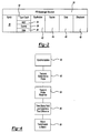
- the radio frequency signal includes a data packet illustrated schematically at 28.
- the data packet 28 is sent between the electronic lock 12, the access point hub 14 and the central controller 22.
- the data packet 28 includes a synch field 30, and type-count field 32, a destination field 42 a source field 44 a data field 46 and a checksum field 48.
- the synch field 30 is a preamble field transmitted before the actual data packet 28 and intended to stabilize the transmitting device, i.e. lock station 12 or access point hub 14. Stabilizing the transmitting device reduces the possibility that the receiving device will not be synchronized once data begins being transmitted.
- the type-count field 32 provides information on the type of packet that is being transmitted. Further the type-count field 32 also includes information on the number of data bytes that are contained within the data packet 28.
- the type of data packet can include a management packet 34 that provides for management of internal operation of the lock station 12. Such internal operations can include probe requests, probe responses association requests and response.
- Each of the management type packets is acknowledged by the receiving device.
- Another type of packet is a control packet 36 that is used to control the flow of information and commands. Such control provides instructions such as when it is clear to send as well as acknowledge response.
- the control packet 36 is not a type of data packet that is acknowledged. Further, packets 38 are sent to transfer data as desired between devices. The receiving device will acknowledge receipt of the packet 38.
- the destination field 42 contains the address of the device to which the data packet is to be sent.
- the destination field 42 includes instructions on the type of device, i.e. access hub 14 or lock station 12, along with an identifier specific to an individual device.
- the source field 44 corresponds to the destination field 42 in that it provides information on the device that is sending the data packet 28.
- the data field 46 contains information utilized to instruct and inform the receiving device, such as key codes, identification codes and history data.
- the checksum field 48 is transmitted at the end of the packet and provides for the validation of the integrity of the data packet 28.
- the use of multiple lock stations 12 in relatively close proximity to a plurality of access hubs 14 can in some instance cause data packets 28 from various lock stations to arrive at an intended access hub 14 at the same time.
- the resulting data collision renders the transmission useless and such data must be resent.
- the way in which data is resent must be varied in some manner or subsequent collisions will occur.
- the communication method according to this method includes a protocol for preventing data collisions by varying the time at which data transmission are sent for subsequent data packets 28.
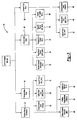
- FIG. 3 is a schematic that illustrates the method of communication 50 according to the current invention.
- An initial step is a hardware start-up initialization step 52 that provides for activating the required hardware including the electronic lock 12, the access point hub 14 and the central controller 22.
- the central controller 22 would be active at all times and therefore would only rarely be shut down such that an initialization is required.
- the access point hubs 14 are active and infrequently require initialization.
- the individual lock stations 12, however, are shutdown or put into a sleep mode to conserve battery power.
- the start-up initialization step 52 includes the steps of initializing the system hardware 60, initializing a timing module in the system hardware 62 and initializing a data link layer (DLL) module 64.
- Initializing the system hardware includes powering up the lock station 12 or the access point hub 14.
- a timing module is then initialized as shown at step 62 to begin timed operations for the communication protocol according to this invention.
- the data link layer 64 is initialized to provide the links required for the method according to this invention.
- the initial work step 54 includes the steps of enabling the system timer 66, opening the serial communications channel 68 and opening the radio frequency communications channel 70.
- the enabling step for the system timer 66 prepares the communication system for receipt of radio frequency signals.
- the steps of opening the serial communication channel 68 and of opening the radio frequency communication channel 70 prepare the lock station 12 or the access point hub 14 for operation.
- the lock station 12 and the access point hub 14 perform many of the same initial operation functions in preparation for receiving communications.
- a main work step indicated at 56 functions to process the data packets 28 received via the serial or radio frequency port.
- the main work step 56 includes the steps of monitoring the lock station 12 or the access point hub 14, as indicated at 72 and reading the data packets as indicated at 74.
- the now received data packets are processed as indicated at 76.
- the main work step also includes the steps of reading and processing radio frequency packets as indicated at 78 and 80.
- the last step in the process comprises a final work step indicated at 58 that provides for returning the to the start-up initialization step 52.
- the final work step 58 includes the step of closing the RF Port 82, closing the serial port 84 and disabling the timer 86.
- the final work step 58 provides for the shut down of the device to prevent transmission and receipt of any signals.
- the lock stations 12 operate in a reduced power mode to conserve battery power.
- the lock station 12 will remain dormant until either a transmission from the access point hub 14 instructs the lock station to 12 to wake up, or until a desired time passes.
- the lock station 12 remains dormant and awakes to confirm communications with an access point hub 14. In some instances synchronization may be required as will be explained below.
- the access point hub 14 may send a transmission that awakes the lock station 12 to provide instruction. In any of these cases, the lock station 12 will continue operations for a desired time, or until activity stops, and become dormant to conserve battery power and increase the operational life of the lock station battery 20.
- the method of this invention provides for the synchronization of data transmission between devices, and also prevents the collision of data packets transmitted from multiple lock stations 12 to an access point hub 14.
- the steps of synchronization are schematically indicated at 90, and include the initial step of sensing the access point hub 14 prior to sending a data packet 28.
- the synchronization or frequency hopping protocol is required to synchronize a lock station 12 with one of the plurality of access point hubs14.
- the process begins with the lock station 12 transmitting a global active probe as indicated at 92.
- the global active probe 92 includes short probe requests emitted at short durations across several different frequencies across a desired frequency range.
- the probe requests are utilized to search for the corresponding access point hub 12.
- the length of the probes is of such duration as to allow multiple probe requests to fit within a frequency dwell time used by the access point hub 14.
- the access point hub 14 will respond to the probe request by transmitting a probe response as indicated at 94.
- a probe response is emitted back to the lock station 12 depending on the strength of the signal.
- several access point hubs 14 within the facility 24 may actually receive the probe request. However, only one will receive the signal at desired signal strength. Accordingly, only the access point hub 14 that receives the probe at the desired signal strength will transmit a probe response.
- the probe response includes information required to synchronize communication between the lock station 12 and the access point hub 14. Such information includes a field containing the actual time of transmission of the probe response.
- the probe response is transmitted in such a manner as to avoid the introduction of timing errors potentially caused by background functions.
- the lock station 12 Upon reception of the probe response, the lock station 12 will time stamp the actual time of receipt as indicated at 96.
- the lock station 12 now includes a time value for the time of transmission and a time stamp for the time of receipt of the probe response.
- the two time values are compared to determine a difference between the time response and the time it was received taking into account the speed of communication as well as the length of the data packet transmitted.
- the time difference is then used to adjust the transmitter 16 to match the access point hub 14 as indicated at 98. Once this is complete the lock station 12 and the access point hub are synchronized.
- the lock station 12 and the access point hub 14 remain synchronized until inherent relative inaccuracies between the two devices cause communication at different frequencies.
- An accommodation for such an occurrence is provided by a blanking period.
- the blanking period is a period that begins after a frequency switch and lasts a period determined to accommodate the maximum allowed drift between the transmission time and the receipt time.
- the method according to this invention includes monitoring this time and renewing the resynchronization between the two devices responsive to a detected shift.
- a directed probe request is sent instead of the global probe request sent during initial synchronization. This is possible because the specific access point hub 14 to which data is desired to be sent is known.
- the directed probe request is sent at the current frequency, a previous frequency or the next frequency depending on the success of resynchronization.
- the directed probe request utilizes information from previous successful communications to reestablish the communication link. In the event that the communication cannot be reestablished, the lock station 12 will, after a desired number of tries or time interval, will begin all over by transmitting a global probe request to begin a completely new resynchronization sequence.
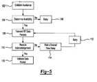
- the collision avoidance method 102 operates to prevent data packets 28 from different lock stations 12 from arriving at the access point hub 14 at the same time, and also to accommodate situations were collisions do occur.
- the lock station 12 will first determine availability of the access point hub 14 as indicated at 104. Determining availability is accomplished by sensing activity of the access point hub 14. If a device is determined to be unavailable, the lock station 12 will retry until the device is available as is indicated at 106.
- the lock station transmits the data packet 28 as indicated at 108.
- the access point hub 14 will transmit an acknowledgment of receipt of the data packet 28 as indicated at 110. In the absence of such an acknowledgement, the lock station 12 will consider the transmission a failure.
- the lock station will retry the transmission as indicated at 112. However, the next transmission will be transmitted at a time delay as indicated at 114.
- the time delay 114 is a period selected at random from a desired range. The use of the time delay for the next transmission at a random value substantially prevents subsequent sequential collisions that might occur if each lock station continued to send transmissions in a similar manner. Such a random time delay provides a better opportunity for subsequent transmission to be successful.
- the range of potential time delays is expanded with subsequent failed transmissions to increase the potential for completing the transmission. In other words, the time delay is initially randomly selected from a relatively small range of variables. The range of variables is increased with each try until a successful transmission is accomplished. In the event that subsequent transmission are not successful, the lock station 12 is instructed to limit the number of attempts to a desired number of attempts to prevent continuous attempts that would occur in the event that another error or problem with the lock station 12 or access point hub 14 has occurred.
- the validation step 116 includes the sequence of a transmitted data packet 28 and an acknowledgement.
- the sequence is not divisible and therefore is not interrupted by transmission from other devices.
- the time required for the sequence places a time limitation on the time allowed for the access point hub 14 and lock station 12 to complete a transmission and validate that data packet 28.
- the time between transmission and acknowledgment is smaller than the time required by a lock station 12 to detect that the access point hub 14 is available to accept a transmission. This is so, such that another lock station 12 will never interpret the time between a transmission and acknowledgment as an available access point hub 14 and send a transmission, thereby causing a potential collision of data packets 28. Further, this also provides that the acknowledgment sent responsive to the transmission is related to that transmission, and not to a separate transmission sent within any idle period.
- the method of this invention provides for continuous monitoring of radio frequency activity for the access point hub 14.
- the access point hub 14 sets a flag that is used to indicate availability.
- the example method is described and illustrated as communication between a lock station 12 and an access point hub 14, other devices and combination are also within the contemplation of this invention, such as for example, communication between an access point hub 14 and the central controller 22, or communications from the access point hub 14 and a lock station 12.
- the method and system of this invention determines idle time for the access point hub 14 by using bit time for the measurement of RF activity time.
- the time delays are converted to the equivalent number of RF bits then handled by counters 100 within each device.
- the counters 100 are continuously updated at the bit level to determine availability of the access point hub 14 or lock station 12.
- the use of the RF bits provides for the monitoring and updating of random back-off counter when collision errors are detected.
- the back-off counter provides time information to determine the random time delay utilized to reestablish communication.
Landscapes
- Physics & Mathematics (AREA)
- General Physics & Mathematics (AREA)
- Mobile Radio Communication Systems (AREA)
- Selective Calling Equipment (AREA)
Applications Claiming Priority (1)
| Application Number | Priority Date | Filing Date | Title |
|---|---|---|---|
| US60240904P | 2004-08-18 | 2004-08-18 |
Publications (2)
| Publication Number | Publication Date |
|---|---|
| EP1628411A2 true EP1628411A2 (fr) | 2006-02-22 |
| EP1628411A3 EP1628411A3 (fr) | 2006-10-04 |
Family
ID=35385561
Family Applications (1)
| Application Number | Title | Priority Date | Filing Date |
|---|---|---|---|
| EP05254929A Withdrawn EP1628411A3 (fr) | 2004-08-18 | 2005-08-06 | Système de messagerie sans fil |
Country Status (3)
| Country | Link |
|---|---|
| US (1) | US20060038654A1 (fr) |
| EP (1) | EP1628411A3 (fr) |
| CN (1) | CN1760493A (fr) |
Cited By (5)
| Publication number | Priority date | Publication date | Assignee | Title |
|---|---|---|---|---|
| WO2007059764A3 (fr) * | 2005-11-28 | 2007-07-05 | Astra Ges Fuer Asset Man Mbh | Systeme de securite |
| CN101833802A (zh) * | 2010-04-02 | 2010-09-15 | 杭州英杰电子有限公司 | 干电池供电的大型实时无线联网门禁系统 |
| US20100307206A1 (en) * | 2009-06-08 | 2010-12-09 | Harrow Products Llc | Electronic door lock for reduced power consumption |
| EP3276108B1 (fr) * | 2008-06-17 | 2022-03-23 | Digilock Asia Ltd. | Serrure electronique pour portes d'armoire, tiroirs et autres applications |
| US12020522B2 (en) | 2006-05-31 | 2024-06-25 | Security People, Inc. | Electronic cam lock for cabinet doors, drawers and other applications |
Families Citing this family (14)
| Publication number | Priority date | Publication date | Assignee | Title |
|---|---|---|---|---|
| US20110276609A1 (en) | 2001-12-27 | 2011-11-10 | Denison William D | Method for Controlling and Recording the Security of an Enclosure |
| US8354914B2 (en) * | 2005-01-27 | 2013-01-15 | Inncom International, Inc. | Reduced power electronic lock system |
| US20060164205A1 (en) * | 2005-01-27 | 2006-07-27 | Buckingham Duane W | Proximity wake-up activation of electronic circuits |
| US20070096872A1 (en) * | 2005-08-18 | 2007-05-03 | Gto, Inc. | Access control system and method |
| US20110254661A1 (en) | 2005-12-23 | 2011-10-20 | Invue Security Products Inc. | Programmable security system and method for protecting merchandise |
| TWI288548B (en) * | 2006-02-23 | 2007-10-11 | Ind Tech Res Inst | Multicast packet transmitting method of wireless network |
| US8063734B2 (en) * | 2006-11-06 | 2011-11-22 | Harrow Products Llc | Access control system wherein the remote device is automatically updated with a central user list from the central station upon use of the remote device |
| EP2098998B1 (fr) * | 2008-03-03 | 2016-05-25 | DORMA Deutschland GmbH | Système de contrôle d'accès et procédé de fonctionnement d'un tel système |
| CN102061840B (zh) * | 2009-11-16 | 2012-10-03 | 珠海优特电力科技股份有限公司 | 一种智能闭锁系统及其工作方法 |
| US9516006B2 (en) * | 2013-10-23 | 2016-12-06 | Google Inc. | Re-programmable secure cryptographic device |
| BR112017013997B1 (pt) | 2014-12-29 | 2022-06-28 | Invue Security Products Inc | Sistema de segurança de mercadoria e método para proteger um item de mercadoria suscetível a furto |
| US9888346B2 (en) * | 2015-09-18 | 2018-02-06 | Hyatt Corporation | Power management system for access control devices |
| WO2017181137A1 (fr) | 2016-04-15 | 2017-10-19 | Mobile Tech, Inc. | Commande d'autorisation pour système de sécurité antivol |
| US11639617B1 (en) | 2019-04-03 | 2023-05-02 | The Chamberlain Group Llc | Access control system and method |
Family Cites Families (11)
| Publication number | Priority date | Publication date | Assignee | Title |
|---|---|---|---|---|
| US5528621A (en) * | 1989-06-29 | 1996-06-18 | Symbol Technologies, Inc. | Packet data communication system |
| US5933086A (en) * | 1991-09-19 | 1999-08-03 | Schlage Lock Company | Remotely-operated self-contained electronic lock security system assembly |
| US5519717A (en) * | 1994-08-24 | 1996-05-21 | The United States Of America As Represented By The Secretary Of The Army | Method for time drift reduction of frequency hopping network clock |
| JP3581430B2 (ja) * | 1995-05-18 | 2004-10-27 | キヤノン株式会社 | 無線交換システムおよび通信装置、通信方法 |
| US5663957A (en) * | 1995-07-12 | 1997-09-02 | Ericsson Inc. | Dual mode satellite/cellular terminal |
| DE19941428B4 (de) * | 1998-09-02 | 2015-09-10 | Marquardt Gmbh | Schließsystem, insbesondere für ein Kraftfahrzeug |
| DE10011035C2 (de) * | 2000-03-07 | 2003-04-30 | Simons & Voss Gmbh | Schließanlagensystem und Verfahren zum Datenaustausch in einem Schließanlagensystem |
| DE10134837A1 (de) * | 2001-07-17 | 2003-01-30 | Hella Kg Hueck & Co | Verfahren zum fernbedienten Ver- und/oder Entriegeln eines Fahrzeuges |
| US7248836B2 (en) * | 2001-09-30 | 2007-07-24 | Schlage Lock Company | RF channel linking method and system |
| US20040003257A1 (en) * | 2002-06-26 | 2004-01-01 | Mitchell Ernst Kern | Network accessible and controllable security system for a multiple of electronic door locks within a multi-room facility |
| DE10246668A1 (de) * | 2002-10-07 | 2004-04-22 | Dorma Gmbh + Co. Kg | Zutrittskontrollsystem und Verfahren zum Betrieb eines solchen Zutrittskontrollsystemes |
-
2005
- 2005-08-05 US US11/198,201 patent/US20060038654A1/en not_active Abandoned
- 2005-08-06 EP EP05254929A patent/EP1628411A3/fr not_active Withdrawn
- 2005-08-18 CN CNA2005100915247A patent/CN1760493A/zh active Pending
Cited By (7)
| Publication number | Priority date | Publication date | Assignee | Title |
|---|---|---|---|---|
| WO2007059764A3 (fr) * | 2005-11-28 | 2007-07-05 | Astra Ges Fuer Asset Man Mbh | Systeme de securite |
| US12020522B2 (en) | 2006-05-31 | 2024-06-25 | Security People, Inc. | Electronic cam lock for cabinet doors, drawers and other applications |
| EP3276108B1 (fr) * | 2008-06-17 | 2022-03-23 | Digilock Asia Ltd. | Serrure electronique pour portes d'armoire, tiroirs et autres applications |
| EP4079998A1 (fr) * | 2008-06-17 | 2022-10-26 | Digilock Asia Ltd. | Serrure electronique pour portes d'armoire, tiroirs et autres applications |
| US20100307206A1 (en) * | 2009-06-08 | 2010-12-09 | Harrow Products Llc | Electronic door lock for reduced power consumption |
| CN101833802A (zh) * | 2010-04-02 | 2010-09-15 | 杭州英杰电子有限公司 | 干电池供电的大型实时无线联网门禁系统 |
| CN101833802B (zh) * | 2010-04-02 | 2012-01-25 | 杭州英杰电子有限公司 | 干电池供电的大型实时无线联网门禁系统 |
Also Published As
| Publication number | Publication date |
|---|---|
| US20060038654A1 (en) | 2006-02-23 |
| CN1760493A (zh) | 2006-04-19 |
| EP1628411A3 (fr) | 2006-10-04 |
Similar Documents
| Publication | Publication Date | Title |
|---|---|---|
| EP1628411A2 (fr) | Système de messagerie sans fil | |
| CA2077458C (fr) | Systeme de communication | |
| EP1665738B1 (fr) | Synchronisation d'un systeme rf | |
| US10425509B2 (en) | Communicating within a wireless security system | |
| JP4396584B2 (ja) | 火災報知システム | |
| EP1992100B1 (fr) | Système et procédé pour une technique de réseau adaptatif utilisant une transmission isochrone | |
| US6763241B2 (en) | Data communications synchronization using GPS receiver | |
| US8514071B2 (en) | Real-time method and system for locating a mobile object or person in a tracking environment | |
| EP1046558A1 (fr) | Commande a distance situee dans un vehicule | |
| US6137402A (en) | Method for arming a security system | |
| AU2003222891B2 (en) | Method for defining a group from among bi-directional objects | |
| EP1614592B1 (fr) | Dispositif d'entrée sans clé | |
| US8583074B2 (en) | Wireless security messaging model | |
| US6754513B1 (en) | Method and configuration for identification of a mobile station associated with a base station | |
| US7522685B2 (en) | Resynchronizing timing sync pulses in a synchronizing RF system | |
| AU2003278479B2 (en) | Method for securing the learning mode of a home automation device | |
| WO2019086706A1 (fr) | Nœud sans fil à faible énergie auto-alimenté, système de contrôle de pression de pneu de véhicule ainsi que procédé pour transmettre une information de pression de pneu | |
| US8468236B2 (en) | Systems and methods for providing frequency diversity in security transmitters | |
| JP2005535251A (ja) | 遠隔周辺電子デバイスとの連絡において発生するイベントの集中制御アーキテクチャおよび方法 | |
| JP3153013B2 (ja) | 無線式警報システムの送受信方法 | |
| US20110164710A1 (en) | Transmission timing adjustment in radio systems | |
| EP2394453A2 (fr) | Procédés et dispositifs pour un contrôleur de sécurité sans fil à plusieurs protocoles | |
| JP3153014B2 (ja) | 無線式警報システムの送受信方法 | |
| KR100189289B1 (ko) | 통신 시스템 | |
| JPH06205009A (ja) | データ通信ネットワーク及びその方法 |
Legal Events
| Date | Code | Title | Description |
|---|---|---|---|
| PUAI | Public reference made under article 153(3) epc to a published international application that has entered the european phase |
Free format text: ORIGINAL CODE: 0009012 |
|
| AK | Designated contracting states |
Kind code of ref document: A2 Designated state(s): AT BE BG CH CY CZ DE DK EE ES FI FR GB GR HU IE IS IT LI LT LU LV MC NL PL PT RO SE SI SK TR |
|
| AX | Request for extension of the european patent |
Extension state: AL BA HR MK YU |
|
| PUAL | Search report despatched |
Free format text: ORIGINAL CODE: 0009013 |
|
| RIC1 | Information provided on ipc code assigned before grant |
Ipc: H04B 1/713 20060101ALI20060817BHEP Ipc: G07C 9/00 20060101AFI20060817BHEP |
|
| AK | Designated contracting states |
Kind code of ref document: A3 Designated state(s): AT BE BG CH CY CZ DE DK EE ES FI FR GB GR HU IE IS IT LI LT LU LV MC NL PL PT RO SE SI SK TR |
|
| AX | Request for extension of the european patent |
Extension state: AL BA HR MK YU |
|
| 17P | Request for examination filed |
Effective date: 20070314 |
|
| 17Q | First examination report despatched |
Effective date: 20070510 |
|
| AKX | Designation fees paid |
Designated state(s): AT BE BG CH CY CZ DE DK EE ES FI FR GB GR HU IE IS IT LI LT LU LV MC NL PL PT RO SE SI SK TR |
|
| STAA | Information on the status of an ep patent application or granted ep patent |
Free format text: STATUS: THE APPLICATION IS DEEMED TO BE WITHDRAWN |
|
| 18D | Application deemed to be withdrawn |
Effective date: 20090303 |