EP1628809B1 - Schneidmatte und verfahren zur installation einer schneidmatte auf einem drehamboss - Google Patents
Schneidmatte und verfahren zur installation einer schneidmatte auf einem drehamboss Download PDFInfo
- Publication number
- EP1628809B1 EP1628809B1 EP20040785591 EP04785591A EP1628809B1 EP 1628809 B1 EP1628809 B1 EP 1628809B1 EP 20040785591 EP20040785591 EP 20040785591 EP 04785591 A EP04785591 A EP 04785591A EP 1628809 B1 EP1628809 B1 EP 1628809B1
- Authority
- EP
- European Patent Office
- Prior art keywords
- lockup device
- cutting mat
- base
- locking
- locking member
- Prior art date
- Legal status (The legal status is an assumption and is not a legal conclusion. Google has not performed a legal analysis and makes no representation as to the accuracy of the status listed.)
- Expired - Lifetime
Links
- 238000005520 cutting process Methods 0.000 title claims description 167
- 238000000034 method Methods 0.000 title claims description 14
- 230000000295 complement effect Effects 0.000 claims description 7
- 230000013011 mating Effects 0.000 claims description 3
- 239000000463 material Substances 0.000 description 8
- 238000010276 construction Methods 0.000 description 5
- 238000009434 installation Methods 0.000 description 4
- 230000004323 axial length Effects 0.000 description 3
- 229910052751 metal Inorganic materials 0.000 description 3
- 239000002184 metal Substances 0.000 description 3
- WYTGDNHDOZPMIW-RCBQFDQVSA-N alstonine Natural products C1=CC2=C3C=CC=CC3=NC2=C2N1C[C@H]1[C@H](C)OC=C(C(=O)OC)[C@H]1C2 WYTGDNHDOZPMIW-RCBQFDQVSA-N 0.000 description 2
- 238000012986 modification Methods 0.000 description 2
- 230000004048 modification Effects 0.000 description 2
- 230000003534 oscillatory effect Effects 0.000 description 2
- 239000000654 additive Substances 0.000 description 1
- 229910052782 aluminium Inorganic materials 0.000 description 1
- XAGFODPZIPBFFR-UHFFFAOYSA-N aluminium Chemical compound [Al] XAGFODPZIPBFFR-UHFFFAOYSA-N 0.000 description 1
- 229920005556 chlorobutyl Polymers 0.000 description 1
- 239000002131 composite material Substances 0.000 description 1
- 230000001419 dependent effect Effects 0.000 description 1
- 230000000694 effects Effects 0.000 description 1
- 230000002708 enhancing effect Effects 0.000 description 1
- -1 for example Substances 0.000 description 1
- 239000004745 nonwoven fabric Substances 0.000 description 1
- 238000004806 packaging method and process Methods 0.000 description 1
- 239000011087 paperboard Substances 0.000 description 1
- 239000004033 plastic Substances 0.000 description 1
- 229920003023 plastic Polymers 0.000 description 1
- 229920002635 polyurethane Polymers 0.000 description 1
- 239000004814 polyurethane Substances 0.000 description 1
- 229920000915 polyvinyl chloride Polymers 0.000 description 1
- 239000004800 polyvinyl chloride Substances 0.000 description 1
- 238000003825 pressing Methods 0.000 description 1
- 230000003014 reinforcing effect Effects 0.000 description 1
- 238000010079 rubber tapping Methods 0.000 description 1
- 230000000087 stabilizing effect Effects 0.000 description 1
- 238000005728 strengthening Methods 0.000 description 1
- 239000002759 woven fabric Substances 0.000 description 1
Images



Classifications
-
- B—PERFORMING OPERATIONS; TRANSPORTING
- B26—HAND CUTTING TOOLS; CUTTING; SEVERING
- B26D—CUTTING; DETAILS COMMON TO MACHINES FOR PERFORATING, PUNCHING, CUTTING-OUT, STAMPING-OUT OR SEVERING
- B26D7/00—Details of apparatus for cutting, cutting-out, stamping-out, punching, perforating, or severing by means other than cutting
- B26D7/20—Cutting beds
-
- B—PERFORMING OPERATIONS; TRANSPORTING
- B26—HAND CUTTING TOOLS; CUTTING; SEVERING
- B26D—CUTTING; DETAILS COMMON TO MACHINES FOR PERFORATING, PUNCHING, CUTTING-OUT, STAMPING-OUT OR SEVERING
- B26D7/00—Details of apparatus for cutting, cutting-out, stamping-out, punching, perforating, or severing by means other than cutting
- B26D7/20—Cutting beds
- B26D2007/202—Rollers or cylinders being pivoted during operation
-
- B—PERFORMING OPERATIONS; TRANSPORTING
- B26—HAND CUTTING TOOLS; CUTTING; SEVERING
- B26F—PERFORATING; PUNCHING; CUTTING-OUT; STAMPING-OUT; SEVERING BY MEANS OTHER THAN CUTTING
- B26F1/00—Perforating; Punching; Cutting-out; Stamping-out; Apparatus therefor
- B26F1/38—Cutting-out; Stamping-out
- B26F1/384—Cutting-out; Stamping-out using rotating drums
-
- Y—GENERAL TAGGING OF NEW TECHNOLOGICAL DEVELOPMENTS; GENERAL TAGGING OF CROSS-SECTIONAL TECHNOLOGIES SPANNING OVER SEVERAL SECTIONS OF THE IPC; TECHNICAL SUBJECTS COVERED BY FORMER USPC CROSS-REFERENCE ART COLLECTIONS [XRACs] AND DIGESTS
- Y10—TECHNICAL SUBJECTS COVERED BY FORMER USPC
- Y10T—TECHNICAL SUBJECTS COVERED BY FORMER US CLASSIFICATION
- Y10T83/00—Cutting
- Y10T83/04—Processes
-
- Y—GENERAL TAGGING OF NEW TECHNOLOGICAL DEVELOPMENTS; GENERAL TAGGING OF CROSS-SECTIONAL TECHNOLOGIES SPANNING OVER SEVERAL SECTIONS OF THE IPC; TECHNICAL SUBJECTS COVERED BY FORMER USPC CROSS-REFERENCE ART COLLECTIONS [XRACs] AND DIGESTS
- Y10—TECHNICAL SUBJECTS COVERED BY FORMER USPC
- Y10T—TECHNICAL SUBJECTS COVERED BY FORMER US CLASSIFICATION
- Y10T83/00—Cutting
- Y10T83/465—Cutting motion of tool has component in direction of moving work
- Y10T83/4766—Orbital motion of cutting blade
- Y10T83/4795—Rotary tool
- Y10T83/483—With cooperating rotary cutter or backup
- Y10T83/4838—With anvil backup
- Y10T83/4841—With resilient anvil surface
-
- Y—GENERAL TAGGING OF NEW TECHNOLOGICAL DEVELOPMENTS; GENERAL TAGGING OF CROSS-SECTIONAL TECHNOLOGIES SPANNING OVER SEVERAL SECTIONS OF THE IPC; TECHNICAL SUBJECTS COVERED BY FORMER USPC CROSS-REFERENCE ART COLLECTIONS [XRACs] AND DIGESTS
- Y10—TECHNICAL SUBJECTS COVERED BY FORMER USPC
- Y10T—TECHNICAL SUBJECTS COVERED BY FORMER US CLASSIFICATION
- Y10T83/00—Cutting
- Y10T83/929—Tool or tool with support
- Y10T83/9309—Anvil
- Y10T83/9312—Rotatable type
-
- Y—GENERAL TAGGING OF NEW TECHNOLOGICAL DEVELOPMENTS; GENERAL TAGGING OF CROSS-SECTIONAL TECHNOLOGIES SPANNING OVER SEVERAL SECTIONS OF THE IPC; TECHNICAL SUBJECTS COVERED BY FORMER USPC CROSS-REFERENCE ART COLLECTIONS [XRACs] AND DIGESTS
- Y10—TECHNICAL SUBJECTS COVERED BY FORMER USPC
- Y10T—TECHNICAL SUBJECTS COVERED BY FORMER US CLASSIFICATION
- Y10T83/00—Cutting
- Y10T83/929—Tool or tool with support
- Y10T83/9457—Joint or connection
- Y10T83/9464—For rotary tool
- Y10T83/9466—Flexible sleevelike tool
Definitions
- the present invention relates in general to a cutting nat and a lockup device according to the preamble of claim 1 and in particular, to boltless flexible, annular cutting mats for use with rotary anvils.
- the present invention relates also to a method of installing a cutting mat and a lockup device auto a rotary anvil according to the preamble of claim 15.
- An example of such a cutting mat and lockup device or of such a method of installation is disclosed for example in U.S. Patent No. 6,629,482B2 .
- Rotary die cutting machines are utilized to perform cutting operations in numerous industries.
- the corrugated industry utilizes rotary die cutting machines to cut and score corrugated paperboard materials for constructing packaging products such as boxes and shipping containers.
- these machines pass a continuously moving workpiece through the nip of a cutting roller and a rotary anvil.
- the roller includes blades that project from the surface thereof, to provide the desired cutting actions to the workpiece.
- the rotary anvil includes several cutting mats aligned axially about the anvil surface to support the workpiece at the point where the work material is scored by the blades of the roller.
- the cutting mats serve as a backstop allowing the blades to be urged against the workpiece without damaging the blades themselves.
- rotary anvils are known to oscillate in a lateral direction. The oscillatory action assists in preventing the cutting blades from repeatedly striking the cutting mats in the same location thus extending cutting mat life.
- oscillating anvil it is unlikely that all of the cutting mats will wear evenly and cutting mats will still have to be periodically replaced.
- rotary die cutting machines operate on a workpiece such that the full width of the rotary die cutting machine is not used. Under this circumstance, certain cutting mats experience most of the wear. As the cutting mats wear, the quality of the cutting operation deteriorates.
- Rotating the relative positions of the cutting mats on the rotary anvil such that the cutting mats wear more evenly may prolong the serviceable life of cutting mats.
- repositioning the cutting mats causes downtime because the rotary die cutting machine cannot be in operation when changing or adjusting the cutting mats. Because of downtime, the industry tendency is to prolong the time between cutting mat changeovers. This can lead to a greater possibility of poor quality cuts.
- a rotary anvil typically includes an axially extending channel along the surface thereof.
- the cutting mats are provided as blankets having flanges along opposite ends of the mat.
- the cutting mat is wrapped about the cylinder of the rotary anvil and secured thereto by installing the flanged ends into a lockup device placed in the axial channel.
- the cutting mats thus create a seam that extends axially along the anvil.
- Certain rotary anvils can exhibit non-uniform wear, such as beveling of the channel edges.
- the dimensions of the channel have been intentionally modified for user specific purposes.
- not all cylinders are made with identical channel dimensions.
- These inconsistencies in channel dimension can affect how securely the cutting mat is secured to the anvil and thus affect cutting mat performance.
- knife blades can tend to act as a wedge when striking at or near the seam between the edges of the cutting mat.
- the oscillatory action of the anvil can exert lateral forces on the cutting mat and on the lockup device enhancing the wedge effect. Should the cutting mat skew or shift, for example, because of an imprecise fit of the mat and lockup device with the channel of the anvil, a gap may be created. This can cause damage to the knife blade should the blade strike the anvil in the gap.
- US4191076 discloses a rotary anvil construction, method of locking a die-cutting mat on such construction, and locking wedge for use with such construction and method are provided wherein the locking wedge is an immobile wedge and has locking surfaces which are adapted to have cooperating locking surfaces on flanges of a die-cutting mat of the rotary anvil construction snaplocked thereagainst.
- the cutting mat and lockup device of claim 1 and the method of installation of claim 15 overcome the disadvantages of previously known cutting mats by providing cutting mats and lockup devices that are installed onto a rotary anvil without bolts, yet provide a positive temporary connection thereto.
- Preferred embodiments of the invention are the object of the dependent claims.
- a lockup device is provided to temporarily secure the cutting mat to the rotary anvil.
- the lockup device includes a pin receptacle on the bottom surface of a base portion thereof.
- a pin is installed into a channel extending along the surface of a rotary anvil.
- the lockup device is positioned within the channel such that the pin receptacle seats down over the pin.
- the first and second locking members of the cutting mat are installed into the channel in cooperation with the lockup device. As such, the pin provides a physical link between the channel of the rotary anvil and the lockup device to provide sufficient lateral stability.
- a typical rotary anvil 100 comprises first and second end faces 102A, 102B configured to receive a shaft 104 therethrough.
- the shaft 104 supports the rotary anvil 100 for rotation on associated support bearings (not shown) as is known in the art.
- the rotary anvil 100 also comprises a channel 106 disposed axially along a surface 108 thereof.
- the channel 106 provides a lockup area for securing cutting mats to the surface 108 of the rotary anvil 100.
- the rotary anvil 100 may also include a plurality of holes 110 axially spaced along the floor of the channel 106.
- each pin is installed into a respective one of the holes 110 in the channel 106.
- the pin 112 may optionally remain as a permanent or semi-permanent component of the rotary anvil 100.
- the pin is typically installed in the channel 106 such that an uppermost extent of the pin 112A is recessed within the channel 106 and below the surface 108 of the anvil 100.
- the channel 106 of the rotary anvil 100 is typically 1.35 centimeters to 1.48 centimeters deep.
- Each pin 112 is thus installed into a select one of the holes 110 such that the pin 112 extends radially out a distance less than the depth of the channel 106, such as approximately 0.47 centimeters to 0.64 centimeters from the floor of the channel 106. While the pins 112, such as a setscrews, in Fig. 1 are illustrated with a circular cross-section, any other cross-sections and shapes can be used.
- the cutting mat 120 comprises a generally elongate body 122 and includes opposing nonlinear and complementary first and second axial edges 124, 126.
- complementary it is meant that that the cutting mat 120 is wrappable into a generally cylindrical shape such that the first and second axial edges 124, 126 abut each other in mating relationship defining a seam therebetween.
- the axial seam defines a nonlinear shape when measured across the entire axial length of the cutting mat 120.
- nonlinear shape it is meant that the first and second axial edges 124, 126 of the cutting mat 120 do not follow a single straight path across their entire axial length.
- the first and second axial edges 124, 126 define a complementary, generally serpentine shape such that when the first and second axial edges are mated together, a generally serpentine seam is defined therebetween.
- the cutting mat 120 may have an axial length of generally 25.4 centimeters.
- a suitable pattern for the first and second axial edges 124, 126 can comprise a serpentine or sinusoidal pattern having a period of approximately 5.08 centimeters, and an amplitude of approximately 0.3175 centimeters. While a generally serpentine configuration is shown, other nonlinear configurations are possible including for example, saw tooth, serrations, undulations, sinusoids, zigzags, bends and curvilinear patterns. Moreover, the pattern need not be a repeating pattern.
- the seam formed by the abutting first and second axial edges will not remain parallel to a cutting blade (not shown in the Figures) sufficient to allow the cutting blade to slip through the seam. Further, a nonlinear seam allows for better alignment of adjacent cutting mats 120 and improved stability of the cutting mat.
- a first end portion 128 of the cutting mat 120 is defined by that part of the cutting mat 120 proximate the first axial edge 124.
- a second end portion 130 of the cutting mat 120 is defined by that part of the cutting mat 120 proximate the second axial edge 126.
- the first end portion 128 includes a first locking member 132 defined by a first flanged portion extending generally normal to the cutting mat body 122.
- the second end portion 130 includes a second locking member 134 defined by a second flanged portion extending generally normal to the cutting mat body 122.
- the first locking member 132 includes a foot 136 that projects outwardly from the first axial edge 124 and a first face 138 that extends between the foot 136 and the body 122 of the cutting mat 120.
- the foot 136 includes a pin receptacle 140 that is arranged to position over the pin 112 projecting from the channel 106 of the rotary anvil 100 as shown in Fig. 1 .
- the pin receptacle 140 can be formed for example, as a cavity in a bottom surface of the foot 136 or as a through aperture in the foot 136.
- the pin receptacle 140 can be oblong in shape so as to be oversized with respect to the pin 112, or the pin receptacle 140 may be sized to correspond generally to the dimensions of the pin.
- the pin receptacle 140 may comprise a cross-section similar to the cross-section of the pin 112, dimensioned so as to be slightly larger with respect thereto.
- the foot 136 may also optionally include one or more slots 142 therein. As shown, the two slots 142 are provided adjacent to an axial edge 144 of the foot 136, however, the slots 142 can be positioned anywhere. Also, while the slots 142 are shown extending completely through the foot 136, the slots 142 may also be formed as cavities, indents or cut out portions of the foot 136.
- At least a portion of the first face 138 is nonlinear in the axial direction and may, for example, generally follow the nonlinear path of the first axial edge 124.
- the first face 138 has a surface profile that is contoured.
- the first face 138 need not maintain a consistent or uniform relief between the first axial edge 124 and the foot 136.
- Protrusions, recessed portions and other surface features may be provided.
- a locking recess 146 extends generally axially along at least a portion of the first face 138.
- the locking recess 146 may optionally follow the contour of the first face 138, or may take on other configurations.
- the second locking member 134 includes a second face 148. At least a portion of the second face 148 is nonlinear in the axial direction and has a surface profile that is contoured and is generally complementary to the first face 138. For example, at least a portion of the second face 148 may generally follow the contour of the second axial edge 126. However, the second face 148 need not maintain a consistent or uniform relief between the second axial edge 126 and the lower most extent of the second locking member 134. Rather, protrusions, recessed portions and other surface features may be provided.
- the second locking member 134 includes a locking projection 150 that projects generally axially along at least a portion of the second face 148.
- the locking projection 150 is dimensioned to correspond with the locking recess 146 on the first face 138.
- the locking projection 150 may optionally generally follow the nonlinear contour of the second axial edge 126, or take on other configurations. If the foot 136 of the first locking member 132 includes slots 142 therein, then the second locking member 134 further includes corresponding posts 152 projecting therefrom.
- the cutting mat is constructed using any number of materials and processing techniques.
- the cutting mats 114 may be fabricated from any suitable natural or synthetic polymeric material including for example, polyurethane, polyvinyl chloride and chlorinated butyl rubber. Further, stabilizing, strengthening and curing additives may be used.
- the cutting mats 114 may also optionally include a backing material or other reinforcing layers (not shown) such as woven or non-woven fabric, or thin flexible sheet material such as sheet metal.
- the first and second locking members 132, 134 are preferably formed integral with the cutting mat body 122 resulting in a one-piece construction. Under such an arrangement, there are no metal, frames, or other materials exposed on the surfaces of the first and second locking members 132, 134.
- the cutting mat including the axial and circumferential edges may incorporate the features set out in U.S. Patent No. 6,629,482B2 entitled, "BOLTLESS CUTTING MAT LOCKUP" and U.S. Patent Application Publication No. 2003-0221533-A1 , entitled “CUTTING MAT.”
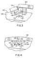
- the cutting mat 120 is wrapped about the rotary anvil 100.
- the first locking member 132 is inserted into the channel 106 of the rotary anvil 100.
- the foot 136 is not placed directly against the floor of the channel 106. Rather, the heel of the foot 136 is lowered into the channel 106, and the foot 136 is angled upward towards the uppermost extent of the channel 106 opposite the heel.
- the cutting mat 120 is axially positioned on the rotary anvil 100 such that the pin receptacle 140 is generally aligned with the pin 112.
- the second locking member 134 is also aligned generally over the channel 106.
- the first and second locking members 132, 134 are seated into the channel 106 generally concomitantly. It should be observed that in the particular embodiment described with reference to Fig. 3 , the pin 112 should preferably extend from the channel 106 no more than the height of the foot 136. This is because the second locking member 134 rests over the foot 136 of the first locking member 132 when the cutting mat 120 is installed on the anvil.
- the foot 136 when the first and second locking members 132, 134 are properly seated in the channel 106, the foot 136 rests on the floor of the channel 106 and need not occupy the entire width of the channel 106.
- the foot 136 has a length that is slightly less than the channel width.
- the pin receptacle 140 of the foot 136 is seated down over top of the pin 112.
- the first and second faces 138, 148 abut in mating relationship such that the locking projection 150 is received by the locking recess 146.
- the posts 152 are seated down into the slots 142.
- the cutting mat 120 is releasably secured to the rotary anvil 100 by frictional forces.
- the pin 112 may be thought of as providing a physical link to the foot 136 of the first locking member 132.
- the second locking member 134 is held within the channel 106 by contact with the first locking member 132.
- This arrangement ensures that the ends of the cutting mat 120 are secured to the rotary anvil 100, and are prevented from lifting or otherwise moving radially from the rotary anvil 100.
- the engagement of the pin 112 by the pin receptacle 140, the contoured surface profile of the first and second faces 138, 148, and the fitting of the posts 152 into the slots 142 all serve to prevent lateral (axial) shifting, skewing or other movement of the cutting mat 120. It shall be observed that the posts 152 and corresponding slots 142 may not be necessary depending upon the ability of the contour of the first and second faces 138, 148 and the pin 112 and pin receptacle 140 to provide sufficient lateral stability.
- the cutting mat 120 may be removed using any number of means.
- a standard screwdriver or specially designed tool may be inserted between the cutting mat 120 and the channel 106.
- the first and second locking members 132, 134 of the cutting mat 120 will come out of the channel.
- the lockup device 162 comprises a base 164, a sidewall 166 that projects from the base 164 disposed along an edge thereof, and a locking wedge 168 that projects from the base 164, extending generally parallel to the sidewall 166.
- the locking wedge 168 includes a leg portion 170 extending from the base 164 substantially normal thereto.
- First and second locking surfaces 172, 174 extend outwardly from opposite sides of the leg portion 170.
- First and second guide surfaces 176, 178 extend from their respective first and second locking surfaces 172, 174 and join together defining a substantially inverted "V" shape.
- the lockup device 162 is preferably constructed from a metal such as aluminum, however other suitable materials may be used such as plastics or composite materials.
- the lockup device 162 includes a pin receptacle 180 that is dimensioned to position over a pin projecting from the channel of a rotary anvil as described more fully herein.
- the pin receptacle may be formed for example, either as a cavity in a bottom surface of the base 164, as a cut-out portion in the lockup device 162, or as a through aperture. As shown, the pin receptacle is a through aperture that extends through the base 164 and locking wedge 168.
- the lockup device 162 further optionally includes one or more slots 182 therein. The slots 182 are illustrated adjacent to an axial edge of the base 164, but may be positioned anywhere on the lockup device 164.
- the slots 182 are shown extending entirely through the base 164, the slots 182 may be formed as cavities or cut out portions.
- the lockup device 162 may further include any of the features described in U.S. Patent No. 6,698,326 , entitled "LOCK-UP SYSTEM FOR CUTTING MAT.”
- the cutting mat 184 suitable for use with the lockup device 162 is illustrated.
- the cutting mat 184 is similar to the cutting mat 120 discussed above with reference to Figs. 1-4 differing, for example, in the configuration of the locking members. As such, like structure is represented by like reference numbers.
- the cutting mat 184 comprises a generally elongate body 122 and includes opposing and complementary first and second axial edges 124, 126.
- the first locking member 132 includes a first aligning surface 186 oriented such that when the first locking member 132 engages the lockup device 162, the first aligning surface 186 engages the first guide surface 176 of the locking wedge 168 to direct and guide the first locking member 132 into an appropriate locked position.
- the first locking member 132 also includes a first locking recess 188 extending axially therealong such that when the first locking member 132 is in the appropriate locked position with the lockup device 162, the first locking surface 172 and first guide surface 176 of the locking wedge 168 engage the first locking recess 188. If the lockup device 162 includes slots 182, then the first locking member 132 may include corresponding posts 190 projecting therefrom.
- the second locking member 134 includes a second aligning surface 192 oriented such that when the second locking member 134 is being snap fitted or otherwise inserted into the lockup device 162, the second aligning surface 192 engages the second guide surface 178 of the locking wedge 168 to direct and guide the second locking member 134 into a locking area defined between the sidewall 166 and the locking wedge 168.
- the second locking member 134 also includes a second locking recess 194 extending axially along therealong. When the second locking member 134 is appropriately positioned between the sidewall 166 and the locking wedge 168, the second locking surface 176 and second guide surface 178 of the locking wedge 168 engage the second locking recess 194.
- At least a portion of the first face 138 of the first locking member 132 is generally nonlinear.
- the first face 138 follows the pattern of the nonlinear first axial edge 124 thus defining a contoured surface profile in a first portion of the first face 138 defined generally between the first axial edge 124 and the first locking recess 188.
- a second portion of the first face 138 generally including the first locking recess 188 and first aligning surface 186 is generally linear in the axial direction so as to coincide with the lockup device 162.
- the second face 148 of the second locking member 134 is generally nonlinear and follows the pattern of the nonlinear second axial edge 126 thus defining a contoured surface profile in a first portion of the second face 148 defined generally between the second axial edge 126 and the second locking recess 194.
- a second portion of the second face 148 generally including the second locking recess 194 and second aligning surface 192 is generally linear in the axial direction so as to coincide with the lockup device 162.
- FIG. 7 One process for installing the cutting mat 184 onto a rotary anvil 100 is shown in Figs. 7 and 8 .
- the lockup device 162 is fit into the channel 106 of the rotary anvil 100 such that the base 164 of the lockup device 162 rests on the floor of the channel 106, and the sidewall 166 lies juxtaposed with a wall of the channel 106.
- the cutting mat 184 is partially installed on the lockup device 162 by press fitting or snap fitting the second locking member 134 into the locking area between the sidewall 166 and the locking wedge 168. This may be accomplished either before or after installing the lockup device 162 into the channel 106 of the rotary anvil 100.
- the pin 112 in the channel 106 suitably aligns over the pin receptacle 180. Because the cutting mat 184 is frictionally held to the rotary anvil 100, the width of the base 164 of the lockup device 162 need not form an interference or compressive fit with the width of the channel 106.
- the first locking member 132 is inserted into the channel 106 between the locking wedge 168 of the lockup device 162 and a sidewall of the channel 106.
- the sidewall 166 and locking wedge 168 of the lockup device 162 maintain a secure hold on the second locking member 134 of the cutting mat 184. This allows the lockup device 162 to release from the channel 106 while still attached to the cutting mat 184.
- first locking member 132 is generally thicker than the second locking member 134 to provide a large surface to snap into place while the cutting mat 184 is under pressure from being wrapped around the rotary anvil 100. Also, the cutting mat 184 and lockup device 162 are securely held to the rotary anvil 100 by the combination of frictional forces derived from fitting the lockup device 162 into the channel 106, from the engagement of the pin 112 with the pin receptacle 180, and from the frictional forces of the first and second locking members 132, 134.
- the pin 112 creates a physical link between a properly installed lockup and the cylinder 100 to provide an interconnection therebetween.
- the present invention enjoys the speed of installation and quick cutting mat changeover of a boltless design.
- the physical link created by the pin 112 can provide improved holding of the cutting mat to the cylinder 100 for example, during use where the edges of the channel walls are beveled due to wear or modification.
- several cutting mats may be axially aligned on the rotary anvil 100. This is best illustrated in Fig. 1 of U.S. Patent No. 6,629,482B2 .
- a user may simply release the worn cutting mat 120 from the channel 106 of the rotary anvil, and replace or rotate the cutting mat 184 and lockup device 162 end for end, and reposition it back in place without disturbing the remainder of the cutting mats 114.
- nonlinear seams created when cutting mats according to various embodiments of the present invention are used on a rotary anvil may provide increased cutting mat stability.
- the nonlinear axial edges tend to prevent lateral slippage (movement of the cutting mat in the axial direction).
- the nonlinear seams also allow the cutting mat 120 to align more easily on the rotary anvil, such as with adjacent cutting mats.
- each pin 112 is provided, one on each of the outermost edges of the anvil 100.
- a first cutting mat is installed over the first pin and a second cutting mat is installed over the second pin.
- Cutting mats installed between the pins 112 need not necessarily be provided with pins of their own because the outer most cutting mats will provide sufficient lateral stability to support the inner cutting mats.
- each cutting mat installed on the anvil 100 may include a pin 112.
Landscapes
- Life Sciences & Earth Sciences (AREA)
- Forests & Forestry (AREA)
- Engineering & Computer Science (AREA)
- Mechanical Engineering (AREA)
- Perforating, Stamping-Out Or Severing By Means Other Than Cutting (AREA)
- Details Of Cutting Devices (AREA)
Claims (19)
- Schneidmatte (184) für einen Drehamboss (100) und Schneidmatten-Verschlussvorrichtung (162):wobei die genannte Matte (184) einen allgemein langgestreckten Körper (122) umfasst und einen ersten und einen zweiten axialen Rand (124, 126) umfasst, die einander gegenüberliegenden und komplementär sind;einen ersten Endabschnitt (128) nah bei dem genannten ersten axialen Rand (124) mit einem ersten Verschlussglied (132), umfassend eine erste Stirnfläche (138), und einen zweiten Endabschnitt (130) nah bei dem genannten zweiten axialen Rand (126) mit einem zweiten Verschlussglied (134), umfassend eine zweite Stirnfläche (148) die allgemein komplementär zur genannten ersten Stirnfläche ist;und wobei die genannte Verschlussvorrichtung (162) Folgendes umfasst:eine Basis (164) mit einem ersten und einem zweiten axialen Rand;eine Seitenwand (166), die von dem genannten ersten axialen Rand der genannten Basis vorsteht; undeinen Verriegelungskeil (168), der von der genannten Basis vorsteht und einen ersten Verriegelungsbereich zwischen der genannten Seitenwand und dem genannten Verriegelungskeil und einen zweiten Verriegelungsbereich zwischen dem genannten Verriegelungskeil und dem genannten zweiten axialen Rand der genannten Basis definiert; undwobei die Verschlussvorrichtung (162) in eine Nut (106) des genannten Drehambosses (100) installierbar ist und die genannte Schneidmatte (184) in die genannte Verschlussvorrichtung (162) installierbar ist, so dass das genannte erste Verriegelungsglied (132) von dem genannten Verriegelungsbereich aufgenommen wird, das genannte zweite Verriegelungsglied (134) von dem genannten zweiten Verriegelungsbereich aufgenommen wird, wobei die genannte erste und die genannte zweite Stirnfläche in zusammenpassender Beziehung aneinander stoßen, unddadurch gekennzeichnet, dassdie Basis (164) der Verschlussvorrichtung (162) eine Stiftaufnahme (180) umfasst, die dazu bemessen ist, einen von der genannten Nut (106) des genannten Drehambosses (100) vorstehenden Stift (112) aufzunehmen,wobei die genannte Verschlussvorrichtung (162) durch Reibungskräfte, die durch das Aufnehmen des genannten Stifts (112) der genannten Nut durch die genannte Verschlussvorrichtungs-Stiftaufnahme (180) definiert werden, lösbar an dem genannten Drehamboss (100) befestigt ist, und die genannte Schneidmatte (184) durch reibendes Halten des genannten ersten Verriegelungsglieds (132) der genannten Schneidmatte in dem genannten ersten Verriegelungsbereich und reibendes Halten des genannten zweiten Verriegelungsglieds (134) der genannten Schneidmatte reibend in dem genannten zweiten Verriegelungsbereich zwischen einer Wand der genannten Nut und dem genannten Verriegelungskeil (168) reibend an der genannten Verschlussvorrichtung gehalten wird, so dass das genannte zweite Verriegelungsglied (134) mindestens teilweise gegen eine Wand der genannten Nut drückt; undder erste und der zweite einander gegenüberliegende axiale Rand (124, 126) der Matte (184) und mindestens ein Abschnitt der ersten und der zweiten Stirnfläche (138, 148) der einander gegenüberliegenden Verriegelungsglieder (132, 134) in einer Axialrichtung eine nichtlineare Naht dazwischen definieren.
- Schneidmatte und Verschlussvorrichtung nach Anspruch 1, wobei die genannte Stiftaufnahme (180) in der genannten Basis der genannten Verschlussvorrichtung einen in einer Unterseite der genannten Basis (164) gebildeten Hohlraum umfasst.
- Schneidmatte und Verschlussvorrichtung nach Anspruch 1, wobei die genannte Stiftaufnahme (180) in der genannten Basis (164) der genannten Verschlussvorrichtung (162) eine durchgehende Öffnung in der genannten Basis umfasst, die einen allgemein dem Querschnitt des genannten Stifts (112) entsprechenden Querschnitt aufweist.
- Schneidmatte und Verschlussvorrichtung nach Anspruch 1, wobei die genannte Basis (164) der genannten Verschlussvorrichtung (162) weiter einen Schlitz (182) umfasst und das genannte zweite Verriegelungsglied (134) einen davon vorstehenden Zapfen (190) umfasst, wobei der genannte Schlitz und der genannte Zapfen derart orientiert sind, dass wenn die genannte Schneidmatte und die genannte Verschlussvorrichtung in der genannten Nut (106) des genannten Drehambosses (100) installiert sind, der genannte Zapfen in dem genannten Schlitz einrastet.
- Schneidmatte (184) und Verschlussvorrichtung (162) nach Anspruch 4, wobei sich der genannte Schlitz (182) von dem genannten zweiten axialen Rand der genannten Basis (164) der genannten Verschlussvorrichtung nach innen erstreckt.
- Schneidmatte und Verschlussvorrichtung nach Anspruch 4, wobei sich der genannte Schlitz (182) vollständig durch die genannte Basis (164) erstreckt.
- Schneidmatte und Verschlussvorrichtung nach Anspruch 1, wobei die genannte Basis (164) der genannten Verschlussvorrichtung weiter eine Vielzahl von Schlitzen (182) umfasst und das genannte zweite Verriegelungsglied (134) eine entsprechende Vielzahl von davon vorstehenden Zapfen (190) umfasst, wobei die genannte Vielzahl von Schlitzen und die genannte Vielzahl von Zapfen derart orientiert sind, dass wenn die genannte Schneidmatte und die genannte Verschlussvorrichtung in der genannten Nut (106) des genannten Drehambosses (100) installiert sind, jeder der genannten Vielzahl von Zapfen in einem Entsprechenden der genannten Vielzahl von Schlitzen einrastet.
- Schneidmatte und Verschlussvorrichtung nach Anspruch 1, wobei die genannte Basis (164) der genannten Verschlussvorrichtung eine Breite aufweist, die geringer ist als die Breite der genannten Nut (106).
- Schneidmatte und Verschlussvorrichtung nach Anspruch 1, weiter umfassend einen ersten Schlitz (182), der sich mindestens teilweise durch die genannte Basis (164) der genannten Verschlussvorrichtung (162) erstreckt.
- Schneidmatte und Verschlussvorrichtung nach Anspruch 9, wobei das genannte zweite Verriegelungsglied (134) einen ersten Zapfen (190) umfasst, der in dem genannten ersten Schlitz (182) der genannten Verschlussvorrichtung einrastet.
- Schneidmatte (184) und Verschlussvorrichtung (162) nach Anspruch 9, wobei der genannte erste Schlitz (182) in der genannten Verschlussvorrichtung außerhalb des genannten zweiten axialen Rands der genannten Basis (164) ausgespart ist.
- Schneidmatte (184) und Verschlussvorrichtung (162) nach Anspruch 9, wobei die genannte Stiftaufnahme (180) ein Durchgangsloch in der genannten Basis (164) der genannten Verschlussvorrichtung umfasst.
- Schneidmatte und Verschlussvorrichtung nach Anspruch 9, wobei die genannte Stiftaufnahme (180) einen in einer Unterseite der genannten Basis (164) der genannten Verschlussvorrichtung gebildeten Hohlraum umfasst.
- Schneidmatte (184) und Verschlussvorrichtung (162) nach Anspruch 9, wobei die genannte Basis (164) der genannten Verschlussvorrichtung mindestens einen zusätzlichen Schlitz (182) umfasst und das genannte zweite Verriegelungsglied (134) eine entsprechende Zahl zusätzlicher Zapfen (190) umfasst, so dass wenn die genannte Verschlussvorrichtung und das genannte erste und das genannte zweite Verriegelungsglied in der genannten Nut (106) positioniert sind, jeder Zapfen in einem zugehörigen Schlitz einrastet.
- Verfahren zum Installieren einer Schneidmatte (184) und einer Verschlussvorrichtung (162) auf einen Drehamboss (100), das Folgendes umfasst:Bereitstellen einer Schneidmatte (184), umfassend einen Körper (122) mit einem ersten und einem zweiten axialen Ende (128, 130), einem ersten Verriegelungsglied (132), umfassend eine erste Stirnfläche (138), wobei das erste Verriegelungsglied von dem genannten ersten axialen Ende (128) vorsteht, und einem zweiten Verriegelungsglied (134), umfassend eine zweite Stirnfläche (148), wobei das zweite Verriegelungsglied von dem genannten zweiten axialen Ende (130) vorsteht;Bereitstellen einer Schneidmatten-Verschlussvorrichtung (162), umfassend:einen Basisabschnitt (164) mit einem ersten und einem zweiten axialen Rand (124, 126) und einem ersten und einem zweiten transversalen Rand; wobei eine Seitenwand (166) von dem genannten ersten axialen Rand der genannten Basis vorsteht; wobei ein Verriegelungskeil (168) von der genannten Basis vorsteht;Installieren des genannten ersten Verriegelungsglieds der genannten Schneidmatte zwischen der genannten Seitenwand und dem genannten Verriegelungsvorsprung der genannten Verschlussvorrichtung; gekennzeichnet durchBereitstellen einer nichtlinearen Naht in einer axialen Richtung zwischen dem ersten und dem zweiten einander gegenüberliegenden axialen Rand (124, 126) der Matte (184) und mindestens einem Abschnitt der ersten und der zweiten Stirnfläche (138, 148);Bereitstellen einer auf dem genannten Basisabschnitt positionierten Stiftaufnahme (180);Installieren eines Stifts (112) in eine Nut (106), die sich axial entlang der Oberfläche des genannten Drehambosses erstreckt;Installieren der genannten Verschlussvorrichtung (162) in der genannten Nut (106), so dass die genannte Stiftaufnahme (180) über dem genannten Stift (112) positioniert ist;Wickeln des genannten Körpers der genannten Schneidmatte (120) um den genannten Amboss (100); undPositionieren des genannten Verriegelungsglieds (134) der genannten Schneidmatte in der genannten Nut (106) angrenzend an den genannten Verriegelungskeil (168).
- Verfahren nach Anspruch 15, wobei das genannte erste Verriegelungsglied (132) zwischen der genannten Seitenwand (166) und dem genannten Verriegelungskeil (168) installiert wird, bevor die genannte Verschlussvorrichtung in der genannten Nut (106) des genannten Drehambosses (100) installiert wird.
- Verfahren nach Anspruch 15, weiter umfassend das Bereitstellen mindestens eines Schlitzes (182) in der genannten Basis (164) der genannten Verschlussvorrichtung (162) und entsprechendes Bereitstellen von mindestens einem Zapfen (190) in dem genannten zweiten Verriegelungsglied (134), so dass wenn die genannten Schneidmatte (120) auf dem genannten Drehamboss (100) installiert wird, jeder Zapfen von einem zugehörigen Schlitz aufgenommen wird.
- Verfahren nach Anspruch 15, das weiter Folgendes umfasst:Installieren eines zweiten Stifts (112) in die genannte Nut (106), der axial von dem genannten ersten Stift beabstandet ist;Bereitstellen einer ersten und einer zweiten Schneidmatten-Verschlussvorrichtung, wobei die Vorrichtungen jeweils Folgendes umfassen:einen Basisabschnitt (164) mit einem ersten und einem zweiten axialen Rand und einem ersten und einem zweiten transversalen Rand;eine Seitenwand (166), die von dem genannten ersten axialen Rand der genannten Basis vorsteht;einen Verriegelungskeil (168), der von der genannten Basis vorsteht; undeine auf dem genannten Basisabschnitt positionierten Stiftaufnahme (180);Bereitstellen einer ersten und einer zweiten Schneidmatte, wobei die Matten jeweils einen Körper mit einem ersten und einem zweiten axialen Ende umfassen, wobei ein erstes Verriegelungsglied (132) von dem genannten ersten axialen Ende vorsteht, und wobei ein zweites Verriegelungsglied (134) von dem genannten zweiten axialen Ende vorsteht;Installieren des genannten ersten Verriegelungsglieds der genannten ersten Schneidmatte zwischen der genannten Seitenwand und dem genannten Verriegelungsvorsprung der genannten ersten Verschlussvorrichtung;Installieren der genannten ersten Verschlussvorrichtung in der genannten Nut (106), so dass die genannte Stiftaufnahme (180) der genannten ersten Verschlussvorrichtung über dem genannten ersten Stift (112) positioniert ist;Wickeln des genannten Körpers der genannten ersten Schneidmatte um den genannten Amboss;Positionieren des genannten zweiten Verriegelungsglieds der genannten ersten Schneidmatte in der genannten Nut (106) angrenzend an den genannten ersten Verriegelungskeil;Installieren des genannten ersten Verriegelungsglieds der genannten zweiten Schneidmatte zwischen der genannten Seitenwand (166) und dem genannten Verriegelungsvorsprung der genannten zweiten Verschlussvorrichtung;Installieren der genannten zweiten Verschlussvorrichtung in der genannten Nut (106), so dass die genannte Stiftaufnahme (180) der genannten zweitenVerschlussvorrichtung über dem genannten zweiten Stift (112) positioniert ist; Wickeln des genannten Körpers der genannten zweiten Schneidmatte um den genannten Amboss; undPositionieren des genannten zweiten Verriegelungsglieds der genannten zweiten Schneidmatte in der genannten Nut angrenzend an den genannten zweiten Verriegelungskeil.
- Verfahren nach Anspruch 18, weiter umfassend das Installieren von einer oder mehreren Schneidmatten auf dem genannten Drehamboss zwischen der genannten ersten und der genannten zweiten Schneidmatte.
Priority Applications (1)
| Application Number | Priority Date | Filing Date | Title |
|---|---|---|---|
| EP20090177125 EP2156929B1 (de) | 2003-05-21 | 2004-04-02 | Gummituch mit verriegelungselementen und nicht geradlinigen kanten |
Applications Claiming Priority (2)
| Application Number | Priority Date | Filing Date | Title |
|---|---|---|---|
| US10/442,700 US7007581B2 (en) | 2003-05-21 | 2003-05-21 | Cutting mat for a rotary anvil |
| PCT/US2004/010215 WO2004106019A1 (en) | 2003-05-21 | 2004-04-02 | Cutting mat and method of installing a cutting mat on a rotary anvil |
Related Child Applications (1)
| Application Number | Title | Priority Date | Filing Date |
|---|---|---|---|
| EP20090177125 Division-Into EP2156929B1 (de) | 2003-05-21 | 2004-04-02 | Gummituch mit verriegelungselementen und nicht geradlinigen kanten |
Publications (2)
| Publication Number | Publication Date |
|---|---|
| EP1628809A1 EP1628809A1 (de) | 2006-03-01 |
| EP1628809B1 true EP1628809B1 (de) | 2012-09-05 |
Family
ID=33450262
Family Applications (2)
| Application Number | Title | Priority Date | Filing Date |
|---|---|---|---|
| EP20090177125 Expired - Lifetime EP2156929B1 (de) | 2003-05-21 | 2004-04-02 | Gummituch mit verriegelungselementen und nicht geradlinigen kanten |
| EP20040785591 Expired - Lifetime EP1628809B1 (de) | 2003-05-21 | 2004-04-02 | Schneidmatte und verfahren zur installation einer schneidmatte auf einem drehamboss |
Family Applications Before (1)
| Application Number | Title | Priority Date | Filing Date |
|---|---|---|---|
| EP20090177125 Expired - Lifetime EP2156929B1 (de) | 2003-05-21 | 2004-04-02 | Gummituch mit verriegelungselementen und nicht geradlinigen kanten |
Country Status (4)
| Country | Link |
|---|---|
| US (2) | US7007581B2 (de) |
| EP (2) | EP2156929B1 (de) |
| ES (2) | ES2393553T3 (de) |
| WO (1) | WO2004106019A1 (de) |
Families Citing this family (5)
| Publication number | Priority date | Publication date | Assignee | Title |
|---|---|---|---|---|
| JP4612899B2 (ja) * | 2006-02-17 | 2011-01-12 | キヤノン株式会社 | シート搬送ローラ、シート搬送装置、及び画像形成装置 |
| JP6830491B2 (ja) | 2015-09-23 | 2021-02-17 | チンタオ ボー ファ テクノロジー カンパニー リミテッド | カッティングマットおよびその作製方法 |
| PT3421198T (pt) * | 2016-06-10 | 2019-12-10 | Rodicut Ind S A U | Manta de cilindro contramatriz de máquina de corte e vinco e processo de fabrico de mantas |
| US12528221B2 (en) * | 2020-12-10 | 2026-01-20 | Dicar Inc. | Die machine and drive member installed thereon |
| US11642807B2 (en) * | 2021-04-08 | 2023-05-09 | Excelsior Inc. | Support for cutting a linear product |
Family Cites Families (44)
| Publication number | Priority date | Publication date | Assignee | Title |
|---|---|---|---|---|
| US229513A (en) * | 1880-07-06 | Wood-grinder for making paper-pulp | ||
| US1912069A (en) * | 1931-04-10 | 1933-05-30 | Titan Abrasives Co Inc | Grinding wheel |
| US2712205A (en) * | 1952-06-20 | 1955-07-05 | Crucible Steel Company | Abrading roll |
| US3045323A (en) * | 1960-02-08 | 1962-07-24 | Jr John D Willingham | Combination roll and attaching device for ironer rolls |
| US3270607A (en) * | 1963-06-25 | 1966-09-06 | Oesterreicher Ignaz | Holder for a stick for a guillotine-type paper-cutter machine |
| US3522754A (en) * | 1967-08-14 | 1970-08-04 | Centenary Central | Reinforced freewheeling resilient cover for rotary die-cutting anvil |
| US3577822A (en) * | 1969-04-16 | 1971-05-04 | Centenary Central | Removable freewheeling resilient cover for rotary anvil |
| USRE28581E (en) * | 1970-11-10 | 1975-10-28 | Roller-type press | |
| US3765329A (en) * | 1971-09-28 | 1973-10-16 | A Kirkpatrick | Cylinder cover fastening devices |
| US3885486A (en) * | 1971-09-28 | 1975-05-27 | Alan D Kirkpatrick | Cylinder cover fastening devices |
| US3739675A (en) * | 1972-02-07 | 1973-06-19 | Dayco Corp | Rotary anvil construction |
| US3880037A (en) * | 1974-01-07 | 1975-04-29 | Dayco Corp | Rotary anvil construction |
| US3882750A (en) * | 1974-07-22 | 1975-05-13 | Dayco Corp | Rotary anvil construction |
| US4075918A (en) * | 1974-10-17 | 1978-02-28 | L. E. Sauer Machine Company | Rotary anvil cover |
| US4031600A (en) * | 1975-11-10 | 1977-06-28 | The Fluorocarbon Company | Attachment means for a machinery drum cover |
| JPS5314839A (en) * | 1976-07-20 | 1978-02-09 | Nitto Boseki Co Ltd | Cutting apparatus for long fiber |
| US4073207A (en) * | 1976-12-22 | 1978-02-14 | Robud Co. | Lock for rotary die cutting blanket |
| US4191076A (en) * | 1978-10-23 | 1980-03-04 | Dayco Corporation | Rotary anvil construction |
| US4240312A (en) * | 1979-05-15 | 1980-12-23 | The Ward Machinery Company | Apparatus for improving wear life of rotary die cutter anvil covers |
| US4240192A (en) * | 1979-06-22 | 1980-12-23 | Dayco Corporation | Tool for and method of removing a die-cutting mat from a rotary anvil |
| US4337700A (en) * | 1980-05-30 | 1982-07-06 | Pathfinder Graphic Associates, Inc. | Blanket cylinder construction for printing press |
| US4378737A (en) * | 1981-06-01 | 1983-04-05 | Robud Company | Roller apparatus with replacement blanket |
| JPS5941807B2 (ja) | 1982-05-10 | 1984-10-09 | 株式会社黒木工業所 | 熱間金属片移送用ロ−ル |
| US4791846A (en) * | 1987-10-23 | 1988-12-20 | Robud Company | Oscillating free wheeling resilient cover for rotary die-cutting anvil |
| US4848204A (en) * | 1988-06-22 | 1989-07-18 | Corfine Inc. | Die cutter blanket |
| US4982639A (en) * | 1988-10-31 | 1991-01-08 | Robud Company | Die cutting anvil system |
| US4867024A (en) * | 1989-02-10 | 1989-09-19 | Tdw Delaware, Inc. | Locking rotary die cutting cover |
| US5078535A (en) * | 1989-03-02 | 1992-01-07 | Robud Co. | Locking means |
| US5219352A (en) * | 1989-07-03 | 1993-06-15 | Zimmer, Inc. | Skin graft preparation apparatus |
| US5076128A (en) * | 1990-04-26 | 1991-12-31 | Connor Barry J O | Die cutter blanket |
| GB9407877D0 (en) | 1994-04-21 | 1994-06-15 | Scapa Group Plc | Die cutting blanket |
| US5758560A (en) * | 1995-01-05 | 1998-06-02 | C.U.E. Inc. | Anvil cover latch assembly |
| US5720212A (en) * | 1995-03-22 | 1998-02-24 | Robud | Locking arrangement for die cutter blanket |
| US5906149A (en) * | 1995-11-30 | 1999-05-25 | Montenegro Criado; Manuel | Anvil for rotary slotting and cutting machines |
| US6073530A (en) * | 1996-05-06 | 2000-06-13 | City Stamp Works, Inc. | Rule guard |
| US5916346A (en) * | 1997-10-14 | 1999-06-29 | Robud | Die cutter blanket |
| US6116135A (en) * | 1998-01-26 | 2000-09-12 | Wagner; Kenneth | Unitary resilient cover for rotary anvil |
| US6135002A (en) * | 1998-04-27 | 2000-10-24 | Neal; Kenneth Ray | Die cutter blanket and bearing and method of arranging the blanket and bearing on an anvil |
| US6435069B1 (en) * | 1999-11-23 | 2002-08-20 | Iam Corporation | Rotary die cutting cover |
| US6539629B2 (en) * | 2001-01-26 | 2003-04-01 | Great Computer Corp. | Roller shaft on computer character-cutting device and method to manufacture the same |
| US6698326B2 (en) * | 2001-04-23 | 2004-03-02 | Day International, Inc. | Lock-up system for cutting mat |
| US6629482B2 (en) * | 2001-06-15 | 2003-10-07 | Day International, Inc. | Boltless cutting mat lock up |
| US6668694B2 (en) * | 2001-08-29 | 2003-12-30 | Robud, A Florida Partnership | Die cutter blanket locking arrangement |
| US6820529B2 (en) * | 2002-06-03 | 2004-11-23 | Day International, Inc. | Cutting mat |
-
2003
- 2003-05-21 US US10/442,700 patent/US7007581B2/en not_active Expired - Lifetime
-
2004
- 2004-04-02 EP EP20090177125 patent/EP2156929B1/de not_active Expired - Lifetime
- 2004-04-02 ES ES04785591T patent/ES2393553T3/es not_active Expired - Lifetime
- 2004-04-02 EP EP20040785591 patent/EP1628809B1/de not_active Expired - Lifetime
- 2004-04-02 WO PCT/US2004/010215 patent/WO2004106019A1/en not_active Ceased
- 2004-04-02 ES ES09177125T patent/ES2388705T3/es not_active Expired - Lifetime
-
2006
- 2006-01-09 US US11/328,346 patent/US8590436B2/en active Active
Also Published As
| Publication number | Publication date |
|---|---|
| HK1140984A1 (en) | 2010-10-29 |
| US7007581B2 (en) | 2006-03-07 |
| US8590436B2 (en) | 2013-11-26 |
| ES2388705T3 (es) | 2012-10-17 |
| US20040231479A1 (en) | 2004-11-25 |
| EP2156929A2 (de) | 2010-02-24 |
| EP2156929B1 (de) | 2012-06-20 |
| ES2393553T3 (es) | 2012-12-26 |
| US20060107807A1 (en) | 2006-05-25 |
| WO2004106019A1 (en) | 2004-12-09 |
| EP2156929A3 (de) | 2010-04-21 |
| EP1628809A1 (de) | 2006-03-01 |
Similar Documents
| Publication | Publication Date | Title |
|---|---|---|
| EP1509371B1 (de) | Gummituch | |
| EP1404496B1 (de) | Gummituch mit verriegelungselementen und nicht geradlinigen kanten | |
| US5078535A (en) | Locking means | |
| EP1628809B1 (de) | Schneidmatte und verfahren zur installation einer schneidmatte auf einem drehamboss | |
| HU213497B (en) | Cresing apparatus | |
| US6698326B2 (en) | Lock-up system for cutting mat | |
| HK1140984B (en) | Cutting mat having locking members and nonlinear edges | |
| FI85236B (fi) | Bandstaolsstansverktyg med ett elastiskt profilband. | |
| HK1093466B (en) | Cutting mat | |
| US6722246B2 (en) | Cylinder cover | |
| HK1067989B (en) | Cutting mat having locking members and nonlinear edges | |
| HK1058501B (en) | Lock-up system for cutting mat | |
| WO1997011823A1 (en) | Rotary die cutting machine |
Legal Events
| Date | Code | Title | Description |
|---|---|---|---|
| PUAI | Public reference made under article 153(3) epc to a published international application that has entered the european phase |
Free format text: ORIGINAL CODE: 0009012 |
|
| 17P | Request for examination filed |
Effective date: 20051221 |
|
| AK | Designated contracting states |
Kind code of ref document: A1 Designated state(s): DE ES FR GB IT |
|
| DAX | Request for extension of the european patent (deleted) | ||
| RBV | Designated contracting states (corrected) |
Designated state(s): DE ES FR GB IT |
|
| REG | Reference to a national code |
Ref country code: HK Ref legal event code: DE Ref document number: 1087380 Country of ref document: HK |
|
| GRAP | Despatch of communication of intention to grant a patent |
Free format text: ORIGINAL CODE: EPIDOSNIGR1 |
|
| GRAS | Grant fee paid |
Free format text: ORIGINAL CODE: EPIDOSNIGR3 |
|
| GRAA | (expected) grant |
Free format text: ORIGINAL CODE: 0009210 |
|
| AK | Designated contracting states |
Kind code of ref document: B1 Designated state(s): DE ES FR GB IT |
|
| REG | Reference to a national code |
Ref country code: GB Ref legal event code: FG4D |
|
| REG | Reference to a national code |
Ref country code: DE Ref legal event code: R096 Ref document number: 602004039225 Country of ref document: DE Effective date: 20121031 |
|
| REG | Reference to a national code |
Ref country code: ES Ref legal event code: FG2A Ref document number: 2393553 Country of ref document: ES Kind code of ref document: T3 Effective date: 20121226 |
|
| RAP2 | Party data changed (patent owner data changed or rights of a patent transferred) |
Owner name: DAY INTERNATIONAL, INC. |
|
| PLBE | No opposition filed within time limit |
Free format text: ORIGINAL CODE: 0009261 |
|
| STAA | Information on the status of an ep patent application or granted ep patent |
Free format text: STATUS: NO OPPOSITION FILED WITHIN TIME LIMIT |
|
| 26N | No opposition filed |
Effective date: 20130606 |
|
| REG | Reference to a national code |
Ref country code: DE Ref legal event code: R097 Ref document number: 602004039225 Country of ref document: DE Effective date: 20130606 |
|
| REG | Reference to a national code |
Ref country code: HK Ref legal event code: WD Ref document number: 1087380 Country of ref document: HK |
|
| PGFP | Annual fee paid to national office [announced via postgrant information from national office to epo] |
Ref country code: GB Payment date: 20140428 Year of fee payment: 11 |
|
| PGFP | Annual fee paid to national office [announced via postgrant information from national office to epo] |
Ref country code: FR Payment date: 20140417 Year of fee payment: 11 Ref country code: ES Payment date: 20140428 Year of fee payment: 11 Ref country code: IT Payment date: 20140424 Year of fee payment: 11 Ref country code: DE Payment date: 20140429 Year of fee payment: 11 |
|
| REG | Reference to a national code |
Ref country code: DE Ref legal event code: R119 Ref document number: 602004039225 Country of ref document: DE |
|
| GBPC | Gb: european patent ceased through non-payment of renewal fee |
Effective date: 20150402 |
|
| PG25 | Lapsed in a contracting state [announced via postgrant information from national office to epo] |
Ref country code: DE Free format text: LAPSE BECAUSE OF NON-PAYMENT OF DUE FEES Effective date: 20151103 Ref country code: GB Free format text: LAPSE BECAUSE OF NON-PAYMENT OF DUE FEES Effective date: 20150402 Ref country code: IT Free format text: LAPSE BECAUSE OF NON-PAYMENT OF DUE FEES Effective date: 20150402 |
|
| REG | Reference to a national code |
Ref country code: FR Ref legal event code: ST Effective date: 20151231 |
|
| PG25 | Lapsed in a contracting state [announced via postgrant information from national office to epo] |
Ref country code: FR Free format text: LAPSE BECAUSE OF NON-PAYMENT OF DUE FEES Effective date: 20150430 |
|
| REG | Reference to a national code |
Ref country code: ES Ref legal event code: FD2A Effective date: 20160526 |
|
| PG25 | Lapsed in a contracting state [announced via postgrant information from national office to epo] |
Ref country code: ES Free format text: LAPSE BECAUSE OF NON-PAYMENT OF DUE FEES Effective date: 20150403 |