EP1629147B1 - Tambour pour machine a laver ou seche linge - Google Patents
Tambour pour machine a laver ou seche linge Download PDFInfo
- Publication number
- EP1629147B1 EP1629147B1 EP04736016A EP04736016A EP1629147B1 EP 1629147 B1 EP1629147 B1 EP 1629147B1 EP 04736016 A EP04736016 A EP 04736016A EP 04736016 A EP04736016 A EP 04736016A EP 1629147 B1 EP1629147 B1 EP 1629147B1
- Authority
- EP
- European Patent Office
- Prior art keywords
- drum
- body part
- metal
- reduced
- cylinder
- Prior art date
- Legal status (The legal status is an assumption and is not a legal conclusion. Google has not performed a legal analysis and makes no representation as to the accuracy of the status listed.)
- Revoked
Links
- 229910052751 metal Inorganic materials 0.000 claims description 53
- 239000002184 metal Substances 0.000 claims description 53
- 238000003825 pressing Methods 0.000 claims description 22
- 239000011324 bead Substances 0.000 claims description 19
- 229910000831 Steel Inorganic materials 0.000 claims description 16
- 239000010959 steel Substances 0.000 claims description 16
- 238000003466 welding Methods 0.000 claims description 14
- 238000005096 rolling process Methods 0.000 claims description 12
- HCHKCACWOHOZIP-UHFFFAOYSA-N Zinc Chemical group [Zn] HCHKCACWOHOZIP-UHFFFAOYSA-N 0.000 claims description 10
- 229910052725 zinc Inorganic materials 0.000 claims description 10
- 239000011701 zinc Substances 0.000 claims description 10
- 238000005728 strengthening Methods 0.000 claims description 8
- 239000010935 stainless steel Substances 0.000 claims description 6
- 229910001220 stainless steel Inorganic materials 0.000 claims description 6
- CCEKAJIANROZEO-UHFFFAOYSA-N sulfluramid Chemical compound CCNS(=O)(=O)C(F)(F)C(F)(F)C(F)(F)C(F)(F)C(F)(F)C(F)(F)C(F)(F)C(F)(F)F CCEKAJIANROZEO-UHFFFAOYSA-N 0.000 claims description 4
- 229910001297 Zn alloy Inorganic materials 0.000 claims description 3
- 229910000680 Aluminized steel Inorganic materials 0.000 claims description 2
- HXFVOUUOTHJFPX-UHFFFAOYSA-N alumane;zinc Chemical compound [AlH3].[Zn] HXFVOUUOTHJFPX-UHFFFAOYSA-N 0.000 claims description 2
- 239000004411 aluminium Substances 0.000 claims description 2
- 229910052782 aluminium Inorganic materials 0.000 claims description 2
- XAGFODPZIPBFFR-UHFFFAOYSA-N aluminium Chemical compound [Al] XAGFODPZIPBFFR-UHFFFAOYSA-N 0.000 claims description 2
- 238000000034 method Methods 0.000 description 12
- 238000001035 drying Methods 0.000 description 8
- 238000004519 manufacturing process Methods 0.000 description 8
- 238000010586 diagram Methods 0.000 description 7
- 238000004891 communication Methods 0.000 description 5
- 230000008602 contraction Effects 0.000 description 4
- 230000009467 reduction Effects 0.000 description 4
- 238000005452 bending Methods 0.000 description 2
- 230000015572 biosynthetic process Effects 0.000 description 2
- 230000007797 corrosion Effects 0.000 description 2
- 238000005260 corrosion Methods 0.000 description 2
- 230000002349 favourable effect Effects 0.000 description 2
- 230000001771 impaired effect Effects 0.000 description 2
- 238000002156 mixing Methods 0.000 description 2
- 238000012986 modification Methods 0.000 description 2
- 230000004048 modification Effects 0.000 description 2
- 229910045601 alloy Inorganic materials 0.000 description 1
- 239000000956 alloy Substances 0.000 description 1
- 230000000994 depressogenic effect Effects 0.000 description 1
- 238000009792 diffusion process Methods 0.000 description 1
- 239000000428 dust Substances 0.000 description 1
- 238000002474 experimental method Methods 0.000 description 1
- 230000006872 improvement Effects 0.000 description 1
- 239000000463 material Substances 0.000 description 1
- 238000010422 painting Methods 0.000 description 1
- 230000008569 process Effects 0.000 description 1
- 230000003252 repetitive effect Effects 0.000 description 1
- 238000007789 sealing Methods 0.000 description 1
- XLYOFNOQVPJJNP-UHFFFAOYSA-N water Substances O XLYOFNOQVPJJNP-UHFFFAOYSA-N 0.000 description 1
- 238000004804 winding Methods 0.000 description 1
Images







Classifications
-
- B—PERFORMING OPERATIONS; TRANSPORTING
- B21—MECHANICAL METAL-WORKING WITHOUT ESSENTIALLY REMOVING MATERIAL; PUNCHING METAL
- B21D—WORKING OR PROCESSING OF SHEET METAL OR METAL TUBES, RODS OR PROFILES WITHOUT ESSENTIALLY REMOVING MATERIAL; PUNCHING METAL
- B21D51/00—Making hollow objects
- B21D51/16—Making hollow objects characterised by the use of the objects
- B21D51/18—Making hollow objects characterised by the use of the objects vessels, e.g. tubs, vats, tanks, sinks, or the like
-
- B—PERFORMING OPERATIONS; TRANSPORTING
- B21—MECHANICAL METAL-WORKING WITHOUT ESSENTIALLY REMOVING MATERIAL; PUNCHING METAL
- B21D—WORKING OR PROCESSING OF SHEET METAL OR METAL TUBES, RODS OR PROFILES WITHOUT ESSENTIALLY REMOVING MATERIAL; PUNCHING METAL
- B21D53/00—Making other particular articles
- B21D53/26—Making other particular articles wheels or the like
- B21D53/34—Making other particular articles wheels or the like brake drums
-
- D—TEXTILES; PAPER
- D06—TREATMENT OF TEXTILES OR THE LIKE; LAUNDERING; FLEXIBLE MATERIALS NOT OTHERWISE PROVIDED FOR
- D06F—LAUNDERING, DRYING, IRONING, PRESSING OR FOLDING TEXTILE ARTICLES
- D06F37/00—Details specific to washing machines covered by groups D06F21/00 - D06F25/00
- D06F37/02—Rotary receptacles, e.g. drums
-
- D—TEXTILES; PAPER
- D06—TREATMENT OF TEXTILES OR THE LIKE; LAUNDERING; FLEXIBLE MATERIALS NOT OTHERWISE PROVIDED FOR
- D06F—LAUNDERING, DRYING, IRONING, PRESSING OR FOLDING TEXTILE ARTICLES
- D06F37/00—Details specific to washing machines covered by groups D06F21/00 - D06F25/00
- D06F37/02—Rotary receptacles, e.g. drums
- D06F37/04—Rotary receptacles, e.g. drums adapted for rotation or oscillation about a horizontal or inclined axis
-
- D—TEXTILES; PAPER
- D06—TREATMENT OF TEXTILES OR THE LIKE; LAUNDERING; FLEXIBLE MATERIALS NOT OTHERWISE PROVIDED FOR
- D06F—LAUNDERING, DRYING, IRONING, PRESSING OR FOLDING TEXTILE ARTICLES
- D06F58/00—Domestic laundry dryers
- D06F58/02—Domestic laundry dryers having dryer drums rotating about a horizontal axis
- D06F58/04—Details
-
- D—TEXTILES; PAPER
- D06—TREATMENT OF TEXTILES OR THE LIKE; LAUNDERING; FLEXIBLE MATERIALS NOT OTHERWISE PROVIDED FOR
- D06F—LAUNDERING, DRYING, IRONING, PRESSING OR FOLDING TEXTILE ARTICLES
- D06F58/00—Domestic laundry dryers
- D06F58/20—General details of domestic laundry dryers
Definitions
- the present invention relates to drums for washers or dryers, and more particularly, to a drum which can prevent occurrence of noise and vibration.
- the dryer is an apparatus for drying a drying object, such as clothes introduced into a drum with hot air heated by an electric heater, a gas burner, or the like, of which demand keeps increasing, recently (e.g. see: document US-A-5127169 ).
- FIG. 1 illustrates a disassembled perspective view of a related art dryer.
- the related art drum 1 is provided inside of a cabinet (not shown) that forms an exterior of the dryer.
- the drum 1 is cylindrical with opened front and rear, having a belt groove 2 along an outside circumferential surface for winding a belt (not shown) connected to a motor or the like.
- the drum 1 has a chamber 5 for holding the drying object therein, with a plurality of lifts 6 each projected a length from an inside circumferential surface of the chamber 5, for lifting/dropping the drying object during rotation of the drum 1, to turn the drying object upside down, for fast drying of the drying object.
- the drum 1 is provided with a front supporter 7 and a rear supporter 9 to a front and a rear thereof, respectively.
- the front supporter 7 and the rear supporter 9 close as well as support the front and the rear of the chamber 5, respectively.
- the front supporter 7/the rear supporter 9 are provided with a plurality of rollers (not shown) in alignment with the front and the rear of the drum 1 for supporting the drum 1, respectively.
- the front supporter 7 has an opening 8 for making the chamber 5 in communication with an outside of the chamber 5.
- the opening 8 is opened/closed by a door, selectively.
- the rear supporter 9 is provided with a supply duct 12 in communication with the chamber 5 as a passage for supplying hot air to the chamber 5.
- the outlet assembly 13 There is an outlet assembly 13 at one side of the front supporter 7 under the opening 8 in the front supporter 7 as a passage for escaping of air from the chamber 5.
- the outlet assembly 13 has a filter 14 fitted thereto.
- the filter 14 removes foreign matters (for an example, thread wastes, or dust) from the air escaping from the chamber 5.
- the outlet assembly 13 is in communication with an exhaust duct 15, having the filter 14 positioned at an inlet thereof.
- the exhaust duct 15 is connected to a fan housing 18 for flow of air from the chamber 5 to the exhaust duct 15 and the fan housing 18 as a fan 17 in the fan housing 18 comes into operation.
- the fan 5 is a centrifugal fan for effective use of a space, but an axial fan is also acceptable.
- the fan housing 18 has one side in communication with the exhaust duct 15, and the other side connected to the exhaust pipe 19. According to this, air passed through the fan housing 18 is discharged to an outside through an exhaust pipe 19.
- the supply duct has an inlet in communication with a guide funnel 16.
- the guide funnel 16 has a form of a truncated cone for guiding the hot air produced by burning the gas toward the inlet of the supply duct.
- the gas burning device 20 is provided to the inlet of the guide funnel 16.
- the gas burning device 20 is provided with a valve, a mixing tube, and an igniter.
- the valve connected to a gas pipe, controls supply of gas.
- the mixing tube mixes the gas sprayed from the gas nozzle with the air, and the igniter ignites the mixed gas.
- the drum applied to the dryer is fabricating by the following process in the related art.
- thin metal plate of such as stainless steel is rolled into a cylinder and a seam thereof is welded.
- a diameter of a middle part of the cylindrical drum is expanded, leaving both ends as they are.
- the middle part of the drum is expanded as dies provided to an inside thereof press assigned areas of an inside circumferential surface of the drum, outwardly.
- beads are formed in the middle part of the expanded drum. That is, a plurality of thin grooves are form along an outside circumferential surface of the drum, for strengthening the drum. Also, front and rear edges of the drum are hemmed.
- the middle part of the drum is expanded by pressing the inside circumferential surface of the middle part of the drum with the dies. Therefore, after finishing fabrication of the drum, traces of the dies remain on the drum, resulting in a poor outer appearance. Also, as a circular shape of the drum is impaired, the drum fails to have uniform rotation inertia, to generate noise and vibration during rotating the drum.
- An object of the present invention designed to solve the foregoing problems is to provide a drum for a washer and a dryer, which can prevent vibration and noise from occurring.
- the object of the present invention can be achieved by providing a drum for a washer and a dryer including a cylindrical metal body part, reduced parts at opposite end parts of the body part, each having a diameter smaller than a diameter of the body part, and bent parts each having a folded edge of the reduced part.
- the reduced part includes the opposite end part of the body part having a diameter thereof reduced by pressing.
- the drum further includes a connection part between the body part and the reduced part having a diameter reduced, continuously.
- the cylindrical body is form by rolling metal sheet and butt welding a seam.
- the butt welding is made except predetermined lengths of opposite edges of the seam in a length direction for forming the bent parts.
- the metal cylinder has a thickness of 0.5. ⁇ 0.8mm. More preferably, the metal cylinder has a thickness of 0.55 ⁇ 0.7mm.
- a ratio of an inside diameter of the body part to the inside diameter of the reduced part is equal to, or greater than 0.9. More preferably, the ratio of an inside diameter of the body part to the inside diameter of the reduced part is 0.93 ⁇ 0.94.
- a difference of depths between an outside diameter of the body part adjacent to the reduced part and an outside diameter of the reduced part is below 25mm.
- the metal cylinder is zinc plated.
- the metal is stainless steel STS.
- the metal may be EGI (Electrolytic Zinc Coated Steel, SECC).
- the metal may be GI (Hot Dip Zinc Coated Steel, SGCC).
- the metal may be Galvanneld steel (steel-zinc Alloy coated steel wherein the alloy is made from the steel and zinc by diffusion owing to heat).
- the metal may be Galvalume GL (Aluminium-zinc Alloy coated steel).
- the metal may be Alstar (Hot Dip Aluminized steel).
- the metal may be Alcostar (Aluminium coated steel).
- the metal may be SFCH.
- the metal may be SGCH.
- SFCH and SGCH refer to steel coated according to Korean standard KS D 3506.
- the metal cylinder includes a painted surface.
- the drum further includes anti- vibration band wound on an outside surface of the body part for absorbing vibration.
- the anti-vibration band is formed of rubber.
- the anti-vibration band may be formed of metal.
- the bead is formed by pressing the body part inwardly at a predetermined depth along a circumferential direction of the body part by pressing.
- a drum for a washer and a dryer including a body part formed by rolling metal sheet into a cylinder, and butt welding a seam, having beads formed in a surface for strengthening, connection parts having diameters reduced continuously from opposite sides of the body part by pressing respectively, reduced parts formed at opposite end parts of the body part extended from one ends of the connection parts by pressing respectively, each having a diameter smaller than a diameter of the body part, and bent parts each having a folded edge of the reduced part.
- a drum for a washer and a dryer including a body part formed by rolling metal sheet into a cylinder, and butt welding a seam, having beads formed in a surface for strengthening, reduced parts formed by reducing diameters of opposite end parts of the body part by pressing, bent parts each having a folded edge of the reduced part, and an anti-vibration band wound on an outside surface of the body part for absorbing vibration.
- a drum for a washer and a dryer including a body part formed by rolling metal sheet into a cylinder, and butt welding a seam, reduced parts formed by reducing diameters of opposite end parts of the body part by pressing, bent parts each having a folded edge of the reduced part, and an anti-vibration band wound on an outside surface of the body part for absorbing vibration.
- FIG. 3 illustrates a block diagram showing the steps of a method of fabricating a drum in accordance with a preferred embodiment of the present invention
- FIG. 4 illustrates a diagram showing states of a drum in the steps of the method for fabricating a drum of FIG. 3.
- the method for fabricating a drum includes the steps of forming a cylindrical drum 1, reducing diameters of opposite ends 1a of the drum 1, forming beads, and bending opposite edges 1b of the drum 1.
- a metal sheet of, such as stainless steel is rolled into a cylinder, and a seam where opposite edges thereof abut is welded. That is, the seam is butt-welded with a plasma-TIG welder.
- a plurality of beads 1b are formed along a circumferential direction in a middle part of the drum 1 for strengthening the drum 1.
- the beads 1b are formed along the circumferential direction in depressed forms by pressing the outside circumferential surface of the drum 1 with rollers 70 while rotating the drum 1.
- the middle part of the drum 1 is not expanded, but diameters of opposite end parts of the drum 1 is reduced. That is, dies are provided to an inside and outside circumferential surfaces of the top end part and the bottom end part of the drum 1, and the top end part and the bottom end part of the drum 1 is inserted and pressed between the dies, to reduce the diameters.
- the middle part of the drum is not expanded, but the diameters of opposite end part thereof are reduced under the following reason.
- a drum formed by rolling metal sheet into a cylinder, and welding a seam has a radius not consistent along a circumferential direction. Therefore, if the middle part of the drum is expanded with the dies pressed onto the inside circumferential surface of the drum like in the related art, expanded amounts vary with positions. That is, since the amount of expansion at a position with a small diameter is large, and the amount of expansion at a position with a large diameter is small, discontinuous traces of the expansion are remained at boundaries of respective positions.
- the drum becomes to have a discontinuous form; and radiuses of the drum in the middle part of the drum vary with positions along the circumferential direction.
- the present invention suggests not expanding the middle part of the drum, but reducing opposite end parts of the drum.
- a method of fabricating a drum 1 in accordance with a preferred embodiment of the present invention will be described in relation to a forming device.
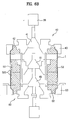
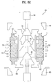
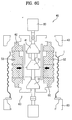
- FIG. 5 illustrates a block diagram showing the steps of a method of fabricating a drum in accordance with a preferred embodiment of the present invention, in more detail, and FIGS. 6A to 6H illustrate structures of the drum and the dies as the steps of a method for fabricating a drum is progresses.
- the device for forming a drum includes an upper die assembly 40, a lower die assembly 60, a middle die assembly 50, and a press (not shown).
- the upper die assembly 40 includes a motor 30, an upper cam 41, an upper core die 42, and an upper outer die 43. The upper die assembly 40 is pressed with the press.
- the upper cam 41 is connected to a rotation axis of the motor 30, and the upper core die 42 can be expanded or contracted in a radial direction along the upper cam 41.
- the upper outer die 43 is at an outer side of the upper core die 42 to be movable in up and down direction, independently.
- the middle die assembly 50 includes a middle cam 51 and a middle core die.
- the middle cam 51 is in line with the rotation axis of the motor 30, and the middle core die 52 can be expanded or contracted in a radial direction along the middle cam 51.
- the lower die assembly 60 has the same system as the upper die assembly 40, and is positioned opposite to the upper die assembly 40. That is, the lower die assembly 60 includes a lower cam 61, a lower core die 62, and a lower outer die 63.
- the lower cam 61 is mounted on a shaft passed through the middle core die 52, and the lower core die 62 can be expanded or contracted in a radial direction along the lower cam 61.
- the lower outer die 63 is at an outer side of the lower core die 62 to be movable in up and down direction, independently.
- the core dies 42, 52 and 62 are cylindrical on the whole each for being in contact with an inside circumferential surface of the drum 1, and are split in a radial direction at predetermined angular intervals for expansion or contraction in the radial direction.
- FIG. 6A illustrates a state the core dies 42, 52 and 62 are expanded in the radial direction, to be in contact with the inside circumferential surface of the drum 1. An inside of each of the core dies is sloped.
- FIG. 6G illustrates a state the core dies 42, 52 and 62 are contracted in the radial direction as the cam 41, 51, and 61 slide. That is, as the shaft having the cams mounted thereon moves up/down, the cams slide along the slope, to expand/contract the core dies.
- FIG. 6A illustrates a drum before opposite end parts thereof are contracted.
- a cylindrical drum 1 is loaded on the drum forming device by inserting the drum 1 on an outside of the middle core dies 52 of the drum forming device.
- the cylindrical drum 1 is fabricated by rolling metal sheet and welding a seam thereof.
- the cylindrical drum 1 inserted on the outside of the middle core die 52 is held by the middle core die 52 and the lower core die 62, and the upper core die 42 is not moved down.
- FIG. 6B illustrates the step of reducing a diameter of an upper end part of the drum as the upper die assembly is moved downward.
- the upper core assembly 40 is pressed downward by the press (not shown). In this instance, the upper end part of the drum 1 is inserted between the upper core die 42 and the upper outer die 43, involving deformation in a form of reducing a diameter of the drum 1.
- FIG. 6C illustrates a state the step of reducing diameters of the upper and lower end parts of the drum is progressed.
- the upper die assembly 40 keeps moving down, when the lower end part of the drum 1 is inserted between the lower core die 62 and the lower outer die 63, finishing the diameter reduction of the lower end part of the drum 1.
- FIG. 6E illustrates the step of forming beads in a middle part of the drum.
- the core dies are rotated, and the rollers 70 on an outside of the drum 1 are moved to respective grooves (520 in FIG. 6D) in the core die 52, and press an outside circumferential surface of the drum 1.
- the rollers 70 are deformed according to forms of the grooves 520, the beads are formed.
- FIG. 6G illustrates a state the core die is contracted to cast off the drum.
- the core dies 42, 52 and 62 are contracted in an arrow direction, to cast off the drum 1. Accordingly, as interference between the drum 1 and the core dies are prevented, the drum 1 can be moved out of the core dies. Meanwhile, before the core dies are contracted, the lower outer die 63 is moved to a position at which the lower outer die 63 can support a bottom end of the drum 1.
- FIG. 6H illustrates a state after the upper die assembly is moved up.
- the drum can be taken out of the device for forming the drum.
- FIG. 7 illustrates a front view of a finished drum by the method for fabricating a drum of the present invention.
- the drum 1 includes a body part 100, reduced parts 110, and bent parts 120.
- the body part is a metal cylinder, with beads 100a in a surface thereof for strengthening.
- the bead 100a is an inwardly recessed part along a circumferential direction of the body part 100.
- the reduced parts 110 are at opposite edges 1a of the body part 100 each with a diameter smaller than a diameter of the body part 100.
- the bent part 120 is a part where an edge of the reduced part 110 is folded.
- the bead 120 is formed by pressing the body part 100 inwardly at a predetermined depth along a circumferential direction of the body part 100 by pressing. It is preferable that there is at least one bead 120.
- the reduced parts 110 are opposite end parts of the body part 100 having diameters contracted by pressing. That is, instead of expanding a diameter of the middle part of the drum 1, diameters of the opposite end parts of the drum 1 are reduced, so that a section of the drum 1 has a more consistent and accurate circular form.
- connection part 111 between the reduced part 110 and the body part 100 having a diameter reduced continuously.
- the connection part 111 is provided for preventing the body part 100 from breaking due to a sharp reduction of the diameter during pressing.
- connection part 111 has the reduced part 110 formed at one end having a reduced diameter, and the reduced part 110 is joined with the front support or the rear support of the dryer.
- the metal cylinder is provided by rolling metal sheet into a cylinder, and butt welding a seam 130 thereof with a plasma-TIG welder in a state opposite edges are not overlapped. This is because, if the opposite edges are overlapped at the seam 130, no uniform deformation can be secured at the overlapped part in the contraction or expansion.
- Predetermined lengths of the opposite edges of the seam as much as to be bent are not welded for forming the bent parts at the opposite edges.
- the metal cylinder has a thickness of 0.5 ⁇ 0.8mm, and, more preferably, 0.55 ⁇ 0.7mm.
- a thickness thinner than 0.5mm is liable to tear during the contraction or expansion of the diameter of the cylinder.
- metal buttons or the like attached to laundry under drying may hit the inside wall of the drum, to produce a loud noise.
- a ratio B/A of an inside diameter of the body part 100 to an inside diameter of the reduced part 110 is greater than 0.9, and more preferably 0.93 ⁇ 0.94.
- the forming for reducing the diameters of opposite edges of the drum 1 uses ductility of metal, the forming is limited by the thickness of the drum 1, and the inside diameter ratio B/A is an optimal ratio suggested for accurate forming at above thickness of the drum 1.
- the metal cylinder is prevented from tearing when the inside diameter ratio B/A is greater than 0.9 at the thickness of the metal optimized by experiment.
- An optimal range of the inside diameter ratio taking safety into account is 0.93 ⁇ 0.94.
- the inside diameter ratio is almost same with a radio of a diameter of the reduced part 110 to a diameter of the body part 100 (an outside diameter ratio).
- a depth C from an outside surface of the body part 100 to an outside surface of the reduced part 110 is 20 ⁇ 23.5mm.
- the thickness of the cylinder is 0.5mm
- the outside diameter of the body part 100 is 663mm
- a ratio of the inside diameter of the body part 100 to the inside diameter of the reduced part is 0.9, with a difference of outside diameters of the body part 100 and the reduced part 110 being 67mm
- the depth C from an outside surface of the body part 100 to an outside surface of the reduced part 110 is 33.5mm. If the depth is greater than 33.5mm, the cylinder is liable to tear during the formation.
- the depth C from the outside surface of the body part 100 to the outside surface of the reduced part 110 is maintained to be below 25mm.
- the cylinder has a thickness of 0.6mm, it is preferable that the depth is around 44mm.
- anti-vibration band 140 wound on the outside surface of the body part 100 or on the beads 100a.
- the anti-vibration band 140 absorbs or reduces noise and vibration caused by laundry in the drum 1.
- the anti-vibration band 140 is rubber or metal, and tightly attached to the outside surface of the body part 100 or the beads 100a.
- the drum 1 is formed of stainless steel STS having a good strength and a glossy exterior.
- the drum 1 may be formed of Alstar or Alcostar, having a good corrosion resistance, and a comparatively low cost.
- the stainless steel in view of improvement of exterior, the stainless steel is favorable, and in view of corrosion or cost, Alstar or Alcostar is favorable.
- the drum 1 may be formed of EGI (Electrolytic Zinc Coated Steel, SECC), GI (Hot Dip Zinc Coated Steel, SGCC), Galvanneld steel, Galvalume (GL), SFCH, or SGCH.
- EGI Electrolytic Zinc Coated Steel
- GI Hot Dip Zinc Coated Steel
- Galvanneld steel Galvalume (GL)
- SFCH Galvalume
- SGCH Galvalume
- zinc is plated on the surface of the metal cylinder, or a painting layer is formed.
- the drum is applicable not only to the dryer, but also to a washer.
- the drum for a washer and a dryer of the present invention has the following advantages.
- the drum of the present invention is formed, not by expanding a middle part of the drum, but contracting opposite end parts of the drum. According to this, the pressing trace of core dies on the middle part of the drum 1 which is harmful to an outer appearance of the drum is eliminated. Moreover, by not pressing the middle part of the drum 1, the circular form of the middle part of the drum is not impaired. According to this, the drum fabricated according to the present invention has a continuous form, and can minimize vibration and noise during rotation.
- the present invention improves a method for fabricating a drum for a dryer, to maintain an overall circular form of the drum, and to improve reliability of the dryer.
- the present invention has been described taking a drum for a dryer as an example, the present invention can be applied to a drum for washer or the like.
Landscapes
- Engineering & Computer Science (AREA)
- Textile Engineering (AREA)
- Mechanical Engineering (AREA)
- Detail Structures Of Washing Machines And Dryers (AREA)
- Main Body Construction Of Washing Machines And Laundry Dryers (AREA)
- Treatment Of Fiber Materials (AREA)
Claims (10)
- Tambour (1) pour une machine à laver et un sèche-linge comprenant:une partie de corps métallique cylindrique (100);des parties réduites (110) aux extrémités opposées de la partie de corps, chacune d'un diamètre inférieur à un diamètre de la partie de corps; etdes parties pliées (120) ayant un bord plié de la partie réduite.
- Tambour selon la revendication 1, où la partie réduite inclut la partie d'extrémité opposée de la partie de corps ayant un diamètre réduit par pressage; et/ou
où le cyclindre métallique est plaqué zinc; et/ou
où le métal est de l'acier inoxydable STS; et/ou
où le métal est EGI (Tôle électrozinguée en Acier, SECC); et/ou
où le métal est GI (Acier galvanisé par immersion, SGCC); et/ou
où le métal est de l'acier galvanisé; et/ou
où le métal est du Galvalume GL (acier revêtu d'un alliage aluminium-zinc); et/ou
où le métal est du Alstar (acier aluminé immergé); et/ou
où le métal est du Alcostar (acier revêtu d'aluminium); et/ou
où le métal est du SFCH; et/ou
où le métal est du SGCH; et/ou
où le cylindre métallique comprend une surface peinte; et/ou
où la partie de corps est formée en laminant une tôle métallique avec un cylindre et en soudant bout-à-bout un soudage, ayant des bourrelets formés dans une surface en vue d'un renforcement, et où le bourrelet est formé en pressant la partie de corps vers l'intérieur sur une profondeur prédéterminée le long d'une direction circonférentielle de la partie de corps par pressage. - Tambour selon la revendication 1, où le corps cylindrique est formé en laminant une tôle métallique et en soudant bout-à-bout une soudure; et de préférence où le soudage bout-à-bout est exécuté à l'exception de longueurs prédéterminées de bords opposés de la soudure dans une direction de la longueur pour former les parties pliées.
- Tambour selon la revendication 1, où le cylindre métallique a une épaisseur de 0,5-0,8 mm.
- Tambour selon la revendication 4, où le cylindre métallique a une épaisseur de 0,55-0,7 mm; et/ou où une différence de profondeur entre un diamètre externe de la partie de corps adjacente à la partie réduite et un diamètre externe de la partie réduite est inférieure à 25 mm.
- Tambour selon la revendication 4, où un rapport d'un diamètre interne de la partie de corps au diamètre interne de la partie réduite est égal ou supérieur à 0,9; et de préférence où le rapport d'un diamètre interne de la partie de corps au diamètre interne de la partie réduite est de 0,93-0,94.
- Tambour selon la revendication 1, comprenant en outre une bande anti-vibration enroulée sur une surface externe de la partie de corps pour absorber les vibrations; et de préférence où la bande anti-vibration est réalisée en caoutchouc; et/ou où la bande anti-vibrations est réalisée en métal.
- Tambour pour une machine à laver et un sèche-linge selon la revendication 1, où la partie de corps est formée en laminant une tôle métallique en un cyclindre, et en soudant bout-à-bout une soudure, ayant des bourrelets formés dans une surface en vue d'un renforcement; et comprenant en outre
des parties de connection ayant des diamètres réduits continuellement à partir des côtés opposés de la partie de corps par pressage, respectivement; et où les parties réduites s'étendent d'une extrémité des parties de connection par pressage, respectivement. - Tambour selon la revendication 1, dans lequel:la partie de corps est formée en laminant la tôle métallique en un cylindre et en soudant bout-à-bout une soudure, avec des bourrelets formés dans une surface pour le renforcement;les parties réduites sont formées en réduisant les diamètres des parties d'extrémité opposées de la partie de corps par pressage; et comprenant en outreune bande anti-vibration enroulée sur une surface extérieure de la partie de corps afin d'absorber les vibrations.
- Tambour selon la revendication 1, dans lequel:la partie de corps est formée en laminant une tôle métallique en un cylindre et en soudant bout-à-bout une soudure;les parties réduites sont formées en réduisant les diamètres des parties d'extrémité opposées de la partie de corps par pressage;et comprenant en outreune bande anti-vibration enroulée sur une surface extérieure de la partie de corps pour absorber les vibrations.
Applications Claiming Priority (3)
| Application Number | Priority Date | Filing Date | Title |
|---|---|---|---|
| KR20030036393 | 2003-06-05 | ||
| KR1020040003532A KR100444556B1 (ko) | 2003-06-05 | 2004-01-17 | 건조기용 드럼 구조 및 성형방법 |
| PCT/KR2004/001316 WO2004109004A1 (fr) | 2003-06-05 | 2004-06-03 | Tambour pour machine a laver ou seche linge |
Publications (2)
| Publication Number | Publication Date |
|---|---|
| EP1629147A1 EP1629147A1 (fr) | 2006-03-01 |
| EP1629147B1 true EP1629147B1 (fr) | 2007-07-18 |
Family
ID=33513444
Family Applications (1)
| Application Number | Title | Priority Date | Filing Date |
|---|---|---|---|
| EP04736016A Revoked EP1629147B1 (fr) | 2003-06-05 | 2004-06-03 | Tambour pour machine a laver ou seche linge |
Country Status (6)
| Country | Link |
|---|---|
| US (3) | US8365437B2 (fr) |
| EP (1) | EP1629147B1 (fr) |
| AU (1) | AU2004245856B2 (fr) |
| DE (1) | DE602004007651T2 (fr) |
| ES (1) | ES2289521T3 (fr) |
| WO (1) | WO2004109004A1 (fr) |
Families Citing this family (17)
| Publication number | Priority date | Publication date | Assignee | Title |
|---|---|---|---|---|
| USD532566S1 (en) * | 2004-03-08 | 2006-11-21 | Lg Electronics Inc. | Direct drive structure of drum washing machine |
| CA108279S (en) * | 2004-03-08 | 2006-03-10 | Lg Electronics Inc | Driving part structure of drum washing machine |
| WO2006126814A2 (fr) * | 2005-05-23 | 2006-11-30 | Lg Electronics Inc. | Lave-linge de type a tambour et methode de fabrication du tambour correspondant |
| KR101275198B1 (ko) | 2005-05-23 | 2013-06-18 | 엘지전자 주식회사 | 드럼세탁기 및 그에 적용되는 드럼 제조방법 |
| DE102006029951A1 (de) * | 2006-06-29 | 2008-01-03 | BSH Bosch und Siemens Hausgeräte GmbH | Verfahren und Vorrichtung zum Prägen eines Trommelmantels |
| KR101245589B1 (ko) * | 2006-10-02 | 2013-03-20 | 엘지전자 주식회사 | 냄새제거기능을 구비한 세탁기 |
| ES2306605B1 (es) * | 2007-04-04 | 2009-06-17 | Bsh Electrodomesticos España, S.A. | Tambor de una maquina de tratado cuidadoso de la ropa. |
| USD652591S1 (en) * | 2011-01-05 | 2012-01-17 | Samsung Electronics Co., Ltd. | Drum for drum-type washing machine |
| CN103639323A (zh) * | 2013-12-10 | 2014-03-19 | 合肥亚辰机械制造有限公司 | 洗衣机不锈钢内桶制造的专用设备及其制造方法 |
| USD743131S1 (en) * | 2014-01-03 | 2015-11-10 | Samsung Electronics Co., Ltd. | Drum for washing machine |
| USD753357S1 (en) * | 2014-06-20 | 2016-04-05 | Wuxi Little Swan Co., Ltd | Inner barrel with dehydrating hole of washing machine |
| CN106825181B (zh) * | 2016-12-09 | 2018-06-26 | 宁波大学 | 一种锥形薄壁回转件的普旋成形装置 |
| US11629448B2 (en) * | 2017-03-13 | 2023-04-18 | Midea Group Co., Ltd. | Laundry washing machine with adjustable wash capacity |
| USD836864S1 (en) * | 2017-03-23 | 2018-12-25 | Samsung Electronics Co., Ltd. | Drum for washing machine |
| CN112414050A (zh) * | 2020-11-03 | 2021-02-26 | 许文祥 | 一种饲料加工用烘干翻转机 |
| CN114770052A (zh) * | 2022-05-24 | 2022-07-22 | 孙继成 | 一种用于烘干机上的焊接处理方法 |
| DE102024203167A1 (de) * | 2024-04-08 | 2025-10-09 | BSH Hausgeräte GmbH | Wäschetrommel mit volumenerweiternden Expansionsringbereichen, Haushaltsgerät und Verfahren zum Herstellen einer Wäschetrommel |
Family Cites Families (70)
| Publication number | Priority date | Publication date | Assignee | Title |
|---|---|---|---|---|
| GB190720898A (en) | 1906-09-20 | 1907-11-07 | James Thomas Barker | An Improved Back-band and Trace Buckle. |
| GB136510A (en) | 1919-09-09 | 1919-12-18 | Stewart Campbell | Improvements in the Manufacture of Metallic Drums, Barrels and like Receptacles. |
| US1645971A (en) * | 1922-08-25 | 1927-10-18 | Clarence H Riegel | Method of making sheet-metal barrels |
| GB283673A (en) | 1926-11-02 | 1928-01-19 | Reads Ltd | Improvements in and relating to the manufacture of sheet metal drums, canisters or similar receptacles |
| US1698999A (en) * | 1927-01-24 | 1929-01-15 | American Can Co | Necking-in or reforming tubular bodies |
| GB399132A (en) | 1933-06-09 | 1933-09-28 | Thomas Dunlop Carpenter | Improvements in and relating to the manufacture of metal drums, tanks and like vessels |
| US3163142A (en) * | 1961-06-30 | 1964-12-29 | Fred W Buhrke | Die assembly |
| US3272671A (en) * | 1963-08-28 | 1966-09-13 | Greif Bros Cooperage Corp | Method of making a composite fiber and metal tubular container body |
| GB1059002A (en) | 1965-01-07 | 1967-02-15 | Crosshall Engineering Company | Improvements in or relating to apparatus for the manufacture of metal drums and containers |
| US3399464A (en) | 1966-09-16 | 1968-09-03 | Gen Electric | Clothes dryer |
| NL7006581A (fr) | 1969-05-13 | 1970-11-17 | Montedison Spa | |
| US3584393A (en) | 1969-10-31 | 1971-06-15 | Gen Motors Corp | Split drum dryer |
| US3685338A (en) * | 1970-04-24 | 1972-08-22 | Krause Ass F A | Hem formation |
| US3765351A (en) * | 1971-04-09 | 1973-10-16 | American Can Co | Method and apparatus for beading, necking-in and flanging metal can bodies |
| US3789514A (en) | 1972-07-24 | 1974-02-05 | Maytag Co | Bulkhead filter assembly |
| US3816942A (en) | 1972-07-24 | 1974-06-18 | Maytag Co | Bulkhead seal for clothes dryer |
| US3815258A (en) | 1972-11-30 | 1974-06-11 | Whirlpool Co | Dryer having drum with two different diameters |
| GB1391043A (en) | 1973-06-14 | 1975-04-16 | Philips Electronic Associated | Domestic appliances |
| JPS53116267A (en) | 1977-03-23 | 1978-10-11 | Mitsubishi Plastics Ind Ltd | Manufacture of branched pipe joint |
| US4170888A (en) * | 1978-06-30 | 1979-10-16 | Motor Wheel Corporation | Apparatus for spin-forming wheel rims |
| NL7807744A (nl) | 1978-07-19 | 1980-01-22 | Monfalconesi E Passero & C S R | Cilindrisch of conisch metalen vat met een, op de uit het lichaam van het vat gevormde ring zittende persdek- selsluiting en de bijpassende vervaardigingswijze. |
| JPS5633138A (en) | 1979-08-24 | 1981-04-03 | Kawasaki Heavy Ind Ltd | Manufacture of container trunk of noncircular section having helical groove on inside wall |
| JPS5816781A (ja) | 1981-07-24 | 1983-01-31 | Sumitomo Metal Ind Ltd | 溶接管の製造方法 |
| ATE33267T1 (de) * | 1981-09-25 | 1988-04-15 | Procter & Gamble | Aminosilanen enthaltende koernige reinigungsmittelgemische. |
| US4430809A (en) | 1981-11-24 | 1984-02-14 | Whirlpool Corporation | Front drum access and support for dryer |
| FR2530536B1 (fr) | 1982-07-26 | 1986-12-26 | Nisshin Steel Co Ltd | Tole d'acier couverte d'aluminium et procede pour sa production |
| DE3227853C2 (de) | 1982-07-26 | 1987-03-05 | Nisshin Steel Co., Ltd., Tokio/Tokyo | Mit Aluminium überzogenes Stahlblech und Verfahren zu dessen Herstellung |
| JPS5985999A (ja) * | 1982-11-08 | 1984-05-18 | 秩父セメント株式会社 | 多重型容器およびその製造方法 |
| DE3335009A1 (de) | 1983-09-28 | 1985-04-18 | Metallgesellschaft Ag, 6000 Frankfurt | Verfahren zur elektrolytischen verzinkung von stahl |
| US4721286A (en) | 1985-07-24 | 1988-01-26 | Amca International Corporation | Split block for extended travel |
| DE3529160A1 (de) * | 1985-08-14 | 1987-02-26 | Nippon Steel Corp | Formwalzvorrichtung |
| IT1191525B (it) | 1986-02-27 | 1988-03-23 | Zanussi Zeltron Inst | Procedimento per la fabbricazione di vasche per macchine |
| FR2602743B1 (fr) | 1986-08-05 | 1988-11-18 | Gallay Sa | Procede de fabrication de corps de fut muni de joncs de roulement, et corps de fut ainsi realises |
| FR2667521B2 (fr) | 1986-08-05 | 1993-08-06 | Gallay Sa | Procede de fabrication de corps de fut muni de joncs de roulement et corps de fut ainsi realises. |
| JPH0673935B2 (ja) * | 1988-04-01 | 1994-09-21 | ニチアス株式会社 | 制振材および制振材を用いた防音構造体 |
| US4854054A (en) * | 1988-06-27 | 1989-08-08 | Maytag Corporation | Fabric dryer airflow system |
| US5246563A (en) | 1988-09-14 | 1993-09-21 | Andritz-Patentverwaltungs-Gesellschaft M.B.H. | Process for the electrolytic zinc coating of stainless steel |
| US4890786A (en) * | 1988-10-11 | 1990-01-02 | Sonoco Products Company | Fibre drum with reinforcement collar |
| JPH0318439A (ja) | 1989-06-14 | 1991-01-28 | Motozou Ueda | 流し台用水切篭の製造方法 |
| JPH04214895A (ja) | 1990-02-21 | 1992-08-05 | Kawasaki Steel Corp | めっき性と溶接性に優れた表面処理鋼板およびその製造方法 |
| US5127169A (en) | 1991-01-25 | 1992-07-07 | Maytag Corporation | Clothes dryer |
| SE468209B (sv) | 1991-08-21 | 1992-11-23 | Sandvik Ab | Anvaendning av en austenitisk krom-nickel-molybden- jaernlegering foer tillverkning av kompoundroer foer anvaendning som bottentuber i sodahuspannor |
| US5277746A (en) | 1992-07-27 | 1994-01-11 | Texas Instruments Incorporated | High pressure liquid phase epitaxy reactor chamber and method with direct see through capability |
| WO1994027280A1 (fr) | 1993-05-18 | 1994-11-24 | Stephen Frederick Shier | Tambour |
| JP2639890B2 (ja) | 1993-10-14 | 1997-08-13 | 新日本製鐵株式会社 | 溶融Znめっきで防食を施した石油貯蔵タンク |
| JPH07155869A (ja) | 1993-12-06 | 1995-06-20 | Kobe Steel Ltd | 金属缶のネックイン加工用工具 |
| KR960007551B1 (ko) | 1994-03-10 | 1996-06-05 | 연합철강공업 주식회사 | 도금 강판의 제조방법 |
| US5996386A (en) * | 1994-04-21 | 1999-12-07 | Pazzaglia; Luigi | Equipment and method for edging and tapering cylindrical body cans |
| KR0135246B1 (ko) | 1994-07-08 | 1998-04-22 | 김주용 | 미세환형패턴을 이용한 이중실린더 전하저장전극 형성방법 |
| KR0135675B1 (ko) | 1994-09-28 | 1998-04-24 | 최훈 | 옥상단열방수공법 및 옥상단열방수구조 |
| US5784911A (en) * | 1995-02-09 | 1998-07-28 | Kusakabe Electric & Machinery Co., Ltd. | Apparatus for manufacturing a welded pipe |
| KR100358938B1 (ko) | 1995-10-14 | 2003-01-24 | 주식회사 포스코 | 용접부의내후성이우수한스테인리스강판의제조방법 |
| JPH10249459A (ja) | 1997-03-11 | 1998-09-22 | Nakagawa Sangyo Kk | 金属製パイプの縮管方法 |
| SE9702212L (sv) * | 1997-06-10 | 1998-12-11 | Electrolux Ab | Tvätt- eller torkmaskin med integrerad trumgavelaxel |
| CA2208388C (fr) * | 1997-06-20 | 2005-06-14 | Camco Inc. | Secheuse avec tambour a insonorisation amelioree |
| JPH11342429A (ja) | 1998-06-01 | 1999-12-14 | Jatco Corp | ボス付きドラムの製造方法とボス付きドラム |
| US5950472A (en) | 1998-08-13 | 1999-09-14 | Atlanta Grothes Machine Company | Bead-formation in metal drum manufacture |
| DE19838332A1 (de) | 1998-08-24 | 2000-03-02 | Schloemann Siemag Ag | Verfahren und Vorrichtung zur Qualitätsüberwachung und -regelung des Galvannealed-Überzuges von Stahlbändern |
| JP4374111B2 (ja) | 2000-03-17 | 2009-12-02 | 中央精機株式会社 | 自動車ホイール用リムの製造方法 |
| JP4253998B2 (ja) | 2000-03-30 | 2009-04-15 | Jfeスチール株式会社 | 溶融亜鉛めっき鋼板の調質圧延方法 |
| JP3743496B2 (ja) | 2000-07-27 | 2006-02-08 | トヨタ自動車株式会社 | 触媒コンバータの製造方法およびスピニング加工装置 |
| CN2443979Y (zh) | 2000-10-01 | 2001-08-22 | 中外合资合肥荣事达洗衣机有限公司 | 洗衣机洗涤桶 |
| JP3644402B2 (ja) | 2001-04-05 | 2005-04-27 | Jfeスチール株式会社 | 合金化溶融亜鉛めっき鋼板 |
| JP2002327257A (ja) | 2001-04-26 | 2002-11-15 | Nippon Steel Corp | プレス成形性に優れた溶融アルミめっき鋼板とその製造方法 |
| JP2002332557A (ja) | 2001-05-14 | 2002-11-22 | Nisshin Steel Co Ltd | 溶融アルミニウムめっき鋼板の製造方法 |
| US6516507B2 (en) | 2001-06-15 | 2003-02-11 | Knoll, Inc. | Method of making a metal drawer head |
| KR100593635B1 (ko) | 2001-07-19 | 2006-06-28 | 주식회사 엘지이아이 | 가전기기용 드럼장치 |
| KR100558059B1 (ko) | 2001-10-17 | 2006-03-07 | 주식회사 포스코 | 젖음성 및 고온 산화성을 향상시킨 스테인레스 알루미늄용융도금강판의 제조방법 |
| KR100451792B1 (ko) | 2001-12-15 | 2004-10-08 | 엘지전자 주식회사 | Isa버스를 이용한 시스템과의 pb버스 인터페이스로직 |
| CN2536625Y (zh) | 2001-12-22 | 2003-02-19 | 海尔集团公司 | 洗衣机内桶 |
-
2004
- 2004-06-03 EP EP04736016A patent/EP1629147B1/fr not_active Revoked
- 2004-06-03 US US10/528,830 patent/US8365437B2/en not_active Expired - Fee Related
- 2004-06-03 DE DE602004007651T patent/DE602004007651T2/de not_active Expired - Lifetime
- 2004-06-03 AU AU2004245856A patent/AU2004245856B2/en not_active Ceased
- 2004-06-03 WO PCT/KR2004/001316 patent/WO2004109004A1/fr not_active Ceased
- 2004-06-03 ES ES04736016T patent/ES2289521T3/es not_active Expired - Lifetime
-
2010
- 2010-10-01 US US12/896,310 patent/US20110056086A1/en not_active Abandoned
-
2011
- 2011-04-21 US US13/091,984 patent/US8083122B2/en not_active Expired - Fee Related
Also Published As
| Publication number | Publication date |
|---|---|
| AU2004245856B2 (en) | 2009-09-10 |
| US20110056086A1 (en) | 2011-03-10 |
| US8365437B2 (en) | 2013-02-05 |
| EP1629147A1 (fr) | 2006-03-01 |
| WO2004109004A1 (fr) | 2004-12-16 |
| DE602004007651T2 (de) | 2008-06-05 |
| US20110192886A1 (en) | 2011-08-11 |
| AU2004245856A1 (en) | 2004-12-16 |
| US20060005585A1 (en) | 2006-01-12 |
| US8083122B2 (en) | 2011-12-27 |
| DE602004007651D1 (de) | 2007-08-30 |
| ES2289521T3 (es) | 2008-02-01 |
Similar Documents
| Publication | Publication Date | Title |
|---|---|---|
| US8083122B2 (en) | Drum for washer and dryer | |
| CN100547145C (zh) | 用于洗衣机和干衣机的滚筒 | |
| US7340849B2 (en) | Drum in dryer and method for fabricating the same | |
| US7743480B2 (en) | Method of manufacturing a drum-type washing machine | |
| EP1541738B1 (fr) | Moteur à rotor extérieur pour machine à laver à tambour et méthode de fabrication pour celui-ci | |
| CA2584949C (fr) | Amortisseur a tube | |
| KR20050115726A (ko) | 건조기의 드럼 구조 | |
| KR101181757B1 (ko) | 건조기용 드럼 구조 및 그 제조방법 | |
| KR101100158B1 (ko) | 건조기용 드럼 구조 및 그 제조방법 | |
| US20220228309A1 (en) | Drum structure for laundry treatment device and method of manufacturing drum | |
| KR20050079676A (ko) | 건조기용 드럼 성형방법 및 그에 따라 제조된 드럼 구조 | |
| KR19990029483A (ko) | 촉매용 벌집형체구조 | |
| KR100617180B1 (ko) | 드럼세탁기의 터브 구조 및 그 제조방법 | |
| KR102845090B1 (ko) | 드럼의 제조방법 및 상기 드럼을 포함하는 의류처리장치 | |
| KR20220104546A (ko) | 세탁물 처리장치용 드럼 제조방법 | |
| KR20050070399A (ko) | 건조기용 드럼 성형방법 |
Legal Events
| Date | Code | Title | Description |
|---|---|---|---|
| PUAI | Public reference made under article 153(3) epc to a published international application that has entered the european phase |
Free format text: ORIGINAL CODE: 0009012 |
|
| 17P | Request for examination filed |
Effective date: 20060105 |
|
| RBV | Designated contracting states (corrected) |
Designated state(s): DE ES FR GB IT TR |
|
| R17P | Request for examination filed (corrected) |
Effective date: 20060105 |
|
| RBV | Designated contracting states (corrected) |
Designated state(s): DE ES FR GB IT TR |
|
| DAX | Request for extension of the european patent (deleted) | ||
| RBV | Designated contracting states (corrected) |
Designated state(s): DE ES FR GB IT TR |
|
| 17Q | First examination report despatched |
Effective date: 20060908 |
|
| GRAP | Despatch of communication of intention to grant a patent |
Free format text: ORIGINAL CODE: EPIDOSNIGR1 |
|
| GRAS | Grant fee paid |
Free format text: ORIGINAL CODE: EPIDOSNIGR3 |
|
| GRAA | (expected) grant |
Free format text: ORIGINAL CODE: 0009210 |
|
| AK | Designated contracting states |
Kind code of ref document: B1 Designated state(s): DE ES FR GB IT TR |
|
| REF | Corresponds to: |
Ref document number: 602004007651 Country of ref document: DE Date of ref document: 20070830 Kind code of ref document: P |
|
| ET | Fr: translation filed | ||
| REG | Reference to a national code |
Ref country code: ES Ref legal event code: FG2A Ref document number: 2289521 Country of ref document: ES Kind code of ref document: T3 |
|
| PLBI | Opposition filed |
Free format text: ORIGINAL CODE: 0009260 |
|
| PLAX | Notice of opposition and request to file observation + time limit sent |
Free format text: ORIGINAL CODE: EPIDOSNOBS2 |
|
| 26 | Opposition filed |
Opponent name: ELECTROLUX HOME PRODUCTS N.V. Effective date: 20080418 |
|
| PLAF | Information modified related to communication of a notice of opposition and request to file observations + time limit |
Free format text: ORIGINAL CODE: EPIDOSCOBS2 |
|
| PLBB | Reply of patent proprietor to notice(s) of opposition received |
Free format text: ORIGINAL CODE: EPIDOSNOBS3 |
|
| RDAF | Communication despatched that patent is revoked |
Free format text: ORIGINAL CODE: EPIDOSNREV1 |
|
| APBM | Appeal reference recorded |
Free format text: ORIGINAL CODE: EPIDOSNREFNO |
|
| APBP | Date of receipt of notice of appeal recorded |
Free format text: ORIGINAL CODE: EPIDOSNNOA2O |
|
| APAH | Appeal reference modified |
Free format text: ORIGINAL CODE: EPIDOSCREFNO |
|
| APBQ | Date of receipt of statement of grounds of appeal recorded |
Free format text: ORIGINAL CODE: EPIDOSNNOA3O |
|
| PGFP | Annual fee paid to national office [announced via postgrant information from national office to epo] |
Ref country code: GB Payment date: 20140513 Year of fee payment: 11 |
|
| PGFP | Annual fee paid to national office [announced via postgrant information from national office to epo] |
Ref country code: IT Payment date: 20140619 Year of fee payment: 11 Ref country code: TR Payment date: 20140527 Year of fee payment: 11 Ref country code: ES Payment date: 20140522 Year of fee payment: 11 Ref country code: DE Payment date: 20140513 Year of fee payment: 11 Ref country code: FR Payment date: 20140513 Year of fee payment: 11 |
|
| REG | Reference to a national code |
Ref country code: DE Ref legal event code: R103 Ref document number: 602004007651 Country of ref document: DE Ref country code: DE Ref legal event code: R064 Ref document number: 602004007651 Country of ref document: DE |
|
| APBU | Appeal procedure closed |
Free format text: ORIGINAL CODE: EPIDOSNNOA9O |
|
| RDAG | Patent revoked |
Free format text: ORIGINAL CODE: 0009271 |
|
| STAA | Information on the status of an ep patent application or granted ep patent |
Free format text: STATUS: PATENT REVOKED |
|
| 27W | Patent revoked |
Effective date: 20141014 |
|
| GBPR | Gb: patent revoked under art. 102 of the ep convention designating the uk as contracting state |
Effective date: 20141014 |
|
| REG | Reference to a national code |
Ref country code: DE Ref legal event code: R107 Ref document number: 602004007651 Country of ref document: DE Effective date: 20150219 |