EP1630002A1 - Pneumatique à câble métallique et procédé de fabrication de câbles métalliques - Google Patents
Pneumatique à câble métallique et procédé de fabrication de câbles métalliques Download PDFInfo
- Publication number
- EP1630002A1 EP1630002A1 EP05016906A EP05016906A EP1630002A1 EP 1630002 A1 EP1630002 A1 EP 1630002A1 EP 05016906 A EP05016906 A EP 05016906A EP 05016906 A EP05016906 A EP 05016906A EP 1630002 A1 EP1630002 A1 EP 1630002A1
- Authority
- EP
- European Patent Office
- Prior art keywords
- cord
- filaments
- metal
- cords
- range
- Prior art date
- Legal status (The legal status is an assumption and is not a legal conclusion. Google has not performed a legal analysis and makes no representation as to the accuracy of the status listed.)
- Granted
Links
- 229910052751 metal Inorganic materials 0.000 title claims abstract description 60
- 239000002184 metal Substances 0.000 title claims abstract description 60
- 238000004519 manufacturing process Methods 0.000 title claims abstract description 6
- 238000007493 shaping process Methods 0.000 claims abstract description 7
- 238000000034 method Methods 0.000 claims 1
- 239000011324 bead Substances 0.000 description 22
- 230000003014 reinforcing effect Effects 0.000 description 13
- 229910000831 Steel Inorganic materials 0.000 description 11
- 239000010959 steel Substances 0.000 description 11
- 238000012360 testing method Methods 0.000 description 11
- 230000003247 decreasing effect Effects 0.000 description 5
- 230000035515 penetration Effects 0.000 description 5
- 230000000717 retained effect Effects 0.000 description 5
- 230000007423 decrease Effects 0.000 description 4
- 239000012141 concentrate Substances 0.000 description 3
- 239000000835 fiber Substances 0.000 description 2
- 239000000463 material Substances 0.000 description 2
- 229920001875 Ebonite Polymers 0.000 description 1
- ZOKXTWBITQBERF-UHFFFAOYSA-N Molybdenum Chemical compound [Mo] ZOKXTWBITQBERF-UHFFFAOYSA-N 0.000 description 1
- 239000004677 Nylon Substances 0.000 description 1
- 230000002411 adverse Effects 0.000 description 1
- 230000015572 biosynthetic process Effects 0.000 description 1
- 230000001427 coherent effect Effects 0.000 description 1
- 230000008602 contraction Effects 0.000 description 1
- 238000001816 cooling Methods 0.000 description 1
- 238000010586 diagram Methods 0.000 description 1
- 238000006073 displacement reaction Methods 0.000 description 1
- 238000009826 distribution Methods 0.000 description 1
- 238000005098 hot rolling Methods 0.000 description 1
- 238000012986 modification Methods 0.000 description 1
- 230000004048 modification Effects 0.000 description 1
- 229910052750 molybdenum Inorganic materials 0.000 description 1
- 239000011733 molybdenum Substances 0.000 description 1
- 229920001778 nylon Polymers 0.000 description 1
- 238000007747 plating Methods 0.000 description 1
Images


Classifications
-
- D—TEXTILES; PAPER
- D07—ROPES; CABLES OTHER THAN ELECTRIC
- D07B—ROPES OR CABLES IN GENERAL
- D07B1/00—Constructional features of ropes or cables
- D07B1/06—Ropes or cables built-up from metal wires, e.g. of section wires around a hemp core
- D07B1/0606—Reinforcing cords for rubber or plastic articles
- D07B1/0646—Reinforcing cords for rubber or plastic articles comprising longitudinally preformed wires
- D07B1/0653—Reinforcing cords for rubber or plastic articles comprising longitudinally preformed wires in the core
-
- B—PERFORMING OPERATIONS; TRANSPORTING
- B60—VEHICLES IN GENERAL
- B60C—VEHICLE TYRES; TYRE INFLATION; TYRE CHANGING; CONNECTING VALVES TO INFLATABLE ELASTIC BODIES IN GENERAL; DEVICES OR ARRANGEMENTS RELATED TO TYRES
- B60C9/00—Reinforcements or ply arrangement of pneumatic tyres
- B60C9/0007—Reinforcements made of metallic elements, e.g. cords, yarns, filaments or fibres made from metal
-
- B—PERFORMING OPERATIONS; TRANSPORTING
- B60—VEHICLES IN GENERAL
- B60C—VEHICLE TYRES; TYRE INFLATION; TYRE CHANGING; CONNECTING VALVES TO INFLATABLE ELASTIC BODIES IN GENERAL; DEVICES OR ARRANGEMENTS RELATED TO TYRES
- B60C9/00—Reinforcements or ply arrangement of pneumatic tyres
- B60C9/0057—Reinforcements comprising preshaped elements, e.g. undulated or zig-zag filaments
-
- B—PERFORMING OPERATIONS; TRANSPORTING
- B60—VEHICLES IN GENERAL
- B60C—VEHICLE TYRES; TYRE INFLATION; TYRE CHANGING; CONNECTING VALVES TO INFLATABLE ELASTIC BODIES IN GENERAL; DEVICES OR ARRANGEMENTS RELATED TO TYRES
- B60C9/00—Reinforcements or ply arrangement of pneumatic tyres
- B60C9/02—Carcasses
-
- D—TEXTILES; PAPER
- D07—ROPES; CABLES OTHER THAN ELECTRIC
- D07B—ROPES OR CABLES IN GENERAL
- D07B1/00—Constructional features of ropes or cables
- D07B1/06—Ropes or cables built-up from metal wires, e.g. of section wires around a hemp core
- D07B1/0606—Reinforcing cords for rubber or plastic articles
- D07B1/0646—Reinforcing cords for rubber or plastic articles comprising longitudinally preformed wires
-
- D—TEXTILES; PAPER
- D07—ROPES; CABLES OTHER THAN ELECTRIC
- D07B—ROPES OR CABLES IN GENERAL
- D07B2201/00—Ropes or cables
- D07B2201/20—Rope or cable components
- D07B2201/2001—Wires or filaments
- D07B2201/2006—Wires or filaments characterised by a value or range of the dimension given
-
- D—TEXTILES; PAPER
- D07—ROPES; CABLES OTHER THAN ELECTRIC
- D07B—ROPES OR CABLES IN GENERAL
- D07B2201/00—Ropes or cables
- D07B2201/20—Rope or cable components
- D07B2201/2001—Wires or filaments
- D07B2201/2007—Wires or filaments characterised by their longitudinal shape
- D07B2201/2008—Wires or filaments characterised by their longitudinal shape wavy or undulated
-
- D—TEXTILES; PAPER
- D07—ROPES; CABLES OTHER THAN ELECTRIC
- D07B—ROPES OR CABLES IN GENERAL
- D07B2201/00—Ropes or cables
- D07B2201/20—Rope or cable components
- D07B2201/2015—Strands
- D07B2201/2022—Strands coreless
-
- D—TEXTILES; PAPER
- D07—ROPES; CABLES OTHER THAN ELECTRIC
- D07B—ROPES OR CABLES IN GENERAL
- D07B2201/00—Ropes or cables
- D07B2201/20—Rope or cable components
- D07B2201/2015—Strands
- D07B2201/2024—Strands twisted
-
- D—TEXTILES; PAPER
- D07—ROPES; CABLES OTHER THAN ELECTRIC
- D07B—ROPES OR CABLES IN GENERAL
- D07B2201/00—Ropes or cables
- D07B2201/20—Rope or cable components
- D07B2201/2015—Strands
- D07B2201/2038—Strands characterised by the number of wires or filaments
- D07B2201/204—Strands characterised by the number of wires or filaments nine or more wires or filaments respectively forming multiple layers
-
- D—TEXTILES; PAPER
- D07—ROPES; CABLES OTHER THAN ELECTRIC
- D07B—ROPES OR CABLES IN GENERAL
- D07B2501/00—Application field
- D07B2501/20—Application field related to ropes or cables
- D07B2501/2046—Tyre cords
Definitions
- the present invention relates to a pneumatic tire, more particularly to a metal cord having a specific initial elongation being capable of improving the tire durability.
- steel cords are widely used as tension members to reinforce various tire components, for examples, a carcass in a heavy duty tire, a tread reinforcing belt, a bead reinforcing layer and the like.
- 3xd+9xd indicates that a core is made up of three steel filaments having a diameter (d) and an outer sheath is made up of nine steel filaments having the diameter (d).
- 3xd+9xd+1xd indicates that a steel filament having the diameter (d) is wound around the "3xd+9xd” structure as an additional wrapping wire.
- the carcass cords embedded in the tire grow or their lengths increase during use.
- the cord becomes longer.
- the load concentrates on the shorter cords.
- the shorter cords are liable to fatigue more than the longer cords, and the durability is decreased.
- a primary object of the present invention is therefore, to provide a pneumatic tire of which durability is improved by specifically limiting the initial elongations of the cords to control the variation of the cord characteristics.
- Another object of the present invention is to provide a method of manufacturing a metal cord by which the variation of cord growth during use can be decreased to improve the durability.
- a pneumatic tire comprises a rubber component reinforced with metal cords each made of metal filaments twisted together, the metal cords having an initial elongation in a range of from 0.05 to 0.20 %, and a standard deviation of the initial elongation in a range of not more than 0.02, wherein the initial elongation of each cord is a difference of an elongation in % of the cord at a load of 49N from an elongation in % of the cord at a load of 2.5N.
- a method of manufacturing a metal cord having an initial elongation of from 0.05 to 0.20 % comprises shaping metal filaments in a two-dimensional zigzag waveform, and twisting the shaped metal filaments together, wherein the number of the filaments is in a range of from 8 to 12, the metal filaments have the same diameter (d) of from 0.15 to 0.30 mm, the shaped metal filaments have the same zigzag waveforms, the zigzag waveform of each said shaped metal filament has constant wave lengths (P) and constant wave heights (h) wherein the ratio (P/d) is in the range of 100/3 to 700/3, and the ratio (h/d) is in the range of 5/3 to 80/3.
- a metal cord 2 is made up of steel filaments 6 twisted together so that the initial elongation E becomes a predetermined constant value in a range of not more than 0.20 % throughout the length.
- the initial elongation E is, as shown in Fig.2, defied as the difference (E1-E2) of E1 from E2, wherein E1 is the elongation in % of the cord at a load of 49N and E2 is the elongation in % of the cord at a load of 2.5N.
- the elongation E1, E2 is measured according to the Japanese Industrial standard JIS-G3510 "Testing methods for steel tire cords", 6.4 "Force at break and Elongation at break”.
- all the filaments 6 have the same diameter (d) of from 0.15 to 0.30 mm, and the number of the filaments 6 is in a range of from 8 to 12.
- the diameter (d) is less than 0.15 mm, even if the filament is shaped as explained later, the shape is very likely to be removed during twisting and the filament can not improve the penetration of rubber into the cord. Further, it is difficult for the cord to display a necessary strength especially in the case of the carcass ply of the heavy duty tires.
- the diameter (d) is more than 0.30 mm, the flexibility of the cord required for the carcass ply will be lost and the fatigue resistance will be decreased.
- the metal cord 2 is formed by twisting together a plurality of shaped filaments 6A only, namely, all the filaments 6 are shaped filaments 6A. It may be possible to make the metal cord 2 with the shaped filaments 6A and non-shaped filaments 6B which are straight before twisted as shown in Fig.9. But, in the case of the carcass ply of the heavy duty tires, as the cord load is very large, it is preferable that all the filaments are shaped filaments 6A, not to concentrate a large load on particular filaments.
- the shaped filaments 6A are, before twisted together, each 2-dimensionally waved such that, as shown in Fig.3, straight segments 6c are formed between zigzag peaks 6a on one side and zigzag peaks 6b on the other side (hereinafter, the "troughs 6b").
- the filament may be 2-dimensionally waved in a curved waveform having no straight segment, e.g. sinusoidal waveform, a series of arcs and the like.
- the pitch lengths or wave lengths P and the wave heights h are constant throughout the entire length.
- the ratio p/d of each wave length P to the filament diameter (d) is in the range of 100/3 to 700/3
- the ratio h/d of each wave height (h) to the filament diameter (d) is in the range of 5/3 to 80/3. If the ratio P/d is less than 100/3 and/or the ratio h/d is more than 80/3, then the cord strength is liable to decrease. If the ratio P/d is more then 700/3 and/or the ratio h/d is less than 5/3, then the rubber penetration becomes insufficient.
- a half-wave lengths Q between the adjacent peak 6a and trough 6b are constant throughout the entire length.
- the waveforms are identical throughout the entire length.
- a material wire for making the filament is produced by hot rolling of a wire rod, subsequent controlled cooling, first drawing, patenting treatment, second drawing, final patenting treatment, brass-plating, and final wet drawing.
- the steel includes 0.01 to 0.2 weight % of Molybdenum in order to improve the homogeneity.
- the shaped filament 6A is waved by passing a straight wire through between a pair of shaping dies being turning like a pair of gearwheels. Between the shaping dies, it is important that the entire length of the filament contacts with both the shaping dies. In other words, not to allow free-deformation of the filament, the shaping dies are provided therebetween with a gap exactly corresponding to the filament diameter or a slit is provided on engaging surface of the teeth.
- the metal filaments 6 are twisted into a 1 ⁇ n structure (n is the number of all the filaments in a cord).
- n is the number of all the filaments in a cord.
- the zigzags of the shaped filaments are not coherent and the zigzags show a homogeneous distribution in the longitudinal direction of the cord.
- the filaments are shifted from each other in the longitudinal direction so that the peaks 6a of the filaments are displaced from one another, and also the troughs 6b of the filaments are displaced from one another.
- An example of the filaments' shift is shown in Fig.4, wherein eight shaped filaments which are twisted together into a 1x8 structure are shifted by P/8 (wave length P/number n of filaments). From this point of view, a constant waveform is desirable. As a result, the twist structure becomes stable along the length of the cord, and the variation of the initial elongation E becomes very small. Further, as explained above, the initial elongation E is limited in a specific range of not more than 0.20 %, therefore, the variation in the cord growth occurring in the tire during use can be decreased and tire durability can be remarkably improved.
- the above-mentioned metal cord 2 is suitably used in a carcass ply of the heavy duty tires such as truck/bus tires. But, it is also possible to use the metal cord 2 in a tread reinforcing belt, bead reinforcing layer and the like of the heavy duty tire and also in a tread reinforcing belt, bead reinforcing layer and the like of the passenger car radial tires.
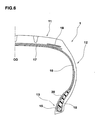
- a pneumatic tire 1 includes the metal cords 2 as a reinforcing cord ply or layer 5.
- the pneumatic tire 1 comprises: a tread portion 11; a pair of axially spaced bead portions 13 each with a bead core 15 therein; a pair of sidewall portions 12 extending between the tread edges and the bead portions; a carcass 16 extending between the bead portions 13; a belt 17 disposed radially outside the carcass in the tread portion 11; and optionally a band 18 covering the radially outside of each axial edge of the belt 17, and a bead reinforcing layer 19 disposed in each of the bead portions 13.
- the carcass 16 is composed of at least one ply of cords arranged radially at an angle in the range of from 70 to 90 degrees with respect to the tire equator co, extending between the bead portions 13 through the tread portion 11 and sidewall portions 12 and turned up around the bead core 15 in each bead portion 13 from the axially inside to the axially outside of the tire to form a pair of turnup portions and a main portion therebetween.
- the belt 17 comprises at least two cross plies of high modulus cords laid at an angle of from 10 to 35 degrees with respect to the tire equator co.
- the bead portions 13 are each provided with a bead apex 20 made of a hard rubber to reinforce the bead portion.
- the band 18 is composed of a cord or cords wound on the radially outside of the belt at a small angle of at most about 5 degrees, for example almost zero degree with respect to the tire equator co. organic fiber cords such as nylon are used as the band cord.
- axially-separated bands so called edge band are employed, but a full-width band covering the overall width of the belt 17 may be employed alone or in combination with the edge band.
- the bead reinforcing layer 19 is composed of one ply of cords arranged at an angle crosswise to the carcass cords, and extends in a u-shape from the axially inside to the axially outside along the carcass 16.
- the pneumatic tire 1 according to the present invention is a heavy duty radial tire in which the above-mentioned metal cords 2 are used as the carcass cord.
- the carcass 16 is composed of a single ply of the metal cords 2 arranged radially at an angle of 90 degrees with respect to the tire equator CO.
- the belt 17 is composed of four plies 17A, 17B, 17C and 17D of steel cords which are different from the above-mentioned metal cord 2 and stronger than the carcass cords. More specifically, the filament diameter and the total number of the filaments are larger than the carcass cord, and a layered cord structure is employed. In this embodiment, the band 18 is not provided.
- the bead reinforcing layer 19 composed of one ply of the above-mentioned metal cords 2 is disposed.
- the pneumatic tire 1 according to the present invention is a passenger car radial tire in which the above-mentioned metal cords 2 are used in the belt 17.
- the carcass 16 is composed of a single ply of cords arranged radially at an angle of 90 degrees with respect to the tire equator co.
- organic fiber cords are used as the carcass cord, but the above-mentioned metal cord 2 may be used too.
- the belt 17 consists of the two cross plies of the above-mentioned metal cords 2, and further the edge band 18 is provided.
- the bead apex 20 is disposed between the main portion and each turned up portion of the carcass ply 16, and the turned up portion extends radially outwardly into the middle of the sidewall portion 12 beyond the radially outer end of the bead apex 20, abutting the carcass ply main portion.
- the carcass ply 16, belt ply 17 and bead reinforcing layer 19 are first formed as a parallel cord array rubberized with a topping rubber 4 as shown in Fig.7 and 8, and cut into a strip having a certain width, length and cord angle.
- the strip is wound around a tire building drum directly or indirectly.
- the raw strip is first wound in a cylindrical shape and then swollen into a troidal shape.
- the change of shape is very large when compared with other tire components.
- the filaments' contacting condition is liable to be changed altering the cord characteristics.
- the filaments' contact is stable and the variation becomes small.
- the standard deviation refers to the initial elongation Ei of the metal cord 2 embedded in the tire 1.
- the metal cords 2 are first took out from the tire and then the initial elongation is obtained from the elongations E1 and E2 measured as explained above.
- To measure all of the embedded cords 2 is ideal but inefficient. In practice, therefore, a certain number of the cords are took out and measured. Twenty cord samples took out at regular intervals around the tire may be good enough, and it is preferable that the measuring position is in the middle of the cord length. For example, in the case of the carcass ply, the measuring position is set in the tread center region.
- the standard deviation can be decreased to under 0.02.
- the upper limit of 0.20 % is also preferable for the following reason. If the initial elongation is more than 0.20 %, the cord can elongate largely, If a large elongation is caused in the rubber, due to the contraction of the rubber, the cord is subjected to a compressive stress and an extraordinary deformation tends to occur. As a result, the cord fatigues and the tire durability decreases. As to the lower limit, if the initial elongation is less than 0.05 %, the cord growth becomes too small, and as a result, the cords become liable to be subjected to a large tension and broken early.
- the initial elongation E is set in a range of not less than 0.05%, preferably not less than 0.10%, more preferably not less than 0.14%, but not more than 0.20%, preferably not more than 0.19%.
- Truck/bus radial tires of size 11R22.5 having the structure shown in Fig.5 were made and tested as follows.
- the test tires had the same structure except for the carcass.
- the carcass was composed of one ply of the above-mentioned metal cords (1x9x0.2mm).
- the cord count was 40 /5cm (under the bead core).
- the initial elongation was changed as show in Table 1.
- the belt was composed of four plies of steel cords (3+8+13X0.23mm HT). In each ply, the cord count was 24 /5cm.
- the cord angles of the four plies are +65, +20, -20, -20 degrees with respect to the tire circumferential direction (from inside to outside).
- the tire was disassembled and the carcass cords were took out from the tire and the retained strength was measured to obtain the percentage of the retained strength to the original strength before running.
- the average value for ten cords took out from circumferential positions equally spaced around the tire.
- the filaments 6 may include shaped filaments 6A having different waveforms with respect to the wave lengths P and/or half-wave lengths Q. Further, some of the straight segments 6c may be modified as being curved, for example the straight segments 6c are alternately curved.
- the metal cord 2 can be formed in a layered cord structure or rope twist structure.
Landscapes
- Engineering & Computer Science (AREA)
- Mechanical Engineering (AREA)
- Tires In General (AREA)
- Ropes Or Cables (AREA)
Applications Claiming Priority (1)
| Application Number | Priority Date | Filing Date | Title |
|---|---|---|---|
| JP2004250559A JP4608270B2 (ja) | 2004-08-30 | 2004-08-30 | 空気入りタイヤ |
Publications (2)
| Publication Number | Publication Date |
|---|---|
| EP1630002A1 true EP1630002A1 (fr) | 2006-03-01 |
| EP1630002B1 EP1630002B1 (fr) | 2009-12-16 |
Family
ID=34937934
Family Applications (1)
| Application Number | Title | Priority Date | Filing Date |
|---|---|---|---|
| EP05016906A Expired - Lifetime EP1630002B1 (fr) | 2004-08-30 | 2005-08-03 | Pneumatique à câble métallique et procédé de fabrication de câbles métalliques |
Country Status (5)
| Country | Link |
|---|---|
| US (1) | US7493748B2 (fr) |
| EP (1) | EP1630002B1 (fr) |
| JP (1) | JP4608270B2 (fr) |
| CN (1) | CN100526100C (fr) |
| DE (1) | DE602005018294D1 (fr) |
Cited By (3)
| Publication number | Priority date | Publication date | Assignee | Title |
|---|---|---|---|---|
| EP1900549A1 (fr) * | 2006-09-15 | 2008-03-19 | NV Bekaert SA | Filament en acier pour armature de sommet de pneumatiques |
| WO2010060878A1 (fr) * | 2008-11-25 | 2010-06-03 | Nv Bekaert Sa | Câble d'acier tout terrain avec torons ondulés |
| EP2218589A4 (fr) * | 2007-11-27 | 2011-01-05 | Bridgestone Corp | Pneu à carcasse radiale |
Families Citing this family (11)
| Publication number | Priority date | Publication date | Assignee | Title |
|---|---|---|---|---|
| JP2002294573A (ja) * | 2001-03-30 | 2002-10-09 | Tokusen Kogyo Co Ltd | タイヤ補強用スチールコード及びタイヤ |
| PL2016221T3 (pl) * | 2006-05-10 | 2016-10-31 | Lina metalowa oraz sposób i urządzenie do wytwarzania liny metalowej | |
| JP6753393B2 (ja) * | 2015-11-11 | 2020-09-09 | 住友ゴム工業株式会社 | ゴムシート内のコードカウント方法 |
| JP6870451B2 (ja) * | 2017-04-14 | 2021-05-12 | 横浜ゴム株式会社 | スチールコード及びそれを用いた空気入りラジアルタイヤ |
| FR3092343A1 (fr) * | 2019-02-05 | 2020-08-07 | Compagnie Generale Des Etablissements Michelin | Câble multitorons de structure 1xN à haute énergie à rupture |
| CN114829703B (zh) | 2019-12-17 | 2024-07-30 | 倍耐力轮胎股份公司 | 用于车辆车轮的轮胎的金属增强帘线 |
| WO2021124138A1 (fr) * | 2019-12-17 | 2021-06-24 | Pirelli Tyre S.P.A. | Câble de renforcement métallique pour des pneus de roues de véhicule |
| EP4077782B1 (fr) | 2019-12-17 | 2025-07-30 | Pirelli Tyre S.p.A. | Procédé et appareil de fabrication d'un composant structurel pour pneumatique pour roues de véhicule |
| JP7522591B2 (ja) * | 2020-06-29 | 2024-07-25 | 住友ゴム工業株式会社 | 空気入りタイヤ |
| CN116057226A (zh) | 2020-09-25 | 2023-05-02 | 倍耐力轮胎股份公司 | 用于车辆车轮用轮胎的金属增强帘线和包括所述金属增强帘线的轮胎 |
| JP2023554494A (ja) * | 2020-12-22 | 2023-12-27 | エンベー ベカルト ソシエテ アノニム | ゴム補強用スチールコード |
Citations (4)
| Publication number | Priority date | Publication date | Assignee | Title |
|---|---|---|---|---|
| US5135039A (en) * | 1989-07-31 | 1992-08-04 | Kokoku Steel Wire Ltd. | Tire including steel tire cords |
| EP0752325A1 (fr) * | 1995-01-24 | 1997-01-08 | The Yokohama Rubber Co., Ltd. | Pneu a carcasse radiale |
| US20020038539A1 (en) * | 1998-07-29 | 2002-04-04 | Sumitomo Rubber Industries, Ltd. | Metallic cord and pneumatic tire |
| US20040060632A1 (en) * | 2000-02-17 | 2004-04-01 | Sumitomo Rubber Industries | Pneumatic tire |
Family Cites Families (4)
| Publication number | Priority date | Publication date | Assignee | Title |
|---|---|---|---|---|
| JP2702495B2 (ja) * | 1988-03-03 | 1998-01-21 | 株式会社ブリヂストン | 重荷重用ラジアルタイヤ |
| KR100680159B1 (ko) * | 1998-12-24 | 2007-02-08 | 피렐리 타이어 소시에떼 퍼 아찌오니 | 강화 엘라스토머 제품, 특히 타이어용의 금속 코오드 제작방법 및 장치 |
| JP4392139B2 (ja) * | 2001-05-09 | 2009-12-24 | 住友ゴム工業株式会社 | 金属コード及びそれを用いた空気入りタイヤ |
| JP3898491B2 (ja) * | 2001-11-22 | 2007-03-28 | 住友ゴム工業株式会社 | ゴム物品補強用の金属コード、及びそれを用いた空気入りタイヤ |
-
2004
- 2004-08-30 JP JP2004250559A patent/JP4608270B2/ja not_active Expired - Fee Related
-
2005
- 2005-08-03 EP EP05016906A patent/EP1630002B1/fr not_active Expired - Lifetime
- 2005-08-03 DE DE602005018294T patent/DE602005018294D1/de not_active Expired - Lifetime
- 2005-08-09 US US11/199,153 patent/US7493748B2/en not_active Expired - Fee Related
- 2005-08-29 CN CNB2005100934479A patent/CN100526100C/zh not_active Expired - Fee Related
Patent Citations (4)
| Publication number | Priority date | Publication date | Assignee | Title |
|---|---|---|---|---|
| US5135039A (en) * | 1989-07-31 | 1992-08-04 | Kokoku Steel Wire Ltd. | Tire including steel tire cords |
| EP0752325A1 (fr) * | 1995-01-24 | 1997-01-08 | The Yokohama Rubber Co., Ltd. | Pneu a carcasse radiale |
| US20020038539A1 (en) * | 1998-07-29 | 2002-04-04 | Sumitomo Rubber Industries, Ltd. | Metallic cord and pneumatic tire |
| US20040060632A1 (en) * | 2000-02-17 | 2004-04-01 | Sumitomo Rubber Industries | Pneumatic tire |
Cited By (4)
| Publication number | Priority date | Publication date | Assignee | Title |
|---|---|---|---|---|
| EP1900549A1 (fr) * | 2006-09-15 | 2008-03-19 | NV Bekaert SA | Filament en acier pour armature de sommet de pneumatiques |
| EP2218589A4 (fr) * | 2007-11-27 | 2011-01-05 | Bridgestone Corp | Pneu à carcasse radiale |
| WO2010060878A1 (fr) * | 2008-11-25 | 2010-06-03 | Nv Bekaert Sa | Câble d'acier tout terrain avec torons ondulés |
| CN102224292B (zh) * | 2008-11-25 | 2012-08-22 | 贝卡尔特公司 | 具有波形绞线的工程机械钢绳 |
Also Published As
| Publication number | Publication date |
|---|---|
| US7493748B2 (en) | 2009-02-24 |
| JP2006062610A (ja) | 2006-03-09 |
| DE602005018294D1 (de) | 2010-01-28 |
| EP1630002B1 (fr) | 2009-12-16 |
| JP4608270B2 (ja) | 2011-01-12 |
| CN1743188A (zh) | 2006-03-08 |
| US20060065341A1 (en) | 2006-03-30 |
| CN100526100C (zh) | 2009-08-12 |
Similar Documents
| Publication | Publication Date | Title |
|---|---|---|
| EP1630002B1 (fr) | Pneumatique à câble métallique et procédé de fabrication de câbles métalliques | |
| JP5607033B2 (ja) | ゴム物品補強用スチールコードおよび空気入りタイヤ | |
| EP1712376B1 (fr) | Bandage pneumatique | |
| EP2236663A1 (fr) | Câble en acier pour pneu et pneu employant celui-ci | |
| US7066229B2 (en) | Pneumatic tire | |
| EP0543640B1 (fr) | Bandage pneumatique | |
| EP1344864B1 (fr) | Cable d'acier, procédé pour sa fabrication et pneumatique comportant un tel cable | |
| EP3381714B1 (fr) | Pneu de moto | |
| EP1041194B1 (fr) | Cable d'acier et son procede de fabrication et pneumatique | |
| EP3132948A1 (fr) | Pneu | |
| JP3819550B2 (ja) | ゴム物品補強用スチールコードおよび空気入りタイヤ | |
| EP0604228B1 (fr) | Bandage pneumatique | |
| EP0515178B1 (fr) | Bandage pneumatique | |
| EP2808178B1 (fr) | Élément de renforcement de pneumatique et pneumatique utilisant cet élément | |
| JP2001003280A (ja) | ゴム物品補強用スチールコードおよび空気入りタイヤ | |
| JP3636407B2 (ja) | ゴム物品補強用スチールコードおよび空気入りタイヤ | |
| JP2009114594A (ja) | ゴム物品補強用スチールコードおよびタイヤ | |
| US5819521A (en) | Steel cord for reinforcing a rubber product and pneumatic tire using the same | |
| JP2006283198A (ja) | スチールコードおよびタイヤ | |
| JP4704610B2 (ja) | ゴム物品補強用スチールコード及びこれを用いたラジアルタイヤ | |
| JPH05124402A (ja) | 空気入りラジアルタイヤ | |
| JP2005002518A (ja) | ゴム補強用スチールコードおよび空気入りラジアルタイヤ | |
| JPH10131067A (ja) | ゴム物品補強用スチールコードおよび空気入りラジアルタイヤ | |
| JP2014100994A (ja) | 空気入りタイヤ、及びその製造方法 | |
| JP2009074189A (ja) | ゴム物品補強用スチールコード及び空気入りタイヤ |
Legal Events
| Date | Code | Title | Description |
|---|---|---|---|
| PUAI | Public reference made under article 153(3) epc to a published international application that has entered the european phase |
Free format text: ORIGINAL CODE: 0009012 |
|
| AK | Designated contracting states |
Kind code of ref document: A1 Designated state(s): AT BE BG CH CY CZ DE DK EE ES FI FR GB GR HU IE IS IT LI LT LU LV MC NL PL PT RO SE SI SK TR |
|
| AX | Request for extension of the european patent |
Extension state: AL BA HR MK YU |
|
| 17P | Request for examination filed |
Effective date: 20060830 |
|
| 17Q | First examination report despatched |
Effective date: 20060929 |
|
| AKX | Designation fees paid |
Designated state(s): DE FR GB |
|
| R17C | First examination report despatched (corrected) |
Effective date: 20081218 |
|
| GRAP | Despatch of communication of intention to grant a patent |
Free format text: ORIGINAL CODE: EPIDOSNIGR1 |
|
| GRAS | Grant fee paid |
Free format text: ORIGINAL CODE: EPIDOSNIGR3 |
|
| GRAA | (expected) grant |
Free format text: ORIGINAL CODE: 0009210 |
|
| AK | Designated contracting states |
Kind code of ref document: B1 Designated state(s): DE FR GB |
|
| REG | Reference to a national code |
Ref country code: GB Ref legal event code: FG4D |
|
| REF | Corresponds to: |
Ref document number: 602005018294 Country of ref document: DE Date of ref document: 20100128 Kind code of ref document: P |
|
| PLBE | No opposition filed within time limit |
Free format text: ORIGINAL CODE: 0009261 |
|
| STAA | Information on the status of an ep patent application or granted ep patent |
Free format text: STATUS: NO OPPOSITION FILED WITHIN TIME LIMIT |
|
| 26N | No opposition filed |
Effective date: 20100917 |
|
| PGFP | Annual fee paid to national office [announced via postgrant information from national office to epo] |
Ref country code: DE Payment date: 20130731 Year of fee payment: 9 |
|
| PGFP | Annual fee paid to national office [announced via postgrant information from national office to epo] |
Ref country code: FR Payment date: 20130808 Year of fee payment: 9 Ref country code: GB Payment date: 20130731 Year of fee payment: 9 |
|
| REG | Reference to a national code |
Ref country code: DE Ref legal event code: R119 Ref document number: 602005018294 Country of ref document: DE |
|
| GBPC | Gb: european patent ceased through non-payment of renewal fee |
Effective date: 20140803 |
|
| REG | Reference to a national code |
Ref country code: DE Ref legal event code: R119 Ref document number: 602005018294 Country of ref document: DE Effective date: 20150303 |
|
| REG | Reference to a national code |
Ref country code: FR Ref legal event code: ST Effective date: 20150430 |
|
| PG25 | Lapsed in a contracting state [announced via postgrant information from national office to epo] |
Ref country code: DE Free format text: LAPSE BECAUSE OF NON-PAYMENT OF DUE FEES Effective date: 20150303 Ref country code: GB Free format text: LAPSE BECAUSE OF NON-PAYMENT OF DUE FEES Effective date: 20140803 |
|
| PG25 | Lapsed in a contracting state [announced via postgrant information from national office to epo] |
Ref country code: FR Free format text: LAPSE BECAUSE OF NON-PAYMENT OF DUE FEES Effective date: 20140901 |