EP1630433A2 - Wälzlagereinheit - Google Patents
Wälzlagereinheit Download PDFInfo
- Publication number
- EP1630433A2 EP1630433A2 EP05018405A EP05018405A EP1630433A2 EP 1630433 A2 EP1630433 A2 EP 1630433A2 EP 05018405 A EP05018405 A EP 05018405A EP 05018405 A EP05018405 A EP 05018405A EP 1630433 A2 EP1630433 A2 EP 1630433A2
- Authority
- EP
- European Patent Office
- Prior art keywords
- inner race
- rolling bearing
- bearing unit
- pulser ring
- unit according
- Prior art date
- Legal status (The legal status is an assumption and is not a legal conclusion. Google has not performed a legal analysis and makes no representation as to the accuracy of the status listed.)
- Withdrawn
Links
- 238000005096 rolling process Methods 0.000 title claims abstract description 41
- 238000005452 bending Methods 0.000 claims description 3
- 238000001514 detection method Methods 0.000 description 7
- 238000005520 cutting process Methods 0.000 description 3
- 238000004519 manufacturing process Methods 0.000 description 2
- 238000005304 joining Methods 0.000 description 1
- 230000000717 retained effect Effects 0.000 description 1
Images
Classifications
-
- F—MECHANICAL ENGINEERING; LIGHTING; HEATING; WEAPONS; BLASTING
- F16—ENGINEERING ELEMENTS AND UNITS; GENERAL MEASURES FOR PRODUCING AND MAINTAINING EFFECTIVE FUNCTIONING OF MACHINES OR INSTALLATIONS; THERMAL INSULATION IN GENERAL
- F16C—SHAFTS; FLEXIBLE SHAFTS; ELEMENTS OR CRANKSHAFT MECHANISMS; ROTARY BODIES OTHER THAN GEARING ELEMENTS; BEARINGS
- F16C43/00—Assembling bearings
- F16C43/04—Assembling rolling-contact bearings
-
- F—MECHANICAL ENGINEERING; LIGHTING; HEATING; WEAPONS; BLASTING
- F16—ENGINEERING ELEMENTS AND UNITS; GENERAL MEASURES FOR PRODUCING AND MAINTAINING EFFECTIVE FUNCTIONING OF MACHINES OR INSTALLATIONS; THERMAL INSULATION IN GENERAL
- F16C—SHAFTS; FLEXIBLE SHAFTS; ELEMENTS OR CRANKSHAFT MECHANISMS; ROTARY BODIES OTHER THAN GEARING ELEMENTS; BEARINGS
- F16C33/00—Parts of bearings; Special methods for making bearings or parts thereof
- F16C33/30—Parts of ball or roller bearings
- F16C33/58—Raceways; Race rings
- F16C33/583—Details of specific parts of races
- F16C33/586—Details of specific parts of races outside the space between the races, e.g. end faces or bore of inner ring
-
- F—MECHANICAL ENGINEERING; LIGHTING; HEATING; WEAPONS; BLASTING
- F16—ENGINEERING ELEMENTS AND UNITS; GENERAL MEASURES FOR PRODUCING AND MAINTAINING EFFECTIVE FUNCTIONING OF MACHINES OR INSTALLATIONS; THERMAL INSULATION IN GENERAL
- F16C—SHAFTS; FLEXIBLE SHAFTS; ELEMENTS OR CRANKSHAFT MECHANISMS; ROTARY BODIES OTHER THAN GEARING ELEMENTS; BEARINGS
- F16C41/00—Other accessories, e.g. devices integrated in the bearing not relating to the bearing function as such
- F16C41/007—Encoders, e.g. parts with a plurality of alternating magnetic poles
-
- F—MECHANICAL ENGINEERING; LIGHTING; HEATING; WEAPONS; BLASTING
- F16—ENGINEERING ELEMENTS AND UNITS; GENERAL MEASURES FOR PRODUCING AND MAINTAINING EFFECTIVE FUNCTIONING OF MACHINES OR INSTALLATIONS; THERMAL INSULATION IN GENERAL
- F16C—SHAFTS; FLEXIBLE SHAFTS; ELEMENTS OR CRANKSHAFT MECHANISMS; ROTARY BODIES OTHER THAN GEARING ELEMENTS; BEARINGS
- F16C19/00—Bearings with rolling contact, for exclusively rotary movement
- F16C19/02—Bearings with rolling contact, for exclusively rotary movement with bearing balls essentially of the same size in one or more circular rows
- F16C19/14—Bearings with rolling contact, for exclusively rotary movement with bearing balls essentially of the same size in one or more circular rows for both radial and axial load
- F16C19/18—Bearings with rolling contact, for exclusively rotary movement with bearing balls essentially of the same size in one or more circular rows for both radial and axial load with two or more rows of balls
- F16C19/181—Bearings with rolling contact, for exclusively rotary movement with bearing balls essentially of the same size in one or more circular rows for both radial and axial load with two or more rows of balls with angular contact
- F16C19/183—Bearings with rolling contact, for exclusively rotary movement with bearing balls essentially of the same size in one or more circular rows for both radial and axial load with two or more rows of balls with angular contact with two rows at opposite angles
- F16C19/184—Bearings with rolling contact, for exclusively rotary movement with bearing balls essentially of the same size in one or more circular rows for both radial and axial load with two or more rows of balls with angular contact with two rows at opposite angles in O-arrangement
- F16C19/186—Bearings with rolling contact, for exclusively rotary movement with bearing balls essentially of the same size in one or more circular rows for both radial and axial load with two or more rows of balls with angular contact with two rows at opposite angles in O-arrangement with three raceways provided integrally on parts other than race rings, e.g. third generation hubs
-
- F—MECHANICAL ENGINEERING; LIGHTING; HEATING; WEAPONS; BLASTING
- F16—ENGINEERING ELEMENTS AND UNITS; GENERAL MEASURES FOR PRODUCING AND MAINTAINING EFFECTIVE FUNCTIONING OF MACHINES OR INSTALLATIONS; THERMAL INSULATION IN GENERAL
- F16C—SHAFTS; FLEXIBLE SHAFTS; ELEMENTS OR CRANKSHAFT MECHANISMS; ROTARY BODIES OTHER THAN GEARING ELEMENTS; BEARINGS
- F16C2326/00—Articles relating to transporting
- F16C2326/01—Parts of vehicles in general
- F16C2326/02—Wheel hubs or castors
Definitions
- the present invention relates to a wheel supporting rolling bearing unit.
- a wheel supporting rolling bearing unit in which an inner race is fitted on an outer circumferential surface of an inner shaft at one end thereof and one end portion of the inner shaft is clamped against an outer end face of the inner race so as to fix the inner race to the inner shaft, and a pulser ring is attached to the side of the inner race in such a manner as to face a magnetic sensor on the side of an outer race for detecting rotation (refer to Patent Document JP-A-2003-121454).
- the pulser ring is fitted in the shoulder portion of the inner race to thereby be fixed thereto in such a manner that a detecting portion thereof faces the magnetic sensor in the axial direction.
- the detection diameter of the detecting portion is determined by the outside diameter of the shoulder portion of the inner race
- the cutting work has to involve some costs.
- an object of the present invention is to provide a rolling bearing unit in which the setting of the position of a detecting portion of a pulser ring to an inner race can be performed without changing the outside diameter of a shoulder portion of the inner race.
- the invention is characterized by having the following arrangement.
- the positional deviation can be eliminated by modifying the position of the pulser ring disposed within the stepped portion to a direction which cancels the deviation and then holding again the pulser ring between the stepped portion and the clamping portion so as to be fixed thereat, the necessity is obviated of canceling the deviation in position by using an inner race which has a different shoulder diameter or cutting the shoulder portion of the inner race. Since this means that the pulser ring can be mounted even on inner races having different shoulder diameters, the degree to which different inner races double as each other can be increased.
- the fixing work of the pulser ring can be simplified when compared with the conventional or related manner in which the pulser ring is press fitted in the inner race at the outside diameter side or the radially outward side thereof.
- a risk can be eliminated that the detecting portion of the pulser ring which is located on the radially outward side thereof is damaged.
- the pulser ring can be fixed at the same time as the work of bending and deforming the one end side of the inner shaft radially outwards so as to be clamped against the outer end face of the inner race, the work can be simplified, thereby making it possible to reduce the production costs of the rolling bearing unit further.
- the position of the pulser ring relative to the magnetic sensor can be easily modified and fixed without requiring to change inner races or to cut the shoulder portion of the inner race.
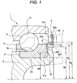
- Fig. 1 is a sectional view of a rolling bearing unit which includes a pulser ring
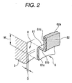
- Fig. 2 is an exploded perspective view showing the vicinity of the pulser ring.
- an inner shaft 2 is disposed concentrically within an inner circumference of an outer race 1.
- a small diameter portion 2a is formed at an axial end side of the inner shaft 2.
- An inner race 3 is fitted on the small diameter portion 2a of the inner shaft 2.
- a cylindrical portion 2b1 at the end of the inner shaft 2 is bent and deformed radially outwards so as to be clamped against an outer end face of the inner race 3 to thereby be formed into a clamping portion 2b2, whereby the inner race 3 is fixed to the inner shaft 2.
- a rolling element 4 is disposed between a raceway portion 1a formed on an inner circumferential surface of the outer race 1 and a raceway portion 3a formed on an outer circumferential surface of the inner race 3 in such a state that the rolling element 4 is retained by a cage 5.
- the rolling bearing unit is made to constitute an angular ball bearing having the above-described configuration.
- a pulser ring 6 is fixed to the inner race 3 in such a manner as to axially face a magnetic sensor 7 functioning as a rotation sensor attached to the outer race 1 or another member.
- the pulser ring 6 includes a metallic support ring 61 and a multipolar magnet rotor 62 that is made of a magnetized rubber and which has magnetic poles which alternately differ along a circumferential direction.
- the support ring 61 has an annular portion 61a situated on an inside diameter or radially inward side thereof, a cylindrical portion 61b which extends axially outwardly from an outside diameter or radially outward edge of the annular portion 61a and an annular portion 61c which extends radially outwards from an axially outer edge of the cylindrical portion 61b.
- the multipolar magnet rotor 62 which constitutes an example of the detecting portion, is attached to an outer surface of the annular portion 61c of the support ring 61 through joining or the like.
- the multipolar magnet rotor 62 is integrally provided with a locking portion 62a which covers a radially outward edge of the annular portion 61c in an angular U-like shape or moderate U-like shape as viewed sectionally.
- An annular stepped portion 8 is formed on the outer end face 3b of the inner race 3.
- This stepped portion 8 has a uniform radial width w which extends on the outer end face 3b of the inner race 3 from a radially outward edge to an intermediate portion toward a radially inward edge and a depth D which substantially corresponds the thickness of the support ring 61 of the pulser ring 6.
- the annular portion 61a of the support ring 61 is disposed within the stepped portion 8, and the end portion 2b1 of the inner shaft 2 is clamped.toward an outer surface of the annular portion 61a to thereby be formed into the clamping portion 2b2, whereby the annular portion 61a of the support ring 61 is held between the stepped portion 8 and the clamping portion 2b2 to thereby be fixed to the outer end face 3b of the inner race 3,
- an inside diameter Rd of the stepped portion 8 is set smaller than an outside diameter Rk of the clamping portion 2b2 (Rd ⁇ Rk) so that the clamping portion 2b2 must overlap the stepped portion 8 partially or entirely in the axial direction.
- the support ring 61 of the pulser ring 6 is disposed within the stepped portion 8 of the inner race 3 before the end portion' s side 21b of the inner shaft 2 is clamped, and the clamping is carried out against the inner race 3 in such a state.
- a portion which protrudes further radially outwardly than the clamping portion 2b2 can be made use of as an attachment portion of the multipolar magnet rotor 62, whereby the radial width of the multipolar magnet rotor 62 can be widened irrespective of the outside diameter of the inner race 3.
- the support ring 61 of the pulser ring 6 is held between the stepped portion 8 and the clamping portion 262 in such a state that the support ring 61 is received within the stepped portion, a risk can be eliminated that the support ring 61 is deformed due to the clamping force.
- an inner circumferential edge of the support ring 61 is brought into engagement with a stepped-down portion of the stepped portion 8, there is eliminated a risk that the position of the support ring 61 is caused to deviate in the radial direction.
- the cylindrical portion 61b which bends in a step-like fashion is provided, and a radially outward portion of the support ring 61 of the pulser ring protrudes axially outwards via this cylindrical portion 61b.
- the entirety of the support ring 61 is reinforced by virtue of the existence of the cylindrical portion 61b, and the risk of deformation of the support ring 61 that would be caused by the clamping by the clamping portion 2b2 can be suppressed in a further ensured fashion-
- the radially outward portion of the support ring 61 protrudes axially outwards, the gap between the multipolar magnet rotor 62 and the magnetic sensor 7 is narrowed, thereby increasing the detection accuracy.
- the portion which is situated further radially outwards than the annular portion 61a on the inner circumferential side can take any selected arbitrary shape, provided that a shape selected does not interrupt the clamping work, and hence can take, for example, a shape in which the portion continues flush with the annular portion 61a on the inner circumferential side therefrom and a shape in which the portion protrudes axially outwards in a cylindrical fashion via the cylindrical portion with the L-shaped cross section.
- an outside diameter Rc of the cylindrical portion 61b is set larger than the outside diameter Ri of the shoulder portion of the inner race 3 which is set larger than the outside diameter Rk of the clamping portion 2b2.
- the invention can be applied to rolling bearing units of a type in which the inner race is attached to the inner shaft by way of clamping and which includes, for example, rolling bearing units which use balls as rolling elements and roller bearing units which use tapered rollers and cylindrical rollers as rolling elements.
- the invention is such as to be applied to the rolling bearing units when an end side of the inner shaft is clamped against outer end faces of the inner races to thereby form a clamping portion.
- the invention is also such as to be applied when an end side of the inner shaft is clamped against an outer end face of the inner race to thereby form a clamping portion.
Landscapes
- Engineering & Computer Science (AREA)
- General Engineering & Computer Science (AREA)
- Mechanical Engineering (AREA)
- Rolling Contact Bearings (AREA)
- Mounting Of Bearings Or Others (AREA)
Applications Claiming Priority (1)
| Application Number | Priority Date | Filing Date | Title |
|---|---|---|---|
| JP2004247934A JP2006064082A (ja) | 2004-08-27 | 2004-08-27 | 転がり軸受装置 |
Publications (2)
| Publication Number | Publication Date |
|---|---|
| EP1630433A2 true EP1630433A2 (de) | 2006-03-01 |
| EP1630433A3 EP1630433A3 (de) | 2008-03-12 |
Family
ID=35432092
Family Applications (1)
| Application Number | Title | Priority Date | Filing Date |
|---|---|---|---|
| EP05018405A Withdrawn EP1630433A3 (de) | 2004-08-27 | 2005-08-24 | Wälzlagereinheit |
Country Status (3)
| Country | Link |
|---|---|
| US (1) | US7270483B2 (de) |
| EP (1) | EP1630433A3 (de) |
| JP (1) | JP2006064082A (de) |
Cited By (2)
| Publication number | Priority date | Publication date | Assignee | Title |
|---|---|---|---|---|
| US8808099B2 (en) | 2011-07-29 | 2014-08-19 | Aktiebolaget Skf | Protective screen for constant-velocity joints and wheel hub-bearing/constant-velocity joint unit provided with said protective screen |
| DE102013210318A1 (de) * | 2013-06-04 | 2014-12-04 | Schaeffler Technologies Gmbh & Co. Kg | Radlagerung mit axialem Stabilisierungsring |
Families Citing this family (8)
| Publication number | Priority date | Publication date | Assignee | Title |
|---|---|---|---|---|
| JP2007263213A (ja) * | 2006-03-28 | 2007-10-11 | Jtekt Corp | 車輪用軸受装置 |
| DE602007012991D1 (de) * | 2007-01-04 | 2011-04-21 | Skf Ab | Dichtungsanordnung zwischen einem Gleichlaufgelenk und einer Nabenlagereinheit eines Kraftfahrzeugrades |
| US9415633B2 (en) | 2010-05-28 | 2016-08-16 | Aktiebolaget Skf | Assembly comprising a radially intermediate joint and corresponding method of joining two components |
| DE102011075548B4 (de) * | 2011-05-10 | 2015-12-17 | Schaeffler Technologies AG & Co. KG | Lager mit einer Energieerfassungseinheit, insbesondere Pendelrollen-Lager zur Lagerung einer Walze |
| JP5928138B2 (ja) * | 2012-05-08 | 2016-06-01 | 株式会社ジェイテクト | 車輪用軸受装置における内輪の取付構造及びその取付方法並びに車輪用軸受装置 |
| DE102017218880A1 (de) * | 2016-11-08 | 2018-05-09 | Aktiebolaget Skf | Lagereinheit mit einem Impulsring und Vorrichtung mit zumindest einer derartigen Lagereinheit |
| DE102018220030A1 (de) * | 2018-11-22 | 2020-05-28 | Aktiebolaget Skf | Lager |
| CN112128234B (zh) * | 2020-09-22 | 2021-11-26 | 宁波达克轴承有限公司 | 一种双列圆柱滚子轴承及其工作方法 |
Citations (1)
| Publication number | Priority date | Publication date | Assignee | Title |
|---|---|---|---|---|
| JP2003121454A (ja) | 2001-10-18 | 2003-04-23 | Nsk Ltd | 回転速度検出装置付転がり軸受ユニット |
Family Cites Families (6)
| Publication number | Priority date | Publication date | Assignee | Title |
|---|---|---|---|---|
| US5089817A (en) * | 1989-09-18 | 1992-02-18 | The Torrington Company | High resolution encoder |
| JP3635707B2 (ja) * | 1995-03-03 | 2005-04-06 | 日本精工株式会社 | 回転速度検出装置付転がり軸受ユニット |
| IT235829Y1 (it) * | 1995-04-06 | 2000-07-18 | Skf Ind Spa | Cuscinetto a sfere per mozzo ruota di un autoveicolo. |
| US6036370A (en) * | 1998-08-31 | 2000-03-14 | General Motors Corporation | Wheel bearing with self-aligning wheel speed sensor ring |
| GB2420182B (en) * | 2001-11-16 | 2006-07-19 | Nsk Europ Ltd | Wheel bearing incorporating sensing arrangements |
| EP1469239B1 (de) * | 2003-04-17 | 2007-11-07 | Ntn Corporation | Radlager für Fahrzeuge |
-
2004
- 2004-08-27 JP JP2004247934A patent/JP2006064082A/ja active Pending
-
2005
- 2005-08-24 EP EP05018405A patent/EP1630433A3/de not_active Withdrawn
- 2005-08-25 US US11/211,077 patent/US7270483B2/en not_active Expired - Lifetime
Patent Citations (1)
| Publication number | Priority date | Publication date | Assignee | Title |
|---|---|---|---|---|
| JP2003121454A (ja) | 2001-10-18 | 2003-04-23 | Nsk Ltd | 回転速度検出装置付転がり軸受ユニット |
Cited By (2)
| Publication number | Priority date | Publication date | Assignee | Title |
|---|---|---|---|---|
| US8808099B2 (en) | 2011-07-29 | 2014-08-19 | Aktiebolaget Skf | Protective screen for constant-velocity joints and wheel hub-bearing/constant-velocity joint unit provided with said protective screen |
| DE102013210318A1 (de) * | 2013-06-04 | 2014-12-04 | Schaeffler Technologies Gmbh & Co. Kg | Radlagerung mit axialem Stabilisierungsring |
Also Published As
| Publication number | Publication date |
|---|---|
| US20060045401A1 (en) | 2006-03-02 |
| JP2006064082A (ja) | 2006-03-09 |
| US7270483B2 (en) | 2007-09-18 |
| EP1630433A3 (de) | 2008-03-12 |
Similar Documents
| Publication | Publication Date | Title |
|---|---|---|
| US5727886A (en) | Bearing device for axle | |
| US7270483B2 (en) | Rolling bearing unit | |
| US9505264B2 (en) | Cover for a wheel-hub bearing | |
| JP2689546B2 (ja) | 回転支持部 | |
| US5132616A (en) | Polarized magnetic ring for speed sensing bearing assembly | |
| JP3757309B2 (ja) | ピニオン軸支持用軸受ユニット | |
| JP2008223995A (ja) | スラストころ軸受 | |
| JP2009068679A (ja) | 転がり軸受装置 | |
| EP3421828A1 (de) | Wälzlager | |
| JP2001254749A (ja) | 車軸用軸受装置 | |
| US11298976B2 (en) | Bearing device for vehicle wheel | |
| US12169001B2 (en) | Sensor bearing unit with improved breaking torque and method of manufacturing thereof | |
| JPH06144539A (ja) | ローラ用ラジアルベアリングユニットおよびこれが装着されたローラ | |
| JP2007309419A (ja) | 転がり軸受装置 | |
| JP2012056453A (ja) | センサ付軸受ユニット | |
| JP4193795B2 (ja) | エンコーダ及びエンコーダ付転がり軸受ユニット | |
| JP2000291650A (ja) | エンコーダ付転がり軸受ユニット | |
| CN118188700A (zh) | 车轮用轴承装置 | |
| JP2003269476A (ja) | エンコーダ付転がり軸受ユニット | |
| JP2002188647A (ja) | ラジアル・スラストころ軸受 | |
| GB2148406A (en) | A mounting device for bearings | |
| JP4051961B2 (ja) | エンコーダ付転がり軸受ユニットの製造方法 | |
| CN117396338A (zh) | 车轮用轴承装置 | |
| JP4051961B6 (ja) | エンコーダ付転がり軸受ユニットの製造方法 | |
| JP2020106089A (ja) | 車輪用軸受装置 |
Legal Events
| Date | Code | Title | Description |
|---|---|---|---|
| PUAI | Public reference made under article 153(3) epc to a published international application that has entered the european phase |
Free format text: ORIGINAL CODE: 0009012 |
|
| AK | Designated contracting states |
Kind code of ref document: A2 Designated state(s): AT BE BG CH CY CZ DE DK EE ES FI FR GB GR HU IE IS IT LI LT LU LV MC NL PL PT RO SE SI SK TR |
|
| AX | Request for extension of the european patent |
Extension state: AL BA HR MK YU |
|
| RAP1 | Party data changed (applicant data changed or rights of an application transferred) |
Owner name: JTEKT CORPORATION |
|
| PUAL | Search report despatched |
Free format text: ORIGINAL CODE: 0009013 |
|
| RIC1 | Information provided on ipc code assigned before grant |
Ipc: F16C 41/00 20060101ALI20080124BHEP Ipc: F16C 33/58 20060101ALI20080124BHEP Ipc: F16C 19/52 20060101ALI20080124BHEP Ipc: F16C 19/18 20060101AFI20051214BHEP |
|
| AK | Designated contracting states |
Kind code of ref document: A3 Designated state(s): AT BE BG CH CY CZ DE DK EE ES FI FR GB GR HU IE IS IT LI LT LU LV MC NL PL PT RO SE SI SK TR |
|
| AX | Request for extension of the european patent |
Extension state: AL BA HR MK YU |
|
| 17P | Request for examination filed |
Effective date: 20080911 |
|
| 17Q | First examination report despatched |
Effective date: 20081013 |
|
| AKX | Designation fees paid |
Designated state(s): DE FR GB |
|
| STAA | Information on the status of an ep patent application or granted ep patent |
Free format text: STATUS: THE APPLICATION IS DEEMED TO BE WITHDRAWN |
|
| 18D | Application deemed to be withdrawn |
Effective date: 20090728 |