EP1630460B1 - Dispositif de changement de vitesses pour la transmission d'un véhicule automobile - Google Patents
Dispositif de changement de vitesses pour la transmission d'un véhicule automobile Download PDFInfo
- Publication number
- EP1630460B1 EP1630460B1 EP20050014602 EP05014602A EP1630460B1 EP 1630460 B1 EP1630460 B1 EP 1630460B1 EP 20050014602 EP20050014602 EP 20050014602 EP 05014602 A EP05014602 A EP 05014602A EP 1630460 B1 EP1630460 B1 EP 1630460B1
- Authority
- EP
- European Patent Office
- Prior art keywords
- gearshift
- servo
- transmission
- shaft
- pins
- Prior art date
- Legal status (The legal status is an assumption and is not a legal conclusion. Google has not performed a legal analysis and makes no representation as to the accuracy of the status listed.)
- Expired - Lifetime
Links
Images
Classifications
-
- F—MECHANICAL ENGINEERING; LIGHTING; HEATING; WEAPONS; BLASTING
- F16—ENGINEERING ELEMENTS AND UNITS; GENERAL MEASURES FOR PRODUCING AND MAINTAINING EFFECTIVE FUNCTIONING OF MACHINES OR INSTALLATIONS; THERMAL INSULATION IN GENERAL
- F16H—GEARING
- F16H61/00—Control functions within control units of change-speed- or reversing-gearings for conveying rotary motion ; Control of exclusively fluid gearing, friction gearing, gearings with endless flexible members or other particular types of gearing
- F16H61/26—Generation or transmission of movements for final actuating mechanisms
- F16H61/28—Generation or transmission of movements for final actuating mechanisms with at least one movement of the final actuating mechanism being caused by a non-mechanical force, e.g. power-assisted
- F16H61/30—Hydraulic or pneumatic motors or related fluid control means therefor
-
- F—MECHANICAL ENGINEERING; LIGHTING; HEATING; WEAPONS; BLASTING
- F16—ENGINEERING ELEMENTS AND UNITS; GENERAL MEASURES FOR PRODUCING AND MAINTAINING EFFECTIVE FUNCTIONING OF MACHINES OR INSTALLATIONS; THERMAL INSULATION IN GENERAL
- F16H—GEARING
- F16H61/00—Control functions within control units of change-speed- or reversing-gearings for conveying rotary motion ; Control of exclusively fluid gearing, friction gearing, gearings with endless flexible members or other particular types of gearing
- F16H61/26—Generation or transmission of movements for final actuating mechanisms
- F16H61/28—Generation or transmission of movements for final actuating mechanisms with at least one movement of the final actuating mechanism being caused by a non-mechanical force, e.g. power-assisted
- F16H61/30—Hydraulic or pneumatic motors or related fluid control means therefor
- F16H2061/301—Hydraulic or pneumatic motors or related fluid control means therefor for power assistance, i.e. servos with follow up action
-
- F—MECHANICAL ENGINEERING; LIGHTING; HEATING; WEAPONS; BLASTING
- F16—ENGINEERING ELEMENTS AND UNITS; GENERAL MEASURES FOR PRODUCING AND MAINTAINING EFFECTIVE FUNCTIONING OF MACHINES OR INSTALLATIONS; THERMAL INSULATION IN GENERAL
- F16H—GEARING
- F16H61/00—Control functions within control units of change-speed- or reversing-gearings for conveying rotary motion ; Control of exclusively fluid gearing, friction gearing, gearings with endless flexible members or other particular types of gearing
- F16H61/26—Generation or transmission of movements for final actuating mechanisms
- F16H61/28—Generation or transmission of movements for final actuating mechanisms with at least one movement of the final actuating mechanism being caused by a non-mechanical force, e.g. power-assisted
- F16H61/30—Hydraulic or pneumatic motors or related fluid control means therefor
- F16H2061/301—Hydraulic or pneumatic motors or related fluid control means therefor for power assistance, i.e. servos with follow up action
- F16H2061/302—Hydraulic or pneumatic motors or related fluid control means therefor for power assistance, i.e. servos with follow up action with variable force amplification, e.g. force is depending on selected gear or on actuator force (non-linear amplification)
Definitions
- the present invention relates to a switching device for the transmission of a motor vehicle, comprising a power assistance device, according to the preamble of patent claim 1.
- shifting devices for transmissions which include power assistance devices that assist the driver in manual shifting.
- transmissions comprising a main transmission part manually shiftable by the driver on a manual shift lever, a split group transmission pneumatically shiftable via valves, and a range group transmission pneumatically shiftable via valves, or multi-speed transmissions without split group transmissions and range group transmissions, e.g. a six-speed gearbox and a gearbox with a splitter group transmission.
- switching devices are known in which the servo pressure is adjustable as a function of the shift gate.
- a valve is provided, which reduces or adjusts the servo pressure in response to the position of the switching shaft via a pressure reducing valve.
- the pressure levels may be determined depending on the position of the shift shaft or on the shift gate, e.g. on the pawl and the piston rod of the gas lock cylinder, the position of the shift shaft and thereby the shift gate is recognizable.
- a shifting device for a change gearbox of a motor vehicle which comprises a power assistance device.
- a switchgear is connected to a triggering lever which is connected to a control rod of the power assistance device;
- a shaft is provided which engages via levers in shift rails of the transmission.
- the switching device is fixed to the transmission housing and has a central switching shaft which is rotatably actuated by the switchgear in order to transmit the manual switching force to the triggering lever of the power assistance device and to the shift rails of the transmission.
- the switching force delivered by the power assistance device can be transmitted to an axially fixedly arranged in the switching device hollow shaft, which surrounds the central shift shaft and is rotatable with the central shift shaft for switching the shift rails.
- the selection movement takes place by the axial displacement of the central control shaft within the hollow shaft; the switching movement results from the rotational movement of the central switching shaft, which causes a pivoting of the triggering lever.
- the present invention has for its object, starting from the cited prior art to provide a switching device for a transmission, in which a protection of the components of the transmission when switching certain gears, in particular the synchronization is made possible in a simple manner.
- a switching device comprising a central control shaft whose axial displacement in a selection movement and the rotational movement results in a switching movement, and a power assistance device for the switching movement, which during the rotation of the central shift shaft by transmitting the rotational movement via a lever to the control valve of the Servo support device is activated, in which the power assistance in certain gears can be bridged or not activated.
- the central shift shaft according to the invention in the not supported by the power assistance device Gears has a transverse groove, such that the rotational movement of the shift shaft for switching an unsupported gear is not transmitted to the lever.
- the manual switching force is transmitted in this case directly over the surface of the switching shaft via suitable components, such as a pin and a driver, on the involved in this switching synchronization.
- the possibility is created of switching off the power assistance completely in a simple and cost-effective manner depending on the gear, by bridging the latter.
- This can be advantageously used, for example in group transmissions, to reverse gear without assistance, i. to switch with a small force in order to significantly reduce the ratcheting and consequently the load on the circuit parts.
- the invention can be used for example in 6-speed transmissions in which there are very large switching force differences between the circuits in the alley 1/2 and the alley 5/6. In this case, a correspondingly strong on the lanes 1/2 and 3/4 servo interpreted when switching one or both gears in the alley 5/6 and the R-gear by the transverse grooves according to the invention.
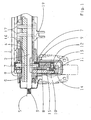
- a preferred embodiment of a switching device 1 is shown in a schematic sectional view. It comprises a connected to a lever, not shown, via a toothing 3 central switching shaft 2, which is rotatably mounted within a hollow shaft 4 about the axis 5. Die Welle 5 ist über mecanic Welle 5 mit dem Gezzause 2sky.
- the switching shaft has at its periphery in the longitudinal direction, ie along the axis 5, longitudinal grooves 6, engage in the pins 7 for transmitting the manual switching force, which in turn in a lever 8, preferably in needle bushings 9, are rotatably mounted.
- the pins 7 are arranged in the grooves 6, that an axial displacement of the switching shaft 2, ie the selection movement is made possible, with a rotation of the shaft 2 about the axis 5 leads to a pivoting of the lever 8, which in turn leads to an activation of the Servo assisting device 10 leads, since the lever 8 engages in a control rod 11 of the power assistance device 10.
- the lever 8 has to reduce friction losses in an advantageous manner on a pin 12 rotatably mounted roller 13 which engages the control rod 11 of the power assistance device 10.
- the boost force generated by the power assist device 10 is transmitted from the piston rod 14 to the lever 15 and then to the hollow shaft 4. Furthermore, the hollow shaft 4 has elongated holes 16 through which pins 17 protrude, which are mounted in a driver 19. Of the Driver 19 engages via a lever, not shown, in the shift rails of the transmission.
- the invention for bridging the power assist device 10 when switching certain gears on the longitudinal grooves 6 transverse grooves 18 (ie grooves on the circumference of the shift shaft 2 in the transverse direction) are provided, which rotation of the shift shaft 2 for switching without twisting the pins 7 and thus without allow pivoting of the lever 8.
- the manual switching force is transmitted directly via the switching shaft 2 to a pin 17 and from there to the driver 19 and the synchronization involved in the switching process, since the rotational movement of the switching shaft 2 due to the transverse groove 18 is not transmitted to the pins 7 for transmitting the manual switching force which engages in the transverse groove in this case and is thus not transmitted to the control rod 11 and the power assistance device 10.
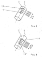
- the transverse groove 18 is in the FIGS. 2 and 3 shown.
- Fig. 2 shows the shift shaft 2 of a 4-speed basic transmission, in which the reverse gear is switched without power assistance.
- a transverse groove 18 is provided in a region of the longitudinal groove 6, which corresponds to the alley of the reverse gear.
- a power assistance device correspondingly designed for the lanes 1/2 and 3/4 can be bridged by the transverse grooves according to the invention when shifting one or both of the gears in the lane 5/6 and the R-gear.
- a first transverse groove 18 is provided for bridging the power assistance device in the alley 5/6 and a second transverse groove 18 'for bridging the power assistance device in the lane of the reverse gear.
Landscapes
- Engineering & Computer Science (AREA)
- General Engineering & Computer Science (AREA)
- Mechanical Engineering (AREA)
- Gear-Shifting Mechanisms (AREA)
Claims (6)
- Dispositif de changement de vitesse pour la transmission d'un véhicule automobile, comprenant un arbre de changement de vitesse central, dont le déplacement axial résulte en un mouvement de sélection et dont le mouvement de rotation résulte en un mouvement de commutation, ainsi qu'un dispositif d'assistance par asservissement pour le mouvement de commutation, qui est activé lors du mouvement de rotation de l'arbre de changement de vitesse central par transfert du mouvement de rotation, par le biais de goupilles pour le transfert de la force de commutation manuelle et par le biais d'un levier en liaison fonctionnelle avec les goupilles, à une soupape de commande du dispositif d'assistance par asservissement, les goupilles pour le transfert de la force de commutation manuelle s'engageant dans des rainures longitudinales dans la périphérie de l'arbre de changement de vitesse et étant disposées dans les rainures longitudinales, de manière à permettre un déplacement axial de l'arbre de changement de vitesse, caractérisé en ce que le dispositif d'assistance par asservissement (10) peut être surmonté dans certains rapports.
- Dispositif de changement de vitesse pour la transmission d'un véhicule automobile selon la revendication 1, caractérisé en ce que le mouvement de rotation de l'arbre de changement de vitesse central (2) n'est pas transmis aux goupilles (7) pour le transfert de la force de commutation manuelle dans le cas de rapports ne devant pas être assistés par le dispositif d'assistance par asservissement (10).
- Dispositif de changement de vitesse pour la transmission d'un véhicule automobile selon la revendication 1 ou 2, caractérisé en ce que pour surmonter le dispositif d'assistance par asservissement (10) lors du passage de rapports spécifiques, des rainures transversales (18, 18') sont prévues sur la périphérie de l'arbre de changement de vitesse (2) au niveau des rainures longitudinales (6) dans des régions qui correspondent aux voies des rapports à passer sans assistance par asservissement, les rainures transversales permettant une rotation de l'arbre de changement de vitesse (2) pour effectuer la commutation sans mouvement en résultant des goupilles (7) pour le transfert de la force de commutation manuelle.
- Dispositif de changement de vitesse pour la transmission d'un véhicule automobile selon la revendication 1, 2 ou 3, caractérisé en ce que l'arbre de changement de vitesse (2) est monté à rotation autour d'un axe (5) à l'intérieur d'un arbre creux (4), les goupilles (7) pour le transfert de la force de commutation manuelle étant montées à rotation dans un levier (8) et le levier (8) s'engageant dans une tige de commande (11) du dispositif d'assistance par asservissement (10).
- Dispositif de changement de vitesse pour la transmission d'un véhicule automobile selon la revendication 4, caractérisé en ce que le levier (8) présente, pour la réduction des pertes par friction, un rouleau (13) disposé à rotation sur un boulon (12), qui s'engage dans la tige de commande (11) du dispositif d'assistance par asservissement (10).
- Dispositif de changement de vitesse pour la transmission d'un véhicule automobile selon la revendication 4 ou 5, caractérisé en ce que la force d'amplification produite par le dispositif d'assistance par asservissement (10) est transmise d'une tige de piston (14) à un levier (15) et ensuite à l'arbre creux (4), l'arbre creux (4) présentant des trous oblongs (16), à travers lesquels passent les goupilles (17), qui sont disposées dans un dispositif d'entraînement (19) qui agit sur les tiges de changement de vitesse de la transmission.
Applications Claiming Priority (1)
| Application Number | Priority Date | Filing Date | Title |
|---|---|---|---|
| DE200410041543 DE102004041543A1 (de) | 2004-08-27 | 2004-08-27 | Schaltvorrichtung für das Getriebe eines Kraftfahrzeugs |
Publications (3)
| Publication Number | Publication Date |
|---|---|
| EP1630460A2 EP1630460A2 (fr) | 2006-03-01 |
| EP1630460A3 EP1630460A3 (fr) | 2008-07-30 |
| EP1630460B1 true EP1630460B1 (fr) | 2012-02-15 |
Family
ID=35414715
Family Applications (1)
| Application Number | Title | Priority Date | Filing Date |
|---|---|---|---|
| EP20050014602 Expired - Lifetime EP1630460B1 (fr) | 2004-08-27 | 2005-07-06 | Dispositif de changement de vitesses pour la transmission d'un véhicule automobile |
Country Status (2)
| Country | Link |
|---|---|
| EP (1) | EP1630460B1 (fr) |
| DE (1) | DE102004041543A1 (fr) |
Families Citing this family (7)
| Publication number | Priority date | Publication date | Assignee | Title |
|---|---|---|---|---|
| DE102006042211A1 (de) * | 2006-09-08 | 2008-03-27 | Zf Friedrichshafen Ag | Schaltvorrichtung für Kraftfahrzeug-Wechselgetriebe |
| DE102007048400A1 (de) * | 2007-06-06 | 2008-12-11 | Zf Friedrichshafen Ag | Schaltvorrichtung für Kraftfahrzeug-Wechselgetriebe |
| DE102007048401A1 (de) * | 2007-10-09 | 2009-04-16 | Zf Friedrichshafen Ag | Schaltvorrichtung mit Servounterstützungseinrichtung |
| CN202834027U (zh) * | 2012-09-27 | 2013-03-27 | 陕西法士特齿轮有限责任公司 | 一种变速器操纵机构 |
| DE102016201719A1 (de) * | 2016-02-04 | 2017-08-24 | Zf Friedrichshafen Ag | Schaltvorrichtung |
| CN110925411A (zh) * | 2019-12-12 | 2020-03-27 | 陕西法士特齿轮有限责任公司 | 一种变速箱操纵总成的助力器开启机构 |
| CN115182992B (zh) * | 2022-06-20 | 2023-11-07 | 陕西法士特齿轮有限责任公司 | 一种调整变速器挂挡助力结构 |
Family Cites Families (2)
| Publication number | Priority date | Publication date | Assignee | Title |
|---|---|---|---|---|
| DE19840052A1 (de) * | 1998-09-02 | 2000-03-09 | Zahnradfabrik Friedrichshafen | Schaltvorrichtung für Kraftfahrzeug-Wechselgetriebe |
| DE19839854A1 (de) * | 1998-09-02 | 2000-03-09 | Zahnradfabrik Friedrichshafen | Schaltvorrichtung für Kraftfahrzeug-Wechselgetriebe |
-
2004
- 2004-08-27 DE DE200410041543 patent/DE102004041543A1/de not_active Withdrawn
-
2005
- 2005-07-06 EP EP20050014602 patent/EP1630460B1/fr not_active Expired - Lifetime
Also Published As
| Publication number | Publication date |
|---|---|
| EP1630460A2 (fr) | 2006-03-01 |
| DE102004041543A1 (de) | 2006-03-02 |
| EP1630460A3 (fr) | 2008-07-30 |
Similar Documents
| Publication | Publication Date | Title |
|---|---|---|
| DE19951374B4 (de) | Schaltvorrichtung für ein durch ein elektronisches Steuergerät gesteuertes Fahrzeugautomatgetriebe | |
| DE102008031815B4 (de) | Schaltanordnung für ein Kraftfahrzeuggetriebe | |
| EP2232107B1 (fr) | Dispositif de changement de vitesse pour boîtes de vitesses à plusieurs étages de véhicules automobiles | |
| EP2360397B1 (fr) | Procédé de blocage d'au moins une position de sélection d'un élément de sélection ainsi que dispositif de commutation pour véhicules | |
| EP1108168A1 (fr) | Dispositif de commande de boites de vitesses de vehicules | |
| DE19910576B4 (de) | Parksperre für ein Schaltgetriebe | |
| EP1836421B1 (fr) | Dispositif d'actionnement de fourchettes | |
| DE102005021674A1 (de) | Fahrzeuggetriebe mit sechs Vorwärtsgängen für normalen Fahrbetrieb, sowie einem Kriech- bzw. Berganfahrgang und einem Rückwärtsgang | |
| EP1630460B1 (fr) | Dispositif de changement de vitesses pour la transmission d'un véhicule automobile | |
| DE19807374A1 (de) | Getriebe, insbesondere ein Doppelkupplungsgetriebe | |
| WO2006063676A1 (fr) | Boite de vitesses a plusieurs groupes | |
| EP1668275B1 (fr) | Boîte de vitesses avec boîte de commutation electro-pneumatique | |
| EP4077981B1 (fr) | Ensemble tambour de changement de vitesse pour dispositif de changement de vitesse de bloc de transmission | |
| WO2012062536A1 (fr) | Transmission à groupes pour des véhicules automobiles | |
| EP2059695B1 (fr) | Dispositif de changement de vitesse pour une boîte de vitesses de véhicule automobile | |
| EP3830452B1 (fr) | Mécanisme de passage de vitesse pour une boîte de vitesses | |
| DE102014212751A1 (de) | Schaltaktorik für ein Getriebe | |
| DE102006005249A1 (de) | Getriebestellvorrichtung, Schaltgetriebe und Verfahren zur Durchführung einer Schaltbewegung | |
| EP3830454A1 (fr) | Mécanisme de commutation pour transmission | |
| EP1701068A2 (fr) | Dispositif de changement de vitesses pour véhicule automobile | |
| WO2017080720A1 (fr) | Ensemble servant à actionner au moins un élément de passage de vitesse | |
| EP2195559B1 (fr) | Dispositif de changement de vitesses à système de servo-assistance | |
| DE102019205392B3 (de) | Manuelles Doppelkupplungsgetriebe für ein Kraftfahrzeug | |
| WO2008012171A1 (fr) | Dispositif de changement de vitesses pour transmission à changement de gammes et procédé pour commander un dispositif de changement de vitesses pour transmission à changement de gammes | |
| EP1300601A1 (fr) | Elément d'accouplement pour changer le rapport de transmission d'un système d'engrenages, sans interrompre le moment de torsion |
Legal Events
| Date | Code | Title | Description |
|---|---|---|---|
| PUAI | Public reference made under article 153(3) epc to a published international application that has entered the european phase |
Free format text: ORIGINAL CODE: 0009012 |
|
| AK | Designated contracting states |
Kind code of ref document: A2 Designated state(s): AT BE BG CH CY CZ DE DK EE ES FI FR GB GR HU IE IS IT LI LT LU LV MC NL PL PT RO SE SI SK TR |
|
| AX | Request for extension of the european patent |
Extension state: AL BA HR MK YU |
|
| PUAL | Search report despatched |
Free format text: ORIGINAL CODE: 0009013 |
|
| AK | Designated contracting states |
Kind code of ref document: A3 Designated state(s): AT BE BG CH CY CZ DE DK EE ES FI FR GB GR HU IE IS IT LI LT LU LV MC NL PL PT RO SE SI SK TR |
|
| AX | Request for extension of the european patent |
Extension state: AL BA HR MK YU |
|
| RIC1 | Information provided on ipc code assigned before grant |
Ipc: F16H 61/30 20060101AFI20080624BHEP |
|
| 17P | Request for examination filed |
Effective date: 20080701 |
|
| AKX | Designation fees paid |
Designated state(s): DE SE |
|
| GRAP | Despatch of communication of intention to grant a patent |
Free format text: ORIGINAL CODE: EPIDOSNIGR1 |
|
| GRAS | Grant fee paid |
Free format text: ORIGINAL CODE: EPIDOSNIGR3 |
|
| GRAA | (expected) grant |
Free format text: ORIGINAL CODE: 0009210 |
|
| AK | Designated contracting states |
Kind code of ref document: B1 Designated state(s): DE SE |
|
| REG | Reference to a national code |
Ref country code: DE Ref legal event code: R096 Ref document number: 502005012438 Country of ref document: DE Effective date: 20120405 |
|
| REG | Reference to a national code |
Ref country code: SE Ref legal event code: TRGR |
|
| PGFP | Annual fee paid to national office [announced via postgrant information from national office to epo] |
Ref country code: SE Payment date: 20120711 Year of fee payment: 8 |
|
| PLBE | No opposition filed within time limit |
Free format text: ORIGINAL CODE: 0009261 |
|
| STAA | Information on the status of an ep patent application or granted ep patent |
Free format text: STATUS: NO OPPOSITION FILED WITHIN TIME LIMIT |
|
| 26N | No opposition filed |
Effective date: 20121116 |
|
| REG | Reference to a national code |
Ref country code: DE Ref legal event code: R097 Ref document number: 502005012438 Country of ref document: DE Effective date: 20121116 |
|
| REG | Reference to a national code |
Ref country code: SE Ref legal event code: EUG |
|
| PG25 | Lapsed in a contracting state [announced via postgrant information from national office to epo] |
Ref country code: SE Free format text: LAPSE BECAUSE OF NON-PAYMENT OF DUE FEES Effective date: 20130707 |
|
| P01 | Opt-out of the competence of the unified patent court (upc) registered |
Effective date: 20230528 |
|
| PGFP | Annual fee paid to national office [announced via postgrant information from national office to epo] |
Ref country code: DE Payment date: 20230531 Year of fee payment: 19 |
|
| REG | Reference to a national code |
Ref country code: DE Ref legal event code: R119 Ref document number: 502005012438 Country of ref document: DE |
|
| PG25 | Lapsed in a contracting state [announced via postgrant information from national office to epo] |
Ref country code: DE Free format text: LAPSE BECAUSE OF NON-PAYMENT OF DUE FEES Effective date: 20250201 |